| C H A P T E R 1 |
|
Tray Overviews |
This chapter describes the process of installing the Sun StorageTek 2500 Series Array. It contains the following sections:
The Sun StorageTek 2540 Array, the Sun StorageTek 2530 Array, the Sun StorageTek 2510 Array, and the Sun StorageTek 2501 Expansion Tray are a family of storage products that provide high-capacity, high-reliability storage in a compact configuration.
The Sun StorageTek 2500 Series Array is a modular, rack-mountable controller tray. It is scalable from a single controller tray configuration to a maximum configuration of one controller tray and three additional drive expansion trays. This would create a storage array configuration with a total of 48 drives attached behind the controllers (one controller tray and three drive expansion trays).
All four of the trays can be installed in the following cabinets:
The Sun StorageTek 2540 Array, the Sun StorageTek 2530 Array and the Sun StorageTek 2510 Array contains disk drives for storing data. The controller tray, typically with two controller modules, provides the interface between a data host and the disk drives. The Sun StorageTek 2540 Array provides a Fibre Channel connection between the data host and the controller tray. The Sun StorageTek 2530 Array provides a Serial Attached SCSI (SAS) connection between the data host and the controller tray. The Sun StorageTek 2510 Array provides iSCSI connections using Ethernet between the data host and the controller tray.
The Sun StorageTek 2501 drive expansion tray provides additional storage. You can attach the drive expansion tray to any of the 2500 series arrays.
You manage the array with the Sun StorageTek Common Array Manager software.
FIGURE 1-1 Sun StorageTek 2500 Series Array Connection Example Using Fibre Channel
The following checklist (TABLE 1-1) outlines the tasks required for installing the Sun StorageTek 2500 Array hardware and tells you where you can find detailed procedures. To ensure a successful installation, perform the tasks in the order in which they are presented.
Before you begin to install the array, do the following:
The Sun StorageTek 2500 Series Array Site Preparation Guide has information about the physical dimensions of the trays as well as the service clearance and the power requirements of the cabinet. This document should be used to prepare your site layout prior to the installation.
|
Unpacking guide attached to the outside of the shipping carton |
||
|
Mount the controller tray and expansion trays in the cabinet. |
||
|
Connecting Data Hosts to the 2510 Array Connecting Data Hosts to the 2530 Array |
||
When the tasks in TABLE 1-1 are complete, you can install the Common Array Manager software on an external management host, install and upgrade firmware from the management host, and perform initial array setup and system configuration. See the Sun StorageTek Common Array Manager Software Installation Guide for complete information on software-related tasks. For iSCSI configuration, see -A P P E N D I XAppendix A.
Components that are accessed through the front of the Sun StorageTek 2540 Array, the Sun StorageTek 2530 Array, and the Sun StorageTek 2510 Array are identical in appearance.
The front-access components include the following:
FIGURE 1-2 Front-Access Components on the Controller Tray and the Drive Expansion Tray
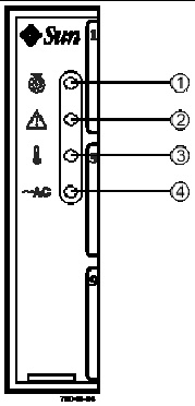
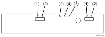
The four LEDs on the front of the Sun StorageTek 2540 Array, the Sun StorageTek 2530 Array, the Sun StorageTek 2510 Array, and the Sun StorageTek 2501 Expansion tray are identical in appearance and function. The LEDs are located on the left-side endcap of the tray.
FIGURE 1-3 Location of the LEDs on the Front of the Trays
This section reviews the components that can be accessed from the back of a:
Sun StorageTek 2500 Series Array
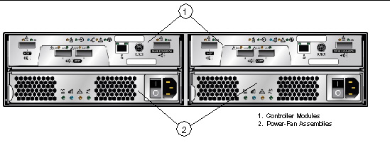
Components that are accessed from the rear of the Sun StorageTek 2500 Series Array controller trays include:
FIGURE 1-4 Controller Tray Rear-Access Components
Sun StorageTek 2501 Drive Expansion Tray
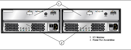
Components that are accessed from the rear of the Sun StorageTek 2501 Drive Expansion Tray are:
FIGURE 1-5 Drive Expansion Tray Rear-Access Components
The Sun StorageTek 2540, 2530, and 2510 Arrays usually have two controllers (single-controller configurations are available, but are not recommended). The controllers manage the input/output (I/O) between the volumes and the data host. The controllers have an Ethernet connection to the management host for out-of-band management and contain a battery that provides backup power to the cache memory for up to three days in the event of a power loss.
Because each controller tray contains two controllers, the data path through one controller can fail and the other controller provides a redundant data path to all of the disk drives. If a controller fails, you can replace the failed controller while the power is applied and the storage array is processing data (a hot swap).
Each controller has a media access control (MAC) address that identifies it on the network. The MAC address for a controller is on a label on the controller. The MAC address label is attached to the controller at the rear of the tray near the serial port.
The tray ID numbers are set by the trays themselves on first power on. However, you can change the setting through the Common Array Manager software. The tray ID numbers on both of the controllers in one controller tray are identical under optimal operating conditions.
This Fibre Channel (FC) controller tray provides the following capabilities:
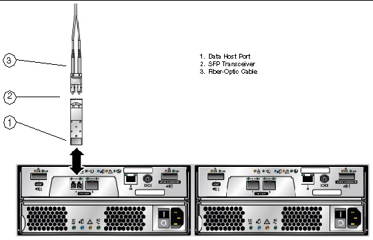
When fiber-optic cables are used to connect to the data host, a Small Form-factor Pluggable (SFP) transceiver is required to make the connection.
FIGURE 1-6 Sun StorageTek 2540 Array Ports
You can connect the Sun StorageTek 2540 Array to either copper host interface cables or fiber optic host interface cables. If you use fiber-optic cables, you must install an SFP transceiver in each interface port on the controller where a fiber-optic cable is to be installed. The SFP transceiver is required to translate the optical signals from the fiber-optic cable into digital signals for the controller.
| Note - The SFP transceiver shown might look different from those that are shipped with your controller tray. The difference does not affect transceiver performance. |
FIGURE 1-7 SFP Transceiver for the Sun StorageTek 2540 Array
This SAS controller tray provides the following capabilities:
FIGURE 1-8 Sun StorageTek 2530 Array Controller Ports
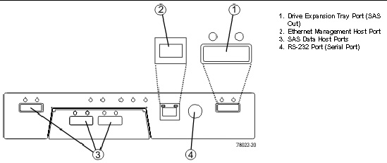
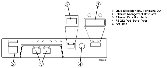
This iSCSI controller tray provides the following capabilities:
FIGURE 1-9 Sun StorageTek 2510 Array Ports
The power-fan assembly for the Sun StorageTek 2540 Array, the Sun StorageTek 2530 Array, and the Sun StorageTek 2510 Array is identical and interchangeable.
| Note - A minimum of two disk drives must be operating in a controller tray or in a drive expansion tray to avoid generating a power-fan assembly error. |
The power-fan assembly contains an integrated cooling fan. The power supply provides power to the internal components by converting incoming AC voltage to DC voltage. The fan circulates air inside of the tray by pulling air in through the vents on the front of the assembly and pushing the air out of the vents on the back of each fan.
Each tray contains two power-fan assemblies. If one power supply is turned off or malfunctions, the other power supply maintains electrical power to the tray. Likewise, the fans provide redundant cooling. If one of the fans in either fan housing fails, the remaining fan continues to provide sufficient cooling to operate the tray. The remaining fan runs at a higher speed until the failed fan is replaced. Replace the failed fan as soon as possible.
The drive expansion tray expands the storage capacity of a storage array. The controllers in the controller tray can connect to the drive expansion tray and access the disk drives in the drive expansion tray for additional storage. A drive expansion tray contains both physical components (disk drives, Input/Output Modules (IOMs), and power-fan assemblies) and logical components (virtual disks and volumes).
The expansion tray contains two IOMs that provide the interface between the disk drives in the expansion tray and the controllers in the controller tray. Each controller in the controller tray connects to an IOM.
If one IOM fails, the other IOM provides a redundant data path to the disk drives. You can replace a failed IOM while the power to the storage array is turned on and the storage array is processing data (a hot swap).
The IOM uses SAS cables to enable the controller tray to communicate with the disk drives in the drive expansion trays. Each IOM in a drive expansion tray has two SAS expansion ports. One port shows an up arrow, and the other port shows a down arrow.
FIGURE 1-10 SAS Ports on the Expansion Tray IOM

When connecting the SAS cable from an IOM in one drive expansion tray to an IOM in another drive expansion tray, connect from a port with a down arrow to a port with an up arrow.
| Note - If the cable is plugged into two ports with arrows of the same direction, communication between the two drive expansion trays is lost. |
FIGURE 1-11 Locations of the Controller LEDs on the Sun StorageTek 2540 and 2510 Arrays
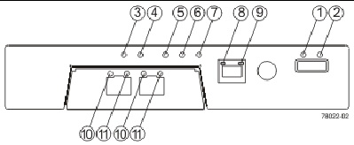
1 |
At least one link has an error, or an incompatible connection has been made.[1] |
|||
2 |
||||
3 |
||||
4 |
Indicates that all data has been written to the disk and the cache is empty. |
|||
5 |
||||
6 |
||||
7 |
||||
8 |
||||
9 |
||||
10 and 11 |
Both LEDs on indicate a 4-Gb/s data rate from the management software host. Left LED on and right LED off indicate a 1-Gb/s data rate from the management software host. Right LED on and left LED off indicate a 2-Gb/s data rate from the management software host. |
Both LEDs off indicate no link to the management software host. |
||
10 |
||||
11 |
FIGURE 1-12 Locations of the Controller LEDs on the Sun StorageTek 2530 Array
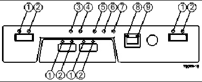
1 |
At least one link has an error, or an incompatible connection has been made.[2] |
|||
2 |
||||
3 |
||||
4 |
Indicates that all data has been written to the disk and the cache is empty. |
|||
5 |
||||
6 |
||||
7 |
||||
8 |
||||
9 |
The power-fan assembly LEDs for the Sun StorageTek 2540 Array, the Sun StorageTek 2530 Array, the Sun StorageTek 2510 Array, and the Sun StorageTek 2501 drive expansion tray are identical.
FIGURE 1-13 Locations of the Power-Fan Assembly LEDs

1 |
||||
2 |
||||
3 |
||||
4 |
FIGURE 1-14 Locations of the IOM LEDs
|
A link error occurred, or an incompatible connection has been made.[3] |
||||
Each controller, power-fan assembly, IOM, and disk drive has a Service Action Allowed LED. The Service Action Allowed LED indicates when you can remove a component safely. See LEDs on the Rear of the Trays for the locations and descriptions of the Service Action Allowed LEDs on a controller tray and a drive expansion tray, and see LEDs on the Disk Drives for disk drive Service Allowed LEDs.
If a CRU or module fails and must be replaced, the Service Action Required LED on that module turns on to indicate that a service action is required. The Service Action Allowed LED turns on if it is safe to remove the CRU or module. If there are data availability dependencies or other conditions that dictate that a CRU or module should not be removed, the Service Action Allowed LED remains off.
The Service Action Allowed LED automatically turns on or turns off as conditions change. In most cases, the Service Action Allowed LED turns on when the Service Action Required (Fault) LED is turned on for a CRU or module.
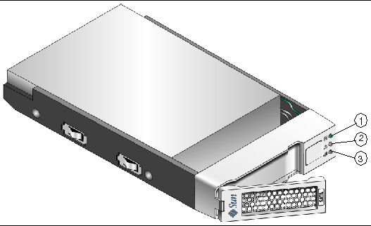
Disk drives for the Sun StorageTek 2500 Series Array have three components:
The disk drives can be Serial Advance Technology Attachment (SATA) disk drives, Fibre Channel (FC) disk drives, or SAS disk drives.
Controller trays or drive expansion trays hold up to 12 disk drives, for a maximum of 48 disk drives in a storage array. To reach the maximum of 48 disk drives, the storage array must consist of one controller tray and three drive expansion trays.
Access to disk drives is from the front of the tray.
Refer to the storage array release notes for supported drives.
Disk drives can be mixed, provided you adhere to these additional rules:

The physical locations of the disk drives are numbered 1 through 12, from left to right, and from top to bottom. The right end cap has numbers on the side showing the numbers of the adjacent drives. The Service Advisor feature of the Common Array Manager software automatically detects a disk drive’s tray ID and slot designation.
FIGURE 1-16 Locations of the Disk Drive LEDs
The Sun StorageTek 2500 Series Array is managed by the Sun StorageTek Common Array Manager software. The Common Array Manager provides web browser-based management and configuration from an external management host, data host software that controls the data path between the data host and the array, and a remote command-line interface (CLI) client that provides the same control and monitoring capability as the web browser, and is scriptable for running frequently performed tasks.
The Common Array Manager software includes Service Advisor, an online reference full of hardware and software configuration and troubleshooting information and procedures.
For information about installing the Common Array Manager software and configuring and managing the array, see the Sun StorageTek Common Array Manager Software Installation Guide.
The majority of replaceable units are designed to be replaceable by customers.
To see a list of the hardware components that can be replaced at the customer site refer to Service Advisor in the Sun StorageTek Common Array Manager software.
The Service Advisor also provides information and procedures for replacing array components.
| Note - The replaceable components inside your controller tray or drive expansion tray are referred to as either customer replaceable units (CRUs) or as modules. |
© © 2009 Sun Microsystems, Inc. All rights reserved.