Exit Print View

Sun Datacenter InfiniBand Switch 72 Topic Set

Get PDF Book Print View
 

Document Information

Using This Documentation

Related Documentation

Documentation, Support, and Training

Documentation Feedback

User Guide

Installing the Switch

Understanding Switch Specifications

Physical Specifications

Environmental Requirements

Acoustic Noise Emissions

Electrical Specifications

Network Management Connector and Pins

USB Management Connector and Pins

CXP Connector and Pins

Routing Service Cables

Power Cord Requirements

Management Cable Requirements

Understanding InfiniBand Cabling

InfiniBand Cable Cautions

InfiniBand Cable Guidelines

InfiniBand Cable Types

InfiniBand Cable Path Lengths

InfiniBand Cable Bundling

Floor and Underfloor Delivery of InfiniBand Cables

Overhead Delivery of InfiniBand Cables

Understanding the Installation

Installation Preparation

Suggested Tools

Antistatic Precautions

Installation Responsibilities

Installation Sequence

Shipping Carton Contents

Install the Switch in the Rack

Powering On the Switch

Attach the Management Cables

Attach the Power Cords

Accessing the Management Controller

Access the Management Controller From the Network Management Port

Access the Management Controller From the USB Management Port

Verify the Switch Status

Start the Subnet Manager

Connecting InfiniBand Cables

Attach the InfiniBand Cables

Check Link Status

Verifying the InfiniBand Fabric

Discover the InfiniBand Fabric Topology

Perform Diagnostics on the InfiniBand Fabric

Validate the InfiniBand Fabric and Report Errors

Administering the Switch

Servicing the Switch

Reference

Understanding the Commands

Index

CXP Connector and Pins

The CXP connector has three InfiniBand port connections.
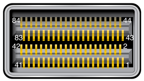
Illustration shows the pins of the CXP connector.

The following table lists the pinout for each connection.

Pin
Signal
Pin
Signal
Pin
Signal
Pin
Signal
1
GND
22
GND
43
GND
64
GND
2
TX0p
23
TX1p
44
RX3p
65
RX2p
3
TX0n
24
TX1n
45
RX3n
66
RX2n
4
GND
25
GND
46
GND
67
GND
5
TX2p
26
TX3p
47
RX1p
68
RX0p
6
TX2n
27
TX3n
48
RX1n
69
RX0n
7
GND
28
GND
49
GND
70
GND
8
TX4p
29
TX5p
50
RX7p
71
RX6p
9
TX4n
30
TX5n
51
RX7n
72
RX6n
10
GND
31
GND
52
GND
73
GND
11
TX6p
32
TX7p
53
RX5p
74
RX4p
12
TX6n
33
TX7n
54
RX5n
75
RX4n
13
GND
34
GND
55
GND
76
GND
14
TX8p
35
TX9p
56
RX11p
77
RX10p
15
TX8n
36
TX9n
57
RX11n
78
RX10n
16
GND
37
GND
58
GND
79
GND
17
TX10p
38
TX11p
59
RX9p
80
RX8p
18
TX10n
39
TX11n
60
RX9n
81
RX8n
19
GND
40
GND
61
GND
82
GND
20
SCL
41
VCC3.3-Tx
62
PRSNT
83
VCC3.3-Rx
21
SDA
42
VCC12-Tx
63
Int_L/Reset_L
84
VCC12-Rx

The following table provides descriptions of the CXP signals.

Signal
Description
GND
Ground for both signal and power return
VCC3.3-Tx
3.3V standby power from the power supplies
VCC3.3-Rx
3.3V standby power return
VCC12-Tx
12V power for cable export and future enhancements
VCC12-Rx
12V power return
TXportdiff
Differential InfiniBand transmit signal, where:
  • port0 to 11

  • diffn or p for negative or positive

RXportdiff
Differential InfiniBand receive signal, where:
  • port0 to 11

  • diffn or p for negative or positive

SCL
I2C clock
SDA
I2C data I/O
PRSNT
Connection present
Int_L/Reset_L
Reset line
Related Information