JavaScript is required to for searching.
Skip Navigation Links
Exit Print View
Sun Flash Accelerator F20 PCIe Card

User's Guide

search filter icon
search icon

Document Information

Preface

Product Notes

Related Documentation

Feedback

Access to Oracle Support

Preparing for Installation

Understanding Card Features

Flash Module Architecture Overview

Energy Storage Module Overview

Required ESM Replacement

Ship Kit Contents

Required Tools

Observing Safety Precautions

General Safety Information

Safety Symbols

ESD Safety Measures

Perform ESD Prevention Measures

Update the Host System

Installing the Card

Installing the Hardware

Verify Available PCIe Slot

(Optional) Install Full-Height Bracket

Install the Card Into a System

Card LED Locations

FMod Alignment for Optimal Performance

(Optional) Using the SAS/SATA Controller as a Boot Device

SAS/SATA Controller as a Boot Device

Configure the SAS/SATA Controller as a Boot Device (SPARC Systems)

Configure the SAS/SATA Controller as a Boot Device (x86 Systems)

Remove the Card From a System

Servicing the Card

Servicing FMods

Locate an FMod Using Software

FMod Physical Locations

Remove an FMod

Install an FMod

Replacing FMod Retention Clips

Servicing the ESM

Monitoring ESP Lifespan

Removing the ESM

Installing the ESM

Updating the FMod Firmware

Update the FMod Firmware (Oracle Solaris OS)

Update the FMod Firmware (Windows and Linux OS)

Updating the SAS/SATA Controller Firmware

Update the SAS/SATA Controller Firmware (Oracle Solaris OS)

Update the SAS/SATA Controller Firmware (Linux OS)

Update the SAS/SATA Controller Firmware (Windows)

Replace the Card

Troubleshooting the Card

Troubleshooting Chart

Card LEDs

Understanding Specifications

Physical Dimensions

Environmental Specifications

Electrical Specifications

Connector Pinouts

Glossary

Remove an FMod

  1. Perform ESD prevention measures.

    See Perform ESD Prevention Measures.

  2. Remove the card from the system.

    If you are servicing the lower FMod, you must first remove the upper FMod.

    1. Note the location of each FMod on the card.

      You must replace FMods in the same locations to retain consistent device addresses after servicing the card.

    2. Slightly loosen the retention clip screws before attempting to remove the FMod.

      Loosen the clip screws 1-2 turns to prevent breaking the clips.

    3. Gently disengage the retention levers from the FMod.
    4. Pull the FMod straight up and off the card.

      The FMod near the faceplate is held in place by a groove on the back of the faceplace. Remove this FMod at an angle to free it from the metal groove.
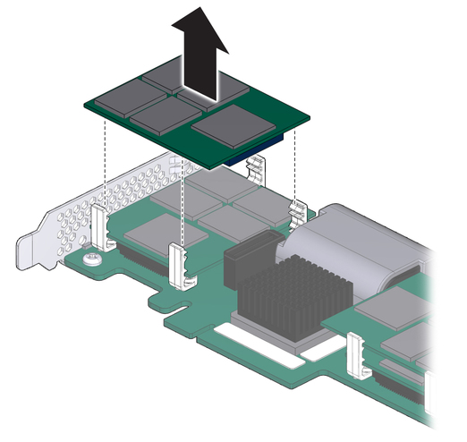

      image:Figure showing how to remove an FMod from the card.
  3. Place the FMod on an antistatic mat.
Related Information