| Skip Navigation Links | |
| Exit Print View | |

|
Sun Fire X4470 Server Service Manual |
1. Sun Fire X4470 Server Service Manual Overview
1.1.1 Intel Xeon 7500 Platform
1.1.7 Summary of Supported Components and Capabilities
1.2 Server Front Panel Features
1.3 Server Back Panel Features
1.4 Performing Service Related Tasks
2. Preparing to Service the Sun Fire X4470 Server
2.1 Location of Replaceable Components
2.2 Tools and Equipment Needed
2.3 Performing Electrostatic Discharge and Static Prevention Measures
2.3.1 Using an Antistatic Wrist Strap
2.4 Positioning the Server for Maintenance
Extend the Server to the Maintenance Position
2.5 Releasing the Cable Management Arm
Power Off the Server Using the Service Processor Command-Line Interface
2.7 Removing the Server Top Cover
2.8 Removing or Installing Filler Panels
2.9 Attaching Devices to the Server
3. Servicing CRU Components That Do Not Require Server Power Off
3.1 Servicing Disk Drives (CRU)
3.1.1 Disk Drive Status LED Reference
3.1.2 Removing and Installing Disk Drives and Disk Drive Filler Panels
Remove a Disk Drive Filler Panel
Install a Disk Drive Filler Panel
3.2 Servicing Fan Modules (CRU)
3.2.2 Fan Module LED Reference
3.2.3 Detecting Fan Module Failure
3.2.4 Removing and Installing Fan Modules
3.3 Servicing Power Supplies (CRU)
3.3.1 Power Supply LED Reference
3.3.2 Detecting a Power Supply Failure
3.3.3 Removing and Installing Power Supplies
4. Servicing CRU Components That Require Server Power Off
4.1 Servicing Memory Risers and DIMMs (CRU)
4.1.1 CPUs, Memory Risers, and DIMMs Physical Layout
4.1.2 Memory Riser Population Rules
4.1.3 Memory Riser DIMM Population Rules
4.1.4 Memory Performance Guidelines
4.1.4.1 Recommended Memory Placement
4.1.7 Removing and Installing Memory Risers, DIMMs, and Filler Panels
Remove a Memory Riser Filler Panel
Remove a Memory Riser and DIMM
Install Memory Risers and DIMMs
4.2 Servicing PCIe Cards (CRU)
4.2.1 PCIe Card Configuration Rules
4.2.2 PCIe Cards With Bootable Devices
4.2.3 Avoiding PCI Resource Exhaustion Errors
4.2.4 Removing and Installing PCIe Cards and PCIe Card Filler Panels
Remove a PCIe Card Filler Panel
Install a PCIe Card Filler Panel
4.3 Servicing the DVD Drive and DVD Driver Filler Panel (CRU)
Remove the DVD Drive or DVD Drive Filler Panel
Install the DVD Drive or DVD Drive Filler Panel
4.4 Servicing the System Lithium Battery (CRU)
5.1 Servicing the CPU and Heatsink (FRU)
5.1.2 Removing and Installing a Heatsink Filler Panel, CPU Cover Plate, Heatsink, and CPU
5.2 Servicing the Fan Board (FRU)
5.3 Servicing the Power Supply Backplane (FRU)
Remove the Power Supply Backplane
Install the Power Supply Backplane
5.4 Servicing the Disk Drive Backplane (FRU)
Remove the Disk Drive Backplane
Install the Disk Drive Backplane
5.5 Servicing the Motherboard (FRU)
6. Returning the Server to Operation
6.1 Replacing the Server Top Cover
6.2 Returning the Server to the Normal Rack Position
Return the Server to the Normal Rack Position
7. Servicing the Server at Boot Time
7.3 Default BIOS Power-On Self-Test (POST) Events
7.4 BIOS POST F1 and F2 Errors
7.5 How BIOS POST Memory Testing Works
7.6 Ethernet Port Device and Driver Naming
7.6.1 Ethernet Port Booting Priority
7.8 Performing Common BIOS Procedures
7.8.1 Configuring Serial Port Sharing
8. Troubleshooting the Server and Oracle ILOM Defaults
8.1 Troubleshooting the Server
8.2.1 Diagnostic Tool Documentation
8.3 Using the Preboot Menu Utility
8.3.1 Accessing the Preboot Menu
8.3.2 Restoring Oracle ILOM to Default Settings
8.3.3 Restoring Oracle ILOM Access to the Serial Console
8.3.4 Restoring the SP Firmware Image
8.3.5 Preboot Menu Command Summary
8.5 Locating the Chassis Serial Number
A.3 Environmental Requirements
B.2 BIOS Advanced Menu Selections
B.3 BIOS PCIPnP Menu Selections
B.5 BIOS Security Menu Selections
B.6 BIOS I/O MMIO Menu Selections
B.7 BIOS Chipset Menu Selections
C.3 Gigabit-Ethernet Connectors
C.4 Network Management Port Connector
 | Caution - These procedures require that you handle components that are sensitive to static discharge. This sensitivity can cause the component to fail. To avoid damage, ensure that you follow antistatic practices as described in 2.3 Performing Electrostatic Discharge and Static Prevention Measures. |
When replacing or upgrading a DIMM on the server you should consider the following:
Physical layout of the CPUs, memory risers, and DIMMs
Memory riser population rules
Memory riser DIMM population rules
Instructions for installing a DIMM
DIMM rank classifications labels
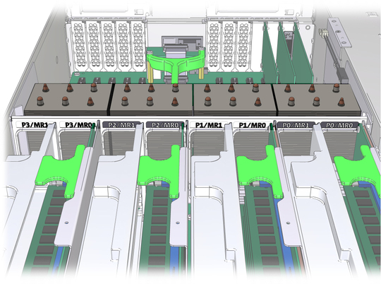
The physical layout of the CPUs, memory risers, and DIMMs is shown in CPU and Memory Riser Layout and Memory Riser DIMMs Physical Layout and Population Order.
Figure 4-1 CPU and Memory Riser Layout
Note - The system firmware checks if the installed CPUs are for the Sun Fire X4470 Server or Sun Fire X4470 M2 Server. The system firmware raises a fault for memory risers whose model belongs with the other family of CPUs.
The memory riser population rules for the Sun Fire X4470 Server are as follows:
A maximum of two memory risers (numbered MR0 and MR1) are supported per CPU, thus allowing up to eight memory risers in a 4-CPU system, or up to four memory risers in a 2-CPU system.
Each memory riser slot in the server chassis must be filled with either a memory riser or filler panel, and each memory riser must be filled with DIMMs and/or DIMM filler panels. For example, in 2-CPU systems, empty CPU sockets (P1 and P3) must have associated memory riser slots populated with two riser filler panels per CPU.
Performance-oriented configurations should be configured with two memory risers per CPU. In configurations that do not require two memory risers per CPU, the following guidelines should be followed:
First, populate riser slot MR0 for each CPU, starting with the lowest numbered CPU (P0).
Then, populate riser slot MR1 for each CPU, starting with the lowest numbered CPU (P0).
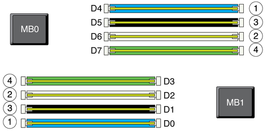
Figure 4-2 Memory Riser DIMMs Physical Layout and Population Order
The memory riser DIMM population rules for the Sun Fire X4470 Server are as follows:
On each memory riser, every DIMM slot must be filled with a DIMM or a DIMM filler panel.
Each CPU can support a maximum of 16 DIMMs (8 DIMMs per riser).
DIMMs must be installed in matched pairs of identical DIMMs (Memory Riser DIMMs Physical Layout and Population Order). Memory slot colors correspond to matched DIMM pairs. DIMMs populated in same-colored slots must have the same vendor part number.
Within a single DRAM channel, DIMMs must first be populated in the slots that are farthest from the memory buffer. For example, populate D0/D4 before D1/D5, and D2/D6 before D3/D7.
The recommended DIMM population order, as depicted in Memory Riser DIMMs Physical Layout and Population Order is:
D0/D4 (blue slots)
D2/D6 (white slots)
D1/D5 (black slots)
D3/D7 (green slots)
For best system performance, follow these guidelines, which are listed in decreasing order of importance.
Provide some DIMMs on every memory riser.
Provide DIMMs on every DRAM channel (at least 4 DIMMs per memory riser).
For each CPU, have equal total gigabytes on the MR0 and MR1 risers. Memory bandwidth is five percent higher when all pairs of risers have balanced capacity.
Spread the memory capacity evenly across the CPUs so the operating system can distribute large memory tasks better.
For the Sun Fire X4470 Server, the operating speed of the DIMMs does not decrease as more DIMMs are installed. For best memory performance, follow these guidelines to replace or add DIMMs in the server. Use one or more sizes of DIMMs, with an even number of DIMMs of each size.
Using the largest-capacity DIMMs, add two DIMMs per riser, starting at P0/MR0, continuing through P3/MR1, and then beginning again at P0/MR0 if necessary, until all of the largest-capacity DIMMs are placed.
For installations with one DIMM size, all DIMMs will be placed in this step. For installations with additional DIMMs of different sizes, continue to the next guideline step.
Using DIMMs of the next largest capacity, add two DIMMs per riser, starting with risers with the fewest DIMMs and proceeding from P0/MR0, continuing through P3/MR1, and then beginning again at P0/MR0 if necessary, until there are no more DIMMs of this size, or all risers have four DIMMs.
As long as any riser has fewer than four DIMMs, keep repeating this step with the DIMMs of decreasing capacity. When all risers have four DIMMs, continue to the next guideline step.
Using DIMMs of the next largest capacity, add two DIMMs per riser to risers with the least total GB. Start from P0/MR0, continue through P3/MR1, and then begin again at P0/MR0 if necessary.
Repeat guideline step 3 with all remaining DIMMs, in decreasing order of DIMM capacity, until all DIMMs are placed.
The eight DIMMs supported on each memory riser card in the Sun Fire X4470 Server are divided into two logical DDR3 channels. The first logical channel contains DIMMs installed in slots D0, D1, D4 and D5. The second logical channel contains DIMMs installed in slots D2, D4, D6 and D7.When one or more DIMMs within a logical DDR3 channel are faulted, all four DIMMs within that logical channel will be disabled by BIOS on subsequent boots. This isolates the faulty component from the system to ensure that proper operation is not compromised by the presence of the faulty component.
Supported DIMM Size and Organization identifies the supported DIMM sizes.
Note - Single-rank and quad-rank DIMMs are not currently offered with the Sun Fire X4470 Server.
Table 4-1 Supported DIMM Size and Organization
|
Use the following procedures to remove and install memory risers, DIMMs, and filler panels.
See 2.3 Performing Electrostatic Discharge and Static Prevention Measures.
 | Dikkat - Whenever you remove a memory riser filler panel, replace it with another filler panel or a memory riser; otherwise, the server might overheat due to improper airflow. |
See 2.3 Performing Electrostatic Discharge and Static Prevention Measures.
The filler panel is partially ejected from the socket.
 | Dikkat - Whenever you remove a DIMM filler panel, replace it with another filler panel or a DIMM; otherwise, the server might overheat due to improper airflow. |
See 2.3 Performing Electrostatic Discharge and Static Prevention Measures.
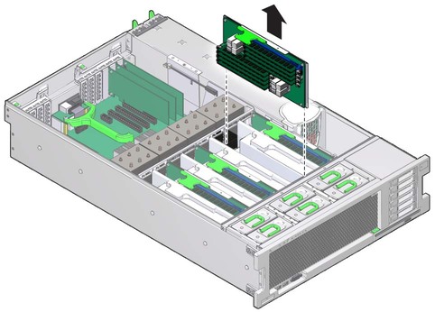
Figure 4-4 Removing the Memory Riser
The DIMM is partially ejected from the socket.
Figure 4-6 DIMM Socket Release and Alignment
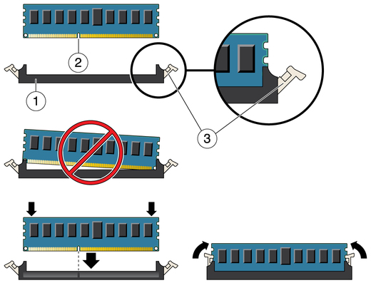
Figure Legend
1 DIMM connector slot
2 DIMM connector key
3 DIMM ejector lever
 | Dikkat - Whenever you remove a memory riser or DIMM, you should replace it with another memory riser or a DIMM or a filler panel; otherwise, the server might overheat due to improper airflow. |
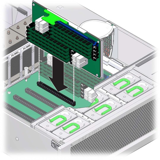
Refer to Installing DIMMs and Installing a Memory Riser Module when completing the following procedure.
Align the notch in the DIMM with the key in the connector. The notch ensures that the DIMM is oriented correctly.
Figure 4-7 Installing DIMMs
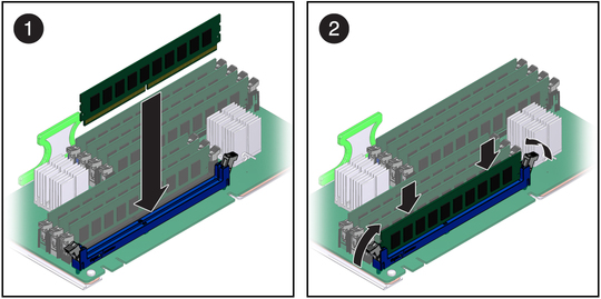
If the DIMM does not easily seat into the connector, verify that the notch in the DIMM is aligned with the key in the connector as shown in Installing DIMMs. If the notch is not aligned, damage to the DIMM might occur.
Figure 4-8 Installing a Memory Riser Module
