| Skip Navigation Links | |
| Exit Print View | |

|
Sun Fire X4470 Server Service Manual |
1. Sun Fire X4470 Server Service Manual Overview
1.1.1 Intel Xeon 7500 Platform
1.1.7 Summary of Supported Components and Capabilities
1.2 Server Front Panel Features
1.3 Server Back Panel Features
1.4 Performing Service Related Tasks
2. Preparing to Service the Sun Fire X4470 Server
2.1 Location of Replaceable Components
2.2 Tools and Equipment Needed
2.3 Performing Electrostatic Discharge and Static Prevention Measures
2.3.1 Using an Antistatic Wrist Strap
2.4 Positioning the Server for Maintenance
Extend the Server to the Maintenance Position
2.5 Releasing the Cable Management Arm
Power Off the Server Using the Service Processor Command-Line Interface
2.7 Removing the Server Top Cover
2.8 Removing or Installing Filler Panels
2.9 Attaching Devices to the Server
3. Servicing CRU Components That Do Not Require Server Power Off
3.1 Servicing Disk Drives (CRU)
3.1.1 Disk Drive Status LED Reference
3.1.2 Removing and Installing Disk Drives and Disk Drive Filler Panels
Remove a Disk Drive Filler Panel
Install a Disk Drive Filler Panel
3.2 Servicing Fan Modules (CRU)
3.2.2 Fan Module LED Reference
3.2.3 Detecting Fan Module Failure
3.2.4 Removing and Installing Fan Modules
3.3 Servicing Power Supplies (CRU)
3.3.1 Power Supply LED Reference
3.3.2 Detecting a Power Supply Failure
3.3.3 Removing and Installing Power Supplies
4. Servicing CRU Components That Require Server Power Off
4.1 Servicing Memory Risers and DIMMs (CRU)
4.1.1 CPUs, Memory Risers, and DIMMs Physical Layout
4.1.2 Memory Riser Population Rules
4.1.3 Memory Riser DIMM Population Rules
4.1.4 Memory Performance Guidelines
4.1.4.1 Recommended Memory Placement
4.1.7 Removing and Installing Memory Risers, DIMMs, and Filler Panels
Remove a Memory Riser Filler Panel
Remove a Memory Riser and DIMM
Install Memory Risers and DIMMs
Install a Memory Riser Filler Panel
4.2 Servicing PCIe Cards (CRU)
4.2.1 PCIe Card Configuration Rules
4.2.2 PCIe Cards With Bootable Devices
4.2.3 Avoiding PCI Resource Exhaustion Errors
4.2.4 Removing and Installing PCIe Cards and PCIe Card Filler Panels
4.3 Servicing the DVD Drive and DVD Driver Filler Panel (CRU)
Remove the DVD Drive or DVD Drive Filler Panel
Install the DVD Drive or DVD Drive Filler Panel
4.4 Servicing the System Lithium Battery (CRU)
5.1 Servicing the CPU and Heatsink (FRU)
5.1.2 Removing and Installing a Heatsink Filler Panel, CPU Cover Plate, Heatsink, and CPU
5.2 Servicing the Fan Board (FRU)
5.3 Servicing the Power Supply Backplane (FRU)
Remove the Power Supply Backplane
Install the Power Supply Backplane
5.4 Servicing the Disk Drive Backplane (FRU)
Remove the Disk Drive Backplane
Install the Disk Drive Backplane
5.5 Servicing the Motherboard (FRU)
6. Returning the Server to Operation
6.1 Replacing the Server Top Cover
6.2 Returning the Server to the Normal Rack Position
Return the Server to the Normal Rack Position
7. Servicing the Server at Boot Time
7.3 Default BIOS Power-On Self-Test (POST) Events
7.4 BIOS POST F1 and F2 Errors
7.5 How BIOS POST Memory Testing Works
7.6 Ethernet Port Device and Driver Naming
7.6.1 Ethernet Port Booting Priority
7.8 Performing Common BIOS Procedures
7.8.1 Configuring Serial Port Sharing
8. Troubleshooting the Server and Oracle ILOM Defaults
8.1 Troubleshooting the Server
8.2.1 Diagnostic Tool Documentation
8.3 Using the Preboot Menu Utility
8.3.1 Accessing the Preboot Menu
8.3.2 Restoring Oracle ILOM to Default Settings
8.3.3 Restoring Oracle ILOM Access to the Serial Console
8.3.4 Restoring the SP Firmware Image
8.3.5 Preboot Menu Command Summary
8.5 Locating the Chassis Serial Number
A.3 Environmental Requirements
B.2 BIOS Advanced Menu Selections
B.3 BIOS PCIPnP Menu Selections
B.5 BIOS Security Menu Selections
B.6 BIOS I/O MMIO Menu Selections
B.7 BIOS Chipset Menu Selections
C.3 Gigabit-Ethernet Connectors
C.4 Network Management Port Connector
This section describes how to remove and install PCIe cards.
For the location of the PCIe slots, see 1.3 Server Back Panel Features.
The server supports up to ten low-profile PCIe 2.0 cards. Refer to the Sun Fire X4470 Server Product Notes (821-0704) for details about supported PCIe cards, along with card quantity and slot restrictions.
The following PCIe card slots are available on the server:
Slots 0 and 9: x4 electrical interface
Slots 1, 2, 4, 6, 7, and 8: x8 electrical interface
Slots 3 and 5: x8 or x16 electrical interface (x16 connector)
Note - Slots 3 and 5 operate as x16 interfaces only when an x16 capable card is installed and the adjacent slot (4 or 6) is unpopulated.
To determine the slot in which to install a PCIe card, follow these guidelines:
First consider any cooling considerations that require a card to be installed in a certain slot. For information about cooling considerations for PCIe cards, refer to the Sun Fire X4470 Server Product Notes (821-0704).
If your configuration includes an internal SAS/SATA Host Bus Adapter (HBA), check to see if it has an integrated battery pack. Install a battery-backed internal HBA in slot 4, for best cooling; otherwise, put the simpler, battery-less SAS/SATA HBA in slot 2. Slot 2 is convenient for cabling, and using Slots 3 or 4 limits the availability of x16 electrical interfaces.
For high bandwidth cards, install the cards so that the load on the server is balanced between the server’s two I/O hubs (IOH), each of which connects to five of the available PCIe slots. (IOH0 connects to slots 0–4 and IOH1 to slots 5–9). Avoid slots 9 and 0 for high-bandwidth cards since those are the x4 slots. Balance the load as follows:
IOH0 (which connects to slots 0–4), might already be using some bandwidth for the ICH10 southbridge devices, so install the first high-bandwidth card in one of slots 5–8.
Install the next high-bandwidth card in one of slots 1–4. (If an internal HBA is already installed in slot 0–4, skip this step and install the next card in another of slots 5–8.)
Continue to alternate the high-bandwidth cards between slots 1–4 and 5–8.
Install lower-speed cards (for example, 1-Gbit/s Ethernet and 8-Gbit/s Fibre Channel adapters) in any remaining slots, since these cards perform well in any location, including the x4 slots, 0 and 9.
If the server has several PCIe cards installed that provide bootable devices, disable the Option ROM on the PCIe slots not used for booting so that resources are available for the slots used for booting. By default, the BIOS enables Option ROMs for PCIe slots 2 and 4, and the four Gigabit Ethernet ports. Refer to Configure Option ROM Settings for information about disabling Option ROM.
With serveral Sun x4 PCI Express Quad Gigabit Ethernet Low Profile Adapter PCIe cards (4446A-Z-N or X4446A-Z-N) installed in server slots 0 through 4, or even one of these cards installed in slots 5 through 9, BIOS might log a "PCI resource exhaustion" event. This error occurs because BIOS allocates 8 Kbytes of I/O space for each of the Quad Gigabit Ethernet cards (and only 4 Kbytes of I/O space for a typical card).
The following is a common form of the error that might be logged:
6491 Tue Dec 7 14:19:57 2010 IPMI Log minor ID = a5a9 : 12/07/2010 : 14:19:57 : System Firmware Error : sensor number = 0x00 : PCI resource exhaustion: Bus 147 Device 0 Func 0 6490 Tue Dec 7 14:19:57 2010 IPMI Log minor ID = a5a8 : 12/07/2010 : 14:19:57 : System Firmware Error : sensor number = 0x00 : PCI resource exhaustion: Bus 147 Device 0 Func 1
To eliminate the "PCI resource exhaustion" event, change the BIOS settings to disable I/O allocation for any slot where the Quad Gigabit Ethernet card is installed. Refer to 7.8 Performing Common BIOS Procedures for instructions on how to access the BIOS Setup Utility in order to disable I/O allocation from the PCIPnP menu. The exception to this workaround is that if PXE network booting will use a Quad Gigabit Ethernet card, you should leave I/O allocation enabled for that slot.Since BIOS does not allocate I/O space for empty slots, maximizing the number of empty PCIe slots in the server might also help to avoid the "PCI resource exhaustion" event.
Use the following procedures to remove and install PCIe cards and PCIe card filler panels.
 | Caution - This procedure requires that you handle components that are sensitive to static discharge. This sensitivity can cause the component to fail. To avoid damage, ensure that you follow antistatic practices as described in 2.3 Performing Electrostatic Discharge and Static Prevention Measures. |
 | Caution - Ensure that all power is removed from the server before removing or installing expansion cards. You must disconnect the power cables before performing this procedure. |
See 2.3 Performing Electrostatic Discharge and Static Prevention Measures.
See 1.3 Server Back Panel Features for information about PCIe slots and their locations.
 | Dikkat - Whenever you remove a PCIe card filler panel, you should replace it with another filler panel or a PCIe card; otherwise, the server might overheat due to improper airflow. |
 | Caution - This procedure requires that you handle components that are sensitive to static discharge. This sensitivity can cause the component to fail. To avoid damage, ensure that you follow antistatic practices as described in 2.3 Performing Electrostatic Discharge and Static Prevention Measures. |
 | Caution - Ensure that all power is removed from the server before removing or installing expansion cards. You must disconnect the power cables before performing this procedure. |
See 2.3 Performing Electrostatic Discharge and Static Prevention Measures.
See 1.3 Server Back Panel Features for information about PCIe slots and their locations.
Note the location of all cables for reinstallation later.
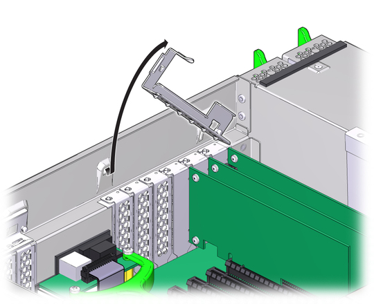
Figure 4-9 Disengaging the Crossbar

 | Dikkat - Whenever you remove a PCIe card, you should replace it with another PCIe card or a filler panel; otherwise, the server might overheat due to improper airflow. |
Refer to Installing a PCIe Card when completing the following procedure.
 | Caution - This procedure requires that you handle components that are sensitive to static discharge. This sensitivity can cause the component to fail. To avoid damage, ensure that you follow antistatic practices as described in 2.3 Performing Electrostatic Discharge and Static Prevention Measures. |
 | Caution - Ensure that all power is removed from the server before removing or installing PCIe cards. You must disconnect the power cables before performing this procedure. |
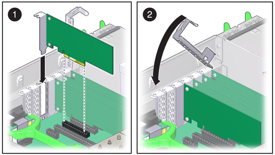
Figure 4-10 Installing a PCIe Card

For instructions on clearing server faults, refer to the Oracle Integrated Lights Out Manager (ILOM) 3.0 Supplement for Sun Fire X4470 Server (821-0702).
To create or recover RAID configurations, refer to the LSI MegaRAID SAS Software User’s Guide, which is available at the following location: http://www.lsi.com/support/sun
Refer to Installing a PCIe Card when completing the following procedure.
 | Caution - This procedure requires that you handle components that are sensitive to static discharge. This sensitivity can cause the component to fail. To avoid damage, ensure that you follow antistatic practices as described in 2.3 Performing Electrostatic Discharge and Static Prevention Measures. |
 | Caution - Ensure that all power is removed from the server before removing or installing PCIe card filler panels. You must disconnect the power cables before performing this procedure. |