| Sun Netra X4250 Server Installation Guide |
| C H A P T E R 5 |
|
Cabling the Server |
This chapter provides instructions for cabling the server. Topics include:
| Note - References to left and right are from your viewpoint as you face either the front or rear of the equipment. |
The following list describes the server’s cable connections and ports:
| Note - The serial management (SER MGT) port connection must be made using a shielded twisted-pair (STP) cable in order to comply with NEBS Lightning requirements. |
FIGURE 5-1 shows the connectors on the rear panel of the Sun Netra X4250 server.
FIGURE 5-1 Rear Panel Connectors on the Sun Netra X4250 Server

FIGURE 5-2 shows the status indicators on the front panel of the Sun Netra X4250 server.
FIGURE 5-2 Location of the Bezel Server Status and Alarm Status Indicators

To boot the server, you must connect and configure the network and serial ports. The procedures are given in the following sections.
The server also has serial and USB ports available for connections to optional devices (see Cable Connections and Ports).
| Note - When you are finished connecting the cables to the server, ensure that the server can slide smoothly in and out of the rack without binding or damaging the cables. See the section, To Verify the Operation of the Slide Rails and the CMA. |
|
The service processor serial management port is marked SER MGT (FIGURE 5-3). This port is the leftmost RJ-45 port on the rear panel.
| Note - The serial management (SER MGT) port connection must be made using a shielded twisted-pair (STP) cable in order to comply with NEBS Lightning requirements. |
| Note - The cable and DB-9 RJ-45 adapters are for the host serial port, and not for the server SER MGT port. |
Use this port for server management. This port is needed to set up the service processor network management port, as detailed in Connecting to the ILOM Service Processor for the First Time.
FIGURE 5-3 Service Processor Serial Management Port - Rear Panel

| Note - Use the service processor serial management port only for server management. This port is the default connection between the service processor and a terminal or a computer. |

|
Caution - Do not attach a modem to this port. |
 Connect a Category 5, shielded twisted-pair (STP) cable from the serial management (SER MGT) port to the terminal device.
When connecting either a DB-9 or a DB-25 cable, use an adapter to perform the crossovers given for each connector.
|
The service processor network management port is labeled NET MGT (FIGURE 5-4). This port is located just to the right of the serial management (SER MGT) port on the rear panel.
FIGURE 5-4 Service Processor Network Management Port - Rear Panel

| Note - This port is not operational until you configure the network settings (through the serial management port), as detailed in Connecting to the ILOM Service Processor for the First Time. |
| Note - If you have access to a DHCP server on the network, you can see the service processor get an IP address because the DHCP client is enabled by default. |
| Note - The service processor network management port is configured by default to retrieve network settings with Dynamic Host Configuration Protocol (DHCP) and allow connections using Solaris Secure Shell (SSH). You might need to modify these settings for your network. Instructions are given in Chapter 6. |
Connect a Category 5 cable from the NET MGT network management port to your network switch or hub.
|
The server has four network connectors, marked NET0, NET1, NET2, and NET3 (FIGURE 5-5). These connectors are RJ-45 Gigabit Ethernet.
FIGURE 5-5 Service Processor Ethernet Network Ports - Rear Panel

1. Connect a Category 5 cable from your network switch or hub to Ethernet Port 0 (NET0) on the rear of the chassis.
NET0 is the farthest left port in the 4-port network cluster in FIGURE 5-5.
2. Connect Category 5 cables from your network switch or hub to the remaining Ethernet ports (NET1, NET2, NET3), as needed.
| Note - The LEDs located above each NET port are Link/Activity (left) and Speed (right) indicators for each port. |
|
Powering on the system for the first time requires special preparation and procedures. For example, if you have not prepared a display before connecting the AC power cable, system messages could be missed.
|
|
Caution - Finish the hardware procedures in this chapter, but do not attach the AC power cable yet. |
|
|
Caution - The server goes into Standby mode and the service processor initializes as soon as the AC power cable is connected to the power source. |
Go to Powering On the System for the First Time for instructions on connecting the server to AC power.
This section provides DC power cabling and requirements information.
TABLE 5-3 lists DC power source requirements for each power supply in the Sun Netra X4250 server, and TABLE 5-4 lists DC power source requirements for the server as a whole.
| Note - DC power source must be reliably connected to ground. |
The server must meet the following requirements:
The server must meet the following requirements:
| Note - Depending on the DC power source, the -48V (negative terminal) might be marked with a minus (-) symbol, and the -48V Return (positive terminal) might be marked with a positive (+) symbol. |
When attaching DC cables, keep the following requirement in mind:
| Note - Overcurrent protection devices must meet applicable national and local electrical safety codes and be approved for the intended application. |
|
1. Identify the parts that you will use to assemble the DC input power cable (FIGURE 5-6).
The following DC connection parts are required to assemble one or more DC power input cables. These cables connect the -48V DC input sources to the power supply units.
FIGURE 5-6 DC Connection Parts

2. Turn off power from the DC power source through the circuit breakers.

|
Caution - Do not proceed with these instructions until you have turned off the power from the DC power source through the circuit breakers. |
3. Get a DC input plug from the shipping kit.
4. Locate the three wires coming from the DC power source that will be used in the connection to your unit:
| Note - Depending on the DC power source, the -48V (negative terminal) might be marked with a minus (-) symbol, and the -48V Return (positive terminal) might be marked with a positive (+) symbol. |
5. Strip 5/16 inches (8 mm) of insulation from each of the wires coming from the DC power source.
Do not strip more than 5/16 inches (8 mm) from each wire. Doing so leaves uninsulated wire exposed from the DC connector after the assembly is complete.
FIGURE 5-7 Stripping the Insulation From the Wire
.")
6. Open the cage clamp for this section of the DC input plug by taking one of the following actions:
FIGURE 5-8 Opening the Cage Clamp Using the Cage Clamp Operating Lever
FIGURE 5-9 Opening the Cage Clamp Using a Screwdriver

7. Feed the exposed section of the appropriate wire into the rectangular plug hole in the DC input plug.
FIGURE 5-10 shows which wires should be inserted into each hole in the DC input plug.
FIGURE 5-10 Assembling the DC Input Power Cable

8. Repeat Step 6 and Step 7 for the other two wires to complete the assembly of the DC input power cable.
9. Repeat Step 4 through Step 8 to create as many DC input power cables as you need for your unit.
You need two DC input power cables, one for each of the power supplies.
If you need to remove a wire from the DC input plug, insert the cage clamp operating lever or a small screwdriver into the slot directly above the wire and press down (FIGURE 5-8 and FIGURE 5-9). Pull the wire from the DC input plug.
|
1. Insert the bottom portion of the strain relief housing into the notch on the DC input plug until it snaps into place.
Ensure that the strain relief housing snaps into place on the DC input plug. You cannot complete the assembly correctly if the strain relief housing is not snapped into place.
FIGURE 5-11 Inserting the Bottom Portion of the Strain Relief Housing

2. Route the three wires coming from the DC power source through the opening at the end of the bottom portion of the strain relief housing (FIGURE 5-12).
FIGURE 5-12 Routing the Wires out of the Bottom Portion of the Strain Relief Housing

3. Insert a tie wrap into the bottom portion of the strain relief housing.
4. Loop the tie wrap over the wires and back out of the strain relief housing, and tighten the tie wrap to secure the wires to the strain relief housing (FIGURE 5-13).
FIGURE 5-13 Securing the Wires to the Strain Relief Housing

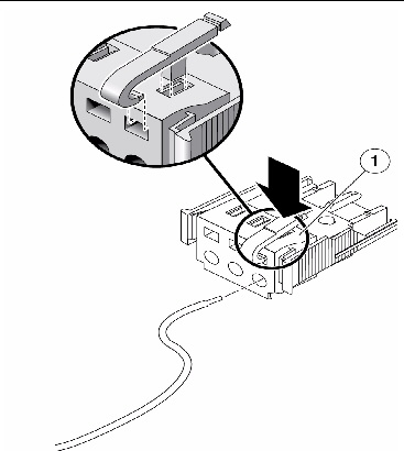
5. Lower the top portion of the strain relief housing so that the three prongs on the top portion insert into the openings in the DC input plug.
Push the top and bottom portions of the strain relief housing together until they snap into place (FIGURE 5-14).
FIGURE 5-14 Assembling the Strain Relief Housing

This section provides instruction for using the cable management assembly.
|
Once the server cables are connected and placed inside the CMA, open the velcro cable straps and wrap the straps around the CMA, securing the cables inside the CMA (FIGURE 5-15).
FIGURE 5-15 Securing the Server Cables With the CMA and Velcro Straps

| Note - Verify the operation of the slide rails and CMA, and cable service loops. Perform the steps in the following procedure again before continuing: To Verify the Operation of the Slide Rails and the CMA. |
| Sun Netra X4250 Server Installation Guide | 820-4055-11 |
Copyright © 2010, Oracle and/or its affiliates. All rights reserved.
 To Connect the Service Processor Serial Management Port