Configuring BIOS and POST
|
This chapter describes how to view or modify the BIOS Setup Utility screens in the Sun Netra X4250 server. The BIOS Setup utility reports system information and can be used to configure the server BIOS settings.
The Basic Input/Output System (BIOS) has a Setup utility stored in the BIOS flash memory. The configured data is provided with context-sensitive help and is stored in the system's battery-backed CMOS RAM. If the configuration stored in the CMOS RAM is invalid, the BIOS settings default to the original state specified at the factory.
B.1 Using BIOS Menu Items
You can access BIOS configuration screens from the following interfaces:
- Use a USB keyboard, mouse, and VGA monitor connected directly to the server.
- Use a terminal (or terminal emulator connected to a computer) through the serial port on the back panel of the server.
To access BIOS configuration screens and change the system’s parameters, do the following steps:
1. Enter the BIOS Setup utility by pressing the F2 key while the system is performing the power-on self-test (POST).
When BIOS is started, the main BIOS Setup menu screen is displayed.
2. Highlight the field to be modified using the arrow and Tab keys.
Use the left and right arrow keys to move sequentially back and forth through the menu screens. Fields that can be reconfigured are displayed in color. All other fields are nonconfigurable.
- Use the Up and Down keys on the keyboard, to scroll through a menu.
- Use the Tab key to move back and forth across columns.
3. Press Enter to select the field.
A dialog box shows the available options.
4. Modify the Setup field and close the screen.
5. If you need to modify other setup parameters, use the arrow and Tab keys to navigate to the desired screen and menu item, and then repeat Step 1 through Step 4.
Otherwise, go to Step 6.
6. Press and release the right arrow key until the Exit menu screen appears.
7. Follow the instructions on the Exit menu screen to save your changes and exit the Setup utility.
B.2 BIOS Considerations
This section contains information and considerations regarding the system BIOS.
B.2.1 Peripheral Component Interconnect (PCI) Card Slot Booting Priority
For the locations of the Sun Netra X4250 server PCI slots, see Replacing PCI-X and PCIe Cards.
The slots for the PCI cards are detected by the BIOS during startup in the following order:
1. PCIe Slot 1
2. PCIe Slot 2
3. PCI-X Slot 3
4. PCI-X Slot 4
5. PCIe Slot 5
B.2.2 Ethernet Port (NIC) Device and Driver Naming
These servers each have four 10/100/1000BASE-T Gigabit Ethernet ports (NICs). The chassis labeling of the physical ports is shown in FIGURE B-1.
FIGURE B-1 Ethernet Ports

| Note - The device naming for the NICs is reported differently by different interfaces and operating systems.
|
B.2.3 NIC Naming
TABLE B-1 illustrates the default naming used by the various operating systems for the four NICs shown in FIGURE B-1.
TABLE B-1 Sun Netra X4250 NIC Naming
|
|
Net 0
|
Net 1
|
Net 2
|
Net3
|
|
BIOS
|
slot 108
|
slot 108
|
slot 108
|
slot 108
|
|
Solaris 10
|
nge0
|
nge1
|
e1000g0
|
e1000g1
|
|
Red Hat Linux
|
eth2
|
eth3
|
eth0
|
eth1
|
|
SUSE Linux
|
eth0
|
eth1
|
eth2
|
eth3
|
|
Windows 2003
|
net
|
net2
|
net3
|
net4
|
B.2.3.1 Sun Netra X4250 Server NIC Booting Priority
The order in which the BIOS detects the Ethernet ports during bootup, and the corresponding drivers that control those ports are listed below:
1. NET 0 (Intel E1000 G0)
2. NET 1 (Intel E1000 G1)
3. NET 2 (Intel E1000 G2)
4. NET 3 (Intel E1000 G3)
B.3 BIOS Setup Screens
TABLE B-2 contains summary descriptions of the top-level BIOS setup screens.
TABLE B-2 BIOS Setup Screens Summary
|
Screen
|
Description
|
Section
|
|
Main
|
General product information, including BIOS type, processor, memory, and time and date.
|
BIOS Main Menu Screens
|
|
Advanced
|
Configuration information for the CPU, memory, IDE, Super IO, trusted computing, USB, PCI, MPS, and event log.
|
BIOS Advanced Menu Screens
|
|
Boot
|
Configure the boot device priority (hard drives and the optical media drive).
|
BIOS Boot Menu Screens
|
|
Server
|
Server devices can be configured by the BIOS (if applicable).
|
BIOS Server Menu Screens
|
|
Security
|
Set or change the user and supervisor passwords.
|
BIOS Security Menu Screens
|
|
Exit
|
Save changes and exit, discard changes and exit, discard changes, or load optimal or fail-safe defaults.
|
BIOS Exit Menu Screens
|
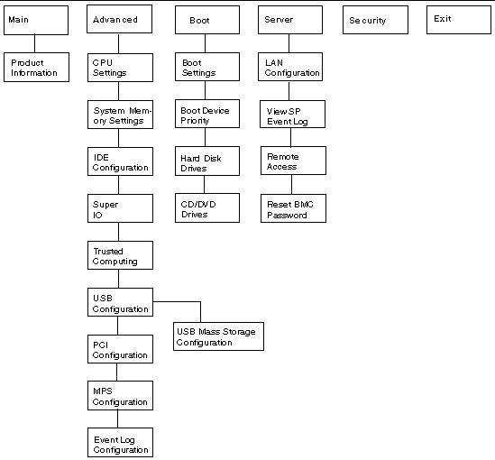
FIGURE B-2 summarizes the BIOS menu tree. See BIOS Setup Menu Screens for examples of each of these screens.
FIGURE B-2 BIOS Utility Menu Tree
 [ D ]
[ D ]
B.3.1 BIOS Setup Menu Screens
The following figures show sample Sun Netra X4250 server BIOS Setup Utility screens. All settings are set to the optimal default at startup.
| Note - The screens shown are examples. The version numbers and the screen items and selections shown are subject to change over the life of the product.
|
B.3.1.1 BIOS Main Menu Screens
The BIOS Main screens provide general product information, including BIOS type, processor type, memory, and time and date.
The Sun Netra X4250 server from Oracle has the following BIOS Main screens.
FIGURE B-3 BIOS Setup Utility: Main - System Overview

FIGURE B-4 BIOS Setup Utility: Main - Product Information

B.3.1.2 BIOS Advanced Menu Screens
The BIOS Advanced screens provide detailed configuration information for the CPU, memory, IDE, Super IO, trusted computing, USB, PCI, MPS, and other system information.
The Sun Netra X4250 server has the following BIOS Advanced screens:
FIGURE B-5 BIOS Setup Utility: Advanced

FIGURE B-6 BIOS Setup Utility: Advanced - CPU Settings

FIGURE B-7 BIOS Setup Utility: Advanced - System Memory Settings

FIGURE B-8 BIOS Setup Utility: Advanced - IDE Configuration

FIGURE B-9 BIOS Setup Utility: Advanced - Super IO Configuration

FIGURE B-10 BIOS Setup Utility: Advanced - Trusted Computing

FIGURE B-11 Bios Setup Utility: Advanced - USB Configuration

FIGURE B-12 BIOS Setup Utility: Advanced - USB Configuration 2

FIGURE B-13 BIOS Setup Utility: Advanced- PCI Configuration

FIGURE B-14 BIOS Setup Utility: Advanced- MPS Configuration

FIGURE B-15 BIOS Setup Utility: Advanced- Event Log Configuration

B.3.1.3 BIOS Boot Menu Screens
The BIOS Boot screens enable you to configure the boot device priority (hard drives and the optical media drives).
The Sun Netra X4250 server has the following BIOS Boot screens.
FIGURE B-16 BIOS Setup Utility: Boot

FIGURE B-17 BIOS Setup Utility: Boot Settings Configuration

FIGURE B-18 BIOS Setup Utility: Boot Device Priority

FIGURE B-19 BIOS Setup Utility: Boot Hard Drives

FIGURE B-20 BIOS Setup Utility: Boot CD/DVD Drives

B.3.1.4 BIOS Server Menu Screens
The BIOS Server screens enable you to configure Server devices (if applicable).
| Note - The term BMC that may be displayed on some screens refers to the SP (service processor).
|
The Sun Netra X4250 server has the following BIOS Server screens.
FIGURE B-21 BIOS Setup Utility: Server

FIGURE B-22 BIOS Setup Utility: Server - Bottom of Scroll

FIGURE B-23 BIOS Setup Utility: Server - LAN Configuration

FIGURE B-24 BIOS Setup Utility: Server - LAN Configuration - Reset SP (BMC) Password

FIGURE B-25 BIOS Setup Utility: Server - Enable Remote Access

FIGURE B-26 Bios Setup Utility: Server - View SP Event Log

FIGURE B-27 BIOS Setup Utility: Server - Clear SP Event Log

B.3.1.5 BIOS Security Menu Screens
The BIOS Security screens enable you to set or change the user and supervisor passwords.
The Sun Netra X4250 server has the following BIOS Security screens:
FIGURE B-28 BIOS Setup Utility: Security -Menu

B.3.1.6 BIOS Exit Menu Screens
The BIOS Exit screens enable you to save changes and exit, discard changes and exit, discard changes, or load optimal or fail-safe defaults.
The Sun Netra X4250 server has the following BIOS Exit screens:
FIGURE B-29 BIOS Setup Utility: Exit

FIGURE B-30 BIOS Setup Utility: Exit - Save Configuration Changes

FIGURE B-31 BIOS Setup Utility: Exit - Discard Changes

FIGURE B-32 BIOS Setup Utility: Exit - Discard Changes, Do Not Exit

FIGURE B-33 BIOS Setup Utility: Exit - Load Optimal Defaults

FIGURE B-34 BIOS Setup Utility: Exit - Load Fail-Safe Defaults

B.4 Viewing Event Logs
Use this procedure to view the BIOS event log and the SP system event log.
1. To turn on main power mode (all components powered on) if necessary, use a ball point pen or other stylus to press and release the Power button on the server front panel (FIGURE 1-6).
When main power is applied to the full server, the Power OK LED next to the Power button lights and remains lit.
2. Enter the BIOS Setup utility by pressing the F2 key while the system is performing the power-on self-test (POST).
The BIOS Main menu screen is displayed (FIGURE B-4).
3. View the BIOS event log.
a. From the BIOS Main menu screen, select Advanced.
The Advanced Settings screen is displayed (FIGURE B-5).
b. From the Advanced Settings screen, select Event Log Configuration.
The Event Logging Details screen is displayed (FIGURE B-15).
c. From the Event Logging Details screen, select View Event Log.
All unread events are displayed (FIGURE B-35).
4. View the SP system event log.
a. From the BIOS Main menu screen, select Server.
The Server screen is displayed (FIGURE B-21).
b. From the Server screen, select View SP System Event Log.
All events are displayed (FIGURE B-35).
FIGURE B-35 Event Log Screen
B.5 Setting Watchdog Timers
The watchdog timers (WDT) allow the service processor (SP) to reset or power down the system if the BIOS or operating system (OS) crashes or hangs.
Use this procedure to set the either the SP BIOS WatchDog Timer or the SP OS WatchDog Timer.
1. Enter the BIOS Setup utility by pressing the F2 key while the system is performing the power-on self-test (POST).
The BIOS Main menu screen is displayed (FIGURE B-4).
2. From the BIOS Main menu screen, select Server.
3. The Server screen is displayed (FIGURE B-21).
4. From the Server screen, select either SP BIOS WatchDog Timer Action or SP OS WatchDog Timer Action.
5. The Options screen is displayed (FIGURE B-36).
6. From the Options screen, select the desired action.
7. From the Server screen, set either the SP BIOS WatchDog Time Out or SP OS WatchDog Time Out value, if applicable.
8. Save the changes and exit BIOS Utility by pressing F10.
Alternately, you can select the Exit screen, then select Save Changes and Exit.
FIGURE B-36 SP Watch Dog Timer Options Screen

B.6 Power-On Self-Test (POST)
The system BIOS provides a rudimentary power-on self-test. The basic devices required for the server to operate are checked, memory is tested, the disk controller and attached disks are probed and enumerated, and the two Intel dual Gigabit Ethernet controllers are initialized.
The progress of the self-test is indicated by a series of POST codes. These codes are displayed at the bottom right corner of the system’s VGA screen (once the self-test has progressed far enough to initialize the system video). However, the codes are displayed as the self-test runs and scroll off of the screen too quickly to be read. An alternate method of displaying the POST codes is to redirect the output of the console to a serial port (see Redirecting Console Output).
B.6.1 How BIOS POST Memory Testing Works
The BIOS POST memory testing is performed as follows:
1. The first megabyte of DRAM is tested by the BIOS before the BIOS code is shadowed (that is, copied from ROM to DRAM).
2. Once executing out of DRAM, the BIOS performs a simple memory test (a write-read of every location with the pattern 55aa55aa).
| Note - Enabling Quick Boot causes the BIOS to skip the memory test. See Changing POST Options for more information.
|
| Note - Because the server can contain up to 64 MByte of memory, the memory test can take several minutes. You can cancel POST testing by pressing any key during POST.
|
3. The BIOS polls the memory controllers for both correctable and uncorrectable memory errors and logs those errors into the service processor.
B.6.2 Redirecting Console Output
Use the following instructions to access the service processor and redirect the console output so that the BIOS POST codes can be read.
1. Initialize the BIOS Setup utility by pressing the F2 key while the system is performing the power-on self-test (POST).
The BIOS Main menu screen is displayed.
2. Select the Advanced menu tab.
The Advanced Settings screen is displayed.
3. Select IPMI 2.0 Configuration.
The IPMI 2.0 Configuration screen is displayed.
4. Select the LAN Configuration menu item.
The LAN Configuration screen displays the service processor’s IP address.
5. To configure the service processor’s IP address (optional):
a. Select the IP Assignment option that you want to use (DHCP or Static).
- If you choose DHCP, the server’s IP address is retrieved from your network’s DHCP server and displayed using the following format:
Current IP address in BMC : xxx.xxx.xxx.xxx
- If you choose Static to assign the IP address manually, perform the following steps:
i. Type the IP address in the IP Address field.
You can also enter the subnet mask and default gateway settings in their respective fields.
ii. Select Commit and press Return to commit the changes.
iii. Select Refresh and press Return to see your new settings displayed in the Current IP address in BMC field.
6. Start a web browser and type the service processor’s IP address in the browser’s URL field.
7. When you are prompted for a user name and password, type the following:
- User Name: root
- Password: password
The Sun Integrated Lights Out Manager main GUI screen is displayed.
8. Click the Remote Control tab.
9. Click the Redirection tab.
10. Set the color depth for the redirection console at either 6 or 8 bits.
Click the Start Redirection button.
11. When you are prompted for a user name and password, type the following:
- User Name: root
- Password: password
The current POST screen is displayed.
B.6.3 Changing POST Options
These instructions are optional, but you can use them to change the operations that the server performs during POST testing. To change POST options:
1. Initialize the BIOS Setup utility by pressing the F2 key while the system is performing the power-on self-test (POST).
The BIOS Main menu screen is displayed (FIGURE B-3).
2. Select Boot.
The Boot Settings screen is displayed (FIGURE B-16).
3. Select Boot Settings Configuration.
The Boot Settings Configuration screen is displayed (FIGURE B-17).
4. On the Boot Settings Configuration screen, there are several options that you can enable or disable:
- Quick Boot - This option is disabled by default. If you enable this option, the BIOS skips certain tests while booting, such as the extensive memory test. This action decreases the time it takes for the system to boot.
- Quiet Boot - This option is disabled by default. If you enable this option, the Sun Microsystems logo is displayed instead of POST codes.
- Add On ROM Display Mode - This option is set to Force BIOS by default. This option has effect only if you have also enabled the Quiet Boot option, but this option controls whether output from the Option ROM is displayed. The two settings for this option are as follows:
Force BIOS - Remove the Sun logo and display Option ROM output.
Keep Current - Do not remove the Sun logo. The Option ROM output is not displayed.
- Boot Num-Lock - This option is on by default (keyboard Num-Lock is turned on during boot). If you set this to off, the keyboard Num-Lock is not turned on during boot.
- Wait for F1 if Error - This option is disabled by default. If you enable this option, the system will pause if an error is found during POST and will only resume when you press the F1 key.
- Interrupt 19 Capture - This option is reserved for future use. Do not change.
- Default Boot Order - The letters in the brackets represent the boot devices. To see the letters defined, position your cursor over the field and read the definition in the right side of the screen.
B.6.4 POST Codes
TABLE B-3 contains descriptions of each of the POST codes, listed in the same order in which they are generated. These POST codes appear as a four-digit string that is a combination of two-digit output from primary I/O port 80 and two-digit output from secondary I/O port 81. In the POST codes listed in TABLE B-3, the first two digits are from port 81 and the last two digits are from port 80.
TABLE B-3 POST Codes
|
Post Code
|
Description
|
|
00d0
|
Coming out of POR, PCI configuration space initialization, enabling 8111’s SMBus.
|
|
00d1
|
Keyboard controller BAT, waking up from PM, saving power-on CPUID in scratch CMOS.
|
|
00d2
|
Disabling cache, full memory sizing, and verifying that flat mode is enabled.
|
|
00d3
|
Memory detections and sizing in boot block, cache disabled, I/O APIC enabled.
|
|
01d4
|
Testing base 512KB memory. Adjusting policies and cache first 8MB.
|
|
01d5
|
Boot block code is copied from ROM to lower RAM. BIOS is now executing out of RAM.
|
|
01d6
|
Key sequence and OEM specific method is checked to determine if BIOS recovery is forced. If next code is E0, BIOS recovery is being executed. Main BIOS checksum is tested.
|
|
01d7
|
Restoring CPUID: Moving boot block-runtime interface module to RAM: determining whether to execute serial flash.
|
|
01d8
|
Decompressing runtime module into RAM. Storing CPUID information in memory.
|
|
01d9
|
Copying main BIOS into memory.
|
|
01da
|
Giving control to BIOS POST.
|
|
0004
|
Checking CMOS diagnostic byte to determine if battery power is OK and CMOS checksum is OK. If the CMOS checksum is bad, update CMOS with power-on default values.
|
|
00c2
|
Setting up boot strap processor for POST. This action includes frequency calculation, loading BSP microcode, and applying user requested value for GART Error Reporting setup question.
|
|
00c3
|
Errata workarounds applied to the BSP (No. 78 and No. 110).
|
|
00c6
|
Re-enable cache for boot strap processor, and apply workarounds in the BSP for errata No. 106, No. 107, No. 69, and No. 63 if appropriate.
|
|
00c7
|
HT sets link frequencies and widths to their final values.
|
|
000a
|
Initializing the 8042 compatible keyboard controller.
|
|
000c
|
Detecting the presence of keyboard in KBC port.
|
|
000e
|
Testing and initialization of different input devices. Traps the INT09h vector, so that the POST INT09h handler gets control for IRQ1.
|
|
8600
|
Preparing CPU for booting to OS by copying all of the context of the BSP to all application processors present. Note: APs are left in the CLI HLT state.
|
|
de00
|
Preparing CPU for booting to OS by copying all of the context of the BSP to all application processors present. Note: APs are left in the CLI HLT state.
|
|
8613
|
Initializing PM regs and PM PCI regs at early-POST. Initialize multihost bridge, if system supports it. Setup ECC options before memory clearing. Enable PCI-X clock lines in the 8131.
|
|
0024
|
Decompressing and initializing any platform specific BIOS modules.
|
|
862a
|
BBS ROM initialization.
|
|
002a
|
Generic Device Initialization Manager (DIM) - Disable all devices.
|
|
042a
|
ISA PnP devices - Disable all devices.
|
|
052a
|
PCI devices - Disable all devices.
|
|
122a
|
ISA devices - Static device initialization.
|
|
152a
|
PCI devices - Static device initialization.
|
|
252a
|
PCI devices - Output device initialization.
|
|
202c
|
Initializing different devices. Detecting and initializing the video adapter installed in the system that have optional ROMs.
|
|
002e
|
Initializing all the output devices.
|
|
0033
|
Initializing the silent boot module. Set the window for displaying text information.
|
|
0037
|
Displaying sign-on message, CPU information, setup key message, and any OEM specific information.
|
|
4538
|
PCI devices - IPL device initialization.
|
|
5538
|
PCI devices - General device initialization.
|
|
8600
|
Preparing CPU for booting to OS by copying all of the context of the BSP to all application processors present. Note: APs are left in the CLI HLT state.
|
B.6.5 POST Code Checkpoints
The POST code checkpoints are the largest set of checkpoints during the BIOS pre-boot process. TABLE B-4 describes the type of checkpoints that might occur during the POST portion of the BIOS. These two-digit checkpoints are the output from primary I/O port 80.
TABLE B-4 POST Code Checkpoints
|
Post Code
|
Description
|
|
03
|
Global initialization before the execution of actual BIOS POST. Initialize BIOS Data Area (BDA) variables to their default values. Initialize POST data variables. NMI, parity, video for EGA, and DMA controllers are disabled at this point.
|
|
04
|
Checks CMOS diagnostic byte to verify that battery power and CMOS checksum is OK. Verify CMOS checksum manually by reading storage area. If the CMOS checksum is bad, update CMOS with power-on default values and clear passwords. Initialize status register A. Initializes data variables that are based on CMOS setup questions. Initializes both the 8259 compatible PICs in the system.
|
|
05
|
Initializes the interrupt controlling hardware (generally PIC) and interrupt vector table.
|
|
06
|
Does read-write test to CH-2 count reg. Initialize CH-0 as system timer. Install the POSTINT1Ch handler. Enable IRQ-0 in PIC for system timer interrupt. Traps INT1Ch vector to POSTINT1ChHandlerBlock.
|
|
C0
|
Early CPU Init Start-Disable Cache-Init Local APIC.
|
|
C1
|
Sets up boot strap processor information.
|
|
C2
|
Sets up boot strap processor for POST. This action includes frequency calculation, loading BSP microcode, and applying user requested value for GART Error Reporting setup question.
|
|
C3
|
Errata workarounds applied to the BSP (No. 78 & No. 110).
|
|
C5
|
Enumerates and sets up application processors. This action includes microcode loading, and workarounds for errata (No. 78, No. 110, No. 106, No. 107, No. 69, No. 63).
|
|
C6
|
Re-enable cache for boot strap processor, and apply workarounds in the BSP for errata No. 106, No. 107, No. 69, and No. 63 if appropriate. In case of mixed CPU steppings, errors are sought and logged, and an appropriate frequency for all CPUs is found and applied. Note: APs are left in the CLI HLT state.
|
|
C7
|
The HT sets link frequencies and widths to their final values. This routine gets called after CPU frequency has been calculated to prevent bad programming.
|
|
0A
|
Initializes the 8042 compatible keyboard controller.
|
|
0B
|
Detects the presence of PS/2 mouse.
|
|
0C
|
Detects the presence of keyboard in KBC port.
|
|
0E
|
Testing and initialization of different input Devices. Also, update the kernel variables. Traps the INT09h vector, so that the POST INT09h handler gets control for IRQ1. Decompress all available language, BIOS logo, and silent logo modules.
|
|
13
|
Initializes PM regs and PM PCI regs at Early-POST. Initialize multihost bridge, if system supports it. Set up ECC options before memory clearing. REDIRECTION causes corrected data to written to RAM immediately. CHIPKILL provides 4 bit error det/corr of x4 type memory. Enable PCI-X clock lines in the 8131.
|
|
20
|
Relocates all the CPUs to a unique SMBASE address. The BSP will be set to have its entry point at A000:0. If fewer than 5 CPU sockets are present on a board, subsequent CPUs entry points will be separated by 8000h bytes. If more than 4 CPU sockets are present, entry points are separated by 200h bytes. CPU module will be responsible for the relocation of the CPU to correct address. Note: APs are left in the INIT state.
|
|
24
|
Decompresses and initializes any platform specific BIOS modules.
|
|
30
|
Initializes System Management Interrupt.
|
|
2A
|
Initializes different devices through DIM.
|
|
2C
|
Initializes different devices. Detects and initializes the video adapter installed in the system that have optional ROMs.
|
|
2E
|
Initializes all the output devices.
|
|
31
|
Allocates memory for ADM module and decompress it. Gives control to ADM module for initialization. Initializes language and font modules for ADM. Activate ADM module.
|
|
33
|
Initializes the silent boot module. Set the window for displaying text information.
|
|
37
|
Displaying sign-on message, CPU information, setup key message, and any OEM specific information.
|
|
38
|
Initializes different devices through DIM.
|
|
39
|
Initializes DMAC-1 and DMAC-2.
|
|
3A
|
Initializes RTC date and time.
|
|
3B
|
Tests for total memory installed in the system. Also, Check for DEL or ESC keys to limit memory test. Displays total memory in the system.
|
|
3C
|
By this point, RAM read-write test is completed, program memory holes or handle any adjustments needed in RAM size with respect to NB. Tests if HT module found an error in boot block and CPU compatibility for MP environment.
|
|
40
|
Detects different devices (Parallel ports, serial ports, and coprocessor in CPU, etc.) successfully installed in the system and update the BDA, EBDA, etc.
|
|
50
|
Programming the memory hole or any kind of implementation that needs an adjustment in system RAM size if needed.
|
|
52
|
Updates CMOS memory size from memory found in memory test. Allocates memory for Extended BIOS Data Area from base memory.
|
|
60
|
Initializes NUM-LOCK status and programs the KBD typematic rate.
|
|
75
|
Initializes Int-13 and prepares for IPL detection.
|
|
78
|
Initializes IPL devices controlled by BIOS and option ROMs.
|
|
7A
|
Initializes remaining option ROMs.
|
|
7C
|
Generates and writes contents of ESCD in NVRAM.
|
|
84
|
Logs errors encountered during POST.
|
|
85
|
Displays errors to the user and gets the user response for error.
|
|
87
|
Executes BIOS setup if needed or requested.
|
|
8C
|
After all device initialization is done, programmed any user selectable parameters relating to NB/SB, such as timing parameters, noncacheable regions, and the shadow RAM cacheability, and do any other NB/SB/PCIX/OEM specific programming needed during Late-POST. Background scrubbing for DRAM, and L1 and L2 caches are set up based on setup questions. Get the DRAM scrub limits from each node. Workaround for erratum No. 101 applied here.
|
|
8D
|
Builds ACPI tables (if ACPI is supported).
|
|
8E
|
Programs the peripheral parameters. Enable/Disable NMI as selected.
|
|
90
|
Late POST initialization of system management interrupt.
|
|
A0
|
Checks boot password if installed.
|
|
A1
|
Clean-up work needed before booting to OS.
|
|
A2
|
Takes care of runtime image preparation for different BIOS modules. Fills the free area in F000h segment with 0FFh. Initializes the Microsoft IRQ routing table. Prepares the runtime language module. Disables the system configuration display if needed.
|
|
A4
|
Initializes runtime language module.
|
|
A7
|
Displays the system configuration screen if enabled. Initializes the CPUs before boot, which includes the programming of the MTRRs.
|
|
A8
|
Prepares CPU for OS boot including final MTRR values.
|
|
A9
|
Waits for user input at config display if needed.
|
|
AA
|
Uninstalls POST INT1Ch vector and INT09h vector. Deinitializes the ADM module.
|
|
AB
|
Prepares BBS for Int 19 boot.
|
|
AC
|
Any kind of chipsets (NB/SB) specific programming needed during End- POST, just before giving control to runtime code booting to OS. Programmed the system BIOS (0F0000h shadow RAM) cacheability. Ported to handle any OEM specific programming needed during End-POST. Copies OEM specific data from POST_DSEG to RUN_CSEG.
|
|
B1
|
Saves system context for ACPI.
|
|
00
|
Prepares CPU for booting to OS by copying all of the context of the BSP to all application processors present. Note: APs are left in the CLIHLT state.
|
|
61-70
|
OEM POST error. This range is reserved for chipset vendors and system manufacturers. The error associated with this value might be different from one platform to the next.
|
| Sun Netra X4250 Server Service Manual
|
820-4056-11
|
    |
Copyright © 2010, Oracle and/or its affiliates. All rights reserved.