| Sun Netra X4250 Server Service Manual |
| C H A P T E R 5 |
|
Replacing Motherboard Assembly Components |
This chapter describes how to remove components from the motherboard assembly and how to remove the motherboard assembly itself. Topics include:
The PCI mezzanine secures the PCI cards into place with green PCI card retainers and captive (nonremovable) securing screws. FIGURE 5-1 shows the available PCI card retainers and how the retainers are used with different size PCI cards.
FIGURE 5-1 PCI Retainers and Corresponding Cards

| Note - The maximum power for PCI-X slot 4 and PCIe slot 5 PCI cards is 25 watts. Only PCI-X slot 4 and PCIe slot 5 accept full-length cards. |
1. Prepare the server for PCI card removal. See:
2. With the PCI mezzanine installed and cabled, identify which card is to be removed.
3. Loosen the appropriate PCI card retainers and securing screws (FIGURE 5-2).
The screws are captive and cannot be completely removed from the PCI mezzanine.
FIGURE 5-2 Upper PCI Card Retainers and Securing Screws

|
Retainers and securing screws are circled
|
4. Slide the card to the left and lift it out of the PCI mezzanine (FIGURE 5-3).
FIGURE 5-3 Removing PCI-X 4 and PCIe 5 Cards From the PCI Mezzanine

Set the card aside on an antistatic mat.
6. Tighten the card securing screws.
7. Perform the following tasks to bring the server back online:
1. Prepare the server for PCI card installation. See:
2. With the PCI mezzanine installed and cabled, determine which slot to install the card in and loosen the appropriate card securing screws (FIGURE 5-2).
3. Remove the replacement card from its packaging and place it onto an antistatic mat.
4. If a filler panel is installed, remove it by pulling the tab.
5. Lower the card into position on the PCI mezzanine, then slide the card to the right to seat it into the connector (FIGURE 5-4).
FIGURE 5-4 Installing PCI-X 4 and PCIe 5 Cards in the PCI Mezzanine

6. Tighten the card securing screws and appropriate PCI retainers (FIGURE 5-2).
7. Perform the following tasks to bring the server back online:
| Note - The maximum power for slot PCI-X 3 cards is 25 watts. Slot PCI-X 3 only accepts half-length PCI cards. |
1. Prepare the server for PCI card removal. See:
2. With the PCI mezzanine installed and cabled, identify which card is to be removed.
3. Loosen the appropriate PCI card retainers and securing screws (FIGURE 5-2).
The screws are captive and cannot be completely removed from the PCI mezzanine.
4. Slide the card to the left and lift it out of the PCI mezzanine (FIGURE 5-3).
FIGURE 5-5 Removing the PCI-X 3 Card From the PCI Mezzanine

Set the card aside on an antistatic mat.
6. Tighten the card securing screws.
7. Perform the following tasks to bring the server back online:
1. Prepare the server for PCI card installation. See:
2. With the PCI mezzanine installed and cabled, loosen the appropriate card securing screws (FIGURE 5-2).
3. Remove the replacement card from its packaging and place it onto an antistatic mat.
4. If a filler panel is installed, remove it by pulling the tab (FIGURE 5-6).
5. Lower the card into position on the PCI mezzanine, then slide the card to the right to seat it into the connector (FIGURE 5-6).
6. Tighten the appropriate card securing screws and PCI retainers (FIGURE 5-6).
FIGURE 5-6 Installing the PCI-X 3 Card in the PCI Mezzanine

7. Perform the following tasks to bring the server back online:
| Note - The maximum power for PCI cards in slots PCIe 1 and PCIe 2 is 25 watts. PCIe 1 and PCIe 2 slots only accept PCI cards. The SAS controller is installed in slot 0. |
1. Prepare the server for card removal. See:
2. Remove the PCI mezzanine and place it on an antistatic mat.
3. If removing the SAS controller card, disconnect the cables from the SAS controller card.
4. Loosen the appropriate card securing screws (FIGURE 5-7).
5. Lift the PCI riser assembly (with PCI card attached) from the PCI mezzanine (FIGURE 5-7).
6. If installed, remove the card securing screw on the right side of the PCI card faceplate (FIGURE 5-7).
7. Remove the PCI card from the PCI riser assembly (FIGURE 5-7).
FIGURE 5-7 Removing Lower PCIe and SAS Controller Cards

8. Set the card aside on an antistatic mat.
10. Perform the following tasks to bring the server back online:
1. Prepare the server for PCI card installation. See:
2. Remove the PCI mezzanine and place it on an anti-static mat.
3. Remove the replacement card from its packaging and place it onto an antistatic mat.
4. Loosen the appropriate PCI riser assembly securing screws (FIGURE 5-8).
5. Lift the PCI riser assembly from the PCI mezzanine and place the assembly on an antistatic mat.
6. If a filler panel is installed, remove it by pulling the tab (FIGURE 5-8).

|
Caution - Verify the PCI card you are installing matches the slot. The PCIe 0 and PCI 1 slots are different than the PCIe 2 slot (FIGURE 5-8). The SAS controller is installed in slot 0. |
7. Slide the PCI card into the PCI riser assembly connector until fully seated.
8. If the SAS controller card is being installed, connect the cables to the SAS controller card.
9. Install the card securing screw on the right side of the PCI card faceplate (FIGURE 5-8).
10. Seat the PCI riser assembly into the PCI mezzanine (FIGURE 5-8).
11. Tighten the appropriate PCI riser assembly securing screws (FIGURE 5-8).
FIGURE 5-8 Installing Lower PCIe and SAS Controller Cards

12. Perform the following tasks to bring the server back online:
1. Prepare the server for air duct removal. See:
2. Facing the server, release the tab on the right of the air duct and pull upward (FIGURE 5-9).
3. Lift the duct out of the chassis, releasing the duct from the pins on the left side of the chassis, and set it aside on an antistatic mat (FIGURE 5-9).
FIGURE 5-9 Removing the Air Duct

1. Remove the replacement air duct from its packaging.
2. With the duct at a 45 degree angle, position the pin holes in the duct to align with the pins of the chassis (FIGURE 5-10).
3. Lower the duct to the horizontal position until the tab secures in place (FIGURE 5-10).
FIGURE 5-10 Installing the Air Duct


|
Caution - This procedure requires that you handle components that are sensitive to static discharge. This sensitivity can cause the component to fail. To avoid damage, ensure that you follow antistatic practices as described in Electrostatic Discharge Safety. |
The Sun Netra X4250 server Service Required LED is lit if the system detects a FB-DIMM fault.
To use the rear panel Locator button to identify faulty FB-DIMMs:
1. Unplug all power cords from the rear panel.
2. Press the Remind button. (FIGURE 5-11)

3. Note the location of faulty FB-DIMMs.
Faulty FB-DIMMs are identified with a corresponding amber LED next to the FB-DIMM slot on the motherboard.
4. Ensure that all FB-DIMMs are seated correctly in their slots.
If re-seating the FB-DIMM does not fix the problem, remove and replace the faulty FB-DIMM.
Use the FB-DIMM guidelines, FIGURE 5-12, and TABLE 5-1 to help you plan the memory configuration of your server.
For example, a valid mixed DIMM configuration might have 4 GByte DIMMs installed in DIMM Slots A0/B0, and 2 GByte DIMMs installed in DIMM slots C0/D0.
For example, four 4 GByte DIMMs and four 2 GByte DIMMS should be installed as follows: A0/B0=4GByte DIMMs, C0/D0=4GByte DIMMs, A1/B1=2GByte DIMMs, C1/D1=2GByte DIMMs.

| Note - FB-DIMM names in ILOM messages are displayed with the full name, such as /SYS/MB/MCH/DD0. |
|
|
Caution - Ensure that all power is removed from the server before removing or installing FB-DIMMs. You must disconnect the power cables before performing this procedure. |
1. Review FB-DIMM Guidelines for memory configuration information.
2. Prepare the server for service. See:
3. If there are full-length PCBs are installed in PCIe5 and PCI-X4 slots, remove the PCI Mezzanine, if necessary.
See Removing the PCI Mezzanine.
5. If you are replacing a faulty FB-DIMM, locate the FB-DIMMs that you want to replace.
Press the Remind button on the motherboard to activate the FB-DIMM status LEDs. Any faulty FB-DIMMs will be indicated with a corresponding amber fault LED on the motherboard.
| Tip - Make a note of the faulty FB-DIMM location so that you can install the replacement FB-DIMM in the same location. |
| Note - For memory configuration information see FB-DIMM Guidelines. |
6. Push down on the ejector tabs on each side of the FB-DIMM until the FB-DIMM is released (FIGURE 5-13).
7. Grasp the top corners of the faulty FB-DIMM and remove it from the server.
.")
8. Place the FB-DIMM on an antistatic mat.
9. Repeat Step 6 through Step 8 to remove any additional FB-DIMMs.
1. Unpackage the replacement FB-DIMMs and place them on an antistatic mat.
| Tip - See FB-DIMM Guidelines for information about configuring the FB-DIMMs. |
2. Ensure that the ejector tabs are in the open position.
3. Line up the replacement FB-DIMM with the connector (FIGURE 5-14).
Align the FB-DIMM notch with the key in the connector. This action ensures that the FB-DIMM is oriented correctly.
4. Push the FB-DIMM into the connector until the ejector tabs lock the FB-DIMM in place.
If the FB-DIMM does not easily seat into the connector, verify that the orientation of the FB-DIMM is as shown in FIGURE 5-14. If the orientation is reversed, damage to the FB-DIMM might occur.
FIGURE 5-14 Installing FB-DIMMs
.")
5. Repeat Step 2 through Step 4 until all replacement FB-DIMMs are installed.
b. Perform the following tasks to bring the server back online:
Before you begin, see FB-DIMM Guidelines, for information about FB-DIMM configuration guidelines.
1. Unpackage the replacement FB-DIMMs and place them on an antistatic mat.
2. Ensure that the ejector tabs are in the open position.
3. Line up the FB-DIMM with the connector (FIGURE 5-14).
Align the FB-DIMM notch with the key in the connector. This action ensures that the FB-DIMM is oriented correctly.
4. Push the FB-DIMM into the connector until the ejector tabs lock the FB-DIMM in place.
If the FB-DIMM does not easily seat into the connector, verify that the orientation of the FB-DIMM is as shown in FIGURE 5-14. If the orientation is reversed, damage to the FB-DIMM might occur.
5. Repeat Step 2 through Step 4 until all FB-DIMMs are installed.
6. Perform the following tasks to bring the server back online:
The battery maintains system time when the server is powered off and a time server is unavailable. If the server fails to maintain the proper time when powered off and not connected to a network, replace the battery.
You need a small (No. 1 flat-blade) screwdriver.
|
|
Caution - Ensure that all power is removed from the server before removing or installing the battery. You must disconnect the power cables from the system before performing this procedure. |
1. Prepare the server for battery removal. See:
2. Pry the battery out of the service processor board using a small flat-blade screwdriver (FIGURE 5-15).
FIGURE 5-15 Prying the Battery From the Motherboard

3. Set the battery aside on an antistatic mat.
4. Continue to Installing the Battery.
| Note - The battery is a CR2032 or equivalent. |
1. Remove the replacement battery from its packaging.
2. Press the new battery in with the “+” side facing up (FIGURE 5-16).
FIGURE 5-16 Inserting the Battery Into the Service Processor Board

3. Perform the following tasks to bring the server back online:
1. Prepare the server for motherboard assembly removal. See:
2. Remove the following components:
3. Disconnect the cables connected to the motherboard (FIGURE 5-17).
a. Disconnect the cable connected to the PDB.
b. Disconnect the two cables connected to the media bay assembly.
FIGURE 5-17 Removing the Cables Connected to the Motherboard

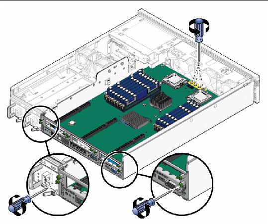
4. Loosen or remove the screws that secure the motherboard assembly to the chassis (FIGURE 5-18).
FIGURE 5-18 Removing the Motherboard Assembly Screws
5. Loosen the two captive screws at the center of the motherboard assembly (FIGURE 5-18).
6. Lift slightly and slide the motherboard assembly forward approximately one inch (25.4 mm) (FIGURE 5-19).
7. Lift up on the right edge to approximately a 45 degree angle (FIGURE 5-19).
8. Remove the motherboard assembly from the chassis (FIGURE 5-19).
FIGURE 5-19 Removing the Motherboard Assembly From the Chassis

9. Set the motherboard assembly aside on an antistatic mat.
10. Continue to Installing the Motherboard Assembly.
1. Remove the replacement motherboard assembly from its packaging and place it on an antistatic mat.
2. Lower the left edge of the motherboard assembly into the chassis, then the entire board, and while slightly elevated, slide the motherboard assembly to the back of the chassis (FIGURE 5-20).
FIGURE 5-20 Installing the Motherboard Assembly Into the Chassis

3. Align the motherboard assembly screw holes over the chassis standoffs.
4. Tighten the two captive screws at the center of the motherboard assembly (FIGURE 5-21).
FIGURE 5-21 Installing the Motherboard Assembly Screws

5. Install the two power screws and four other screws that secure the motherboard assembly to the chassis (FIGURE 5-21).
6. Reconnect the cables to the following connectors on the motherboard assembly (FIGURE 5-22):
FIGURE 5-22 Reconnecting the Cables to the Motherboard Assembly

7. Install the following components:
8. Perform the following tasks to bring the server back online:
The following topics are covered:
1. Prepare the server for service. See:
2. Identify which CPU to remove.
3. Unscrew the two heatsink screws.
4. Twist the heatsink slightly to break the seal with grease, and then lift off the heatsink.
5. Disengage the lever by pushing down and moving it to the side, and then rotating upward.
1. Prepare the server for service. See:
2. Remove the heatsink on top of the failed CPU.
4. Clean off the old thermal interface material from the heatsink and CPU, using the supplied alcohol wipe.
6. Place the new CPU in the socket.
Ensure that the orientation is correct.
Ensure that the pressure plate sits flat around the periphery of the CPU.
8. Engage the lever by rotating it downward and slipping it under the catch.
9. Using the supplied grease syringe, empty the syringe onto the CPU in a star-shaped pattern.
10. Smooth the grease into a thin, even layer on top of the CPU.
You can use a piece of plastic bag over your finger.
11. Orient the heatsink so that the two screws line up with the mounting studs.
12. Tighten the screws alternately a 1/2 turn until fully seated.
13. Return the server to operation.
14. Perform the following tasks to bring the server back online:
1. Prepare the server for service. See:
2. Remove the shipping cover from the socket.
3. Clean the top of the CPU with the provided alcohol wipe.
4. Place the CPU in the socket with the correct orientation.
Ensure that the pressure plate sits flat around the periphery of the CPU.
6. Engage the lever by rotating it downward and slipping it under the catch.
7. Remove the plastic protective cover from heatsink.
Be careful not to disturb or touch the preinstalled thermal interface material.
8. Orient the heatsink so the two screws line up with the mounting studs.
9. Tighten the screws alternately a 1/2 turn until fully seated.
10. Perform the following tasks to bring the server back online:
You can reset a password from the BIOS screen or with a jumper. You can also clear the NVRAM or BIOS password by changing the J23 jumper position as follows:
Access the J23 jumper on the motherboard in the rear, on the opposite side of the power supply unit.
2. Press F2 at the Sun splash screen to enter BIOS screen.
3. At the BIOS screen, move to the Security Screen tab.
1. Prepare the server for service. See:
Access the J23 jumper on the rear of the motherboard, on the opposite of the power supply unit.
3. Place the jumper on position 2-4.
4. Power on the server and boot until you see a message that the password has been cleared.
5. Power off the server, and remove AC power.
6. Remove the jumper from position 2-4, and replace it back to its original position.
7. Perform the following tasks to bring the server back online:
To clear the CMOS NVRAM using a jumper:
1. Prepare the server for service. See:
The jumper is on the rear of the motherboard, on the opposite side of the power supply.
3. Place the jumper on position 1-3.
4. Power on the server and boot until a message about NVRAM has been cleared.
5. Power off the server, and remove AC power.
6. Remove the jumper from position 1-3, and replace it back in its original location.
7. Perform the following tasks to bring the server back online:
| Sun Netra X4250 Server Service Manual | 820-4056-11 |
Copyright © 2010, Oracle and/or its affiliates. All rights reserved.