| C H A P T E R 3 |
|
Preparing for Service |
This chapter describes safety considerations and provides prerequisite procedures and information to replace components within the server.
This section describes important safety information you need to know prior to removing or installing parts in the server.
For your protection, observe the following safety precautions when setting up your equipment:
The following symbols might appear in this book. Note their meanings:

|
Caution - There is a risk of personal injury and equipment damage. To avoid personal injury and equipment damage, follow the instructions. |

|
Caution - Hot surface. Avoid contact. Surfaces are hot and might cause personal injury if touched. |

|
Caution - Hazardous voltages are present. To reduce the risk of electric shock and danger to personal health, follow the instructions. |
Electrostatic discharge (ESD) sensitive devices, such as the motherboard, PCI cards, hard drives, and memory cards require special handling.
Wear an antistatic wrist strap and use an antistatic mat when handling components such as drive assemblies, boards, or cards. When servicing or removing server components, attach an antistatic strap to your wrist and then to a metal area on the chassis. Then disconnect the power cords from the server. Following this practice equalizes the electrical potentials between you and the server.
Place ESD-sensitive components such as the motherboard, memory, and other PCB cards on an antistatic mat.
The server can be serviced with the following tools:
Before you can remove and install components that are inside the server, you must perform the following procedures:
Depending upon the component, you might also need to remove the PCI tray:
| Note - When replacing the hard drives or power supplies, not all of these tasks are necessary. The replacement procedures for those components address this fact. |
Performing a graceful shutdown ensure that all of your data is saved and the system is ready for restart.
1. Log in as superuser or equivalent.
Depending on the nature of the problem, you might want to view the system status, the log files, or run diagnostics before you shut down the system. See Viewing Event Logs for log file information.
Refer to your Solaris system administration documentation for additional information.
3. Save any open files and quit all running programs.
Refer to your application documentation for specific information on these processes.
4. Shut down the operating system:
If running the Solaris OS, refer to the Solaris system administration documentation for additional information.
5. Shut down the chassis power:
Refer to the Sun Integrated Lights Out Manager (ILOM) User’s Guide for more information about the stop command.
6. Disconnect the cables from the server.
See Disconnecting Cables From the Server.
Press and hold the Power button for four seconds to force main power off and to enter standby power mode. When main power is off, the Power OK LED on the front panel will begin flashing, indicating that the server is in Standby power mode.

|
Caution - The system supplies standby power to the circuit boards even when the system is powered off. |
1. Label all cables connected to the server.
2. Disconnect the following cables as appropriate:
3. If you are going to remove the CMA, also remove the cables from it.
4. Remove the server from the rack.
Remove the server from the rack prior to performing cold-swappable FRU replacement procedures except the FB-DIMMs, PCI cards, and the service processor.

|
Caution - The serverweighs approximately 40 lb (18 kg). Two people are required to dismount and carry the chassis. |
1. Disconnect all the cables and power cords from the server.
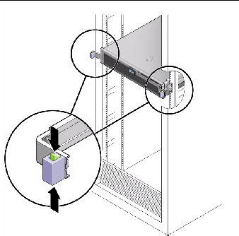
2. From the front of the server, release the slide rail latches on each side.
Pinch the green latches as shown in FIGURE 3-1.
FIGURE 3-1 Slide Release Latches
3. While pinching the release latches, slowly pull the server forward until the slide rails latch.
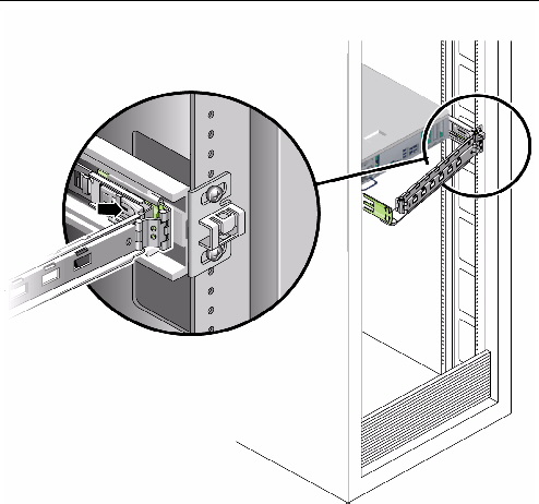
4. Press the metal lever (FIGURE 3-2) that is located on the inner side of the rail to disconnect the CMA from the rail assembly (on the right side from the rear of the rack).
The CMA is still attached to the cabinet, but the server chassis is now disconnected from the CMA.
FIGURE 3-2 Locating the Metal Lever

|
Caution - The server weighs approximately 40 lb (18 kg). The next step requires two people to dismount and carry the chassis. |
5. From the front of the server, pull the release tabs forward and pull the server forward until it is free of the rack rails.
The release tabs are located on each rail, about midway on the server.
6. Set the server on a sturdy work surface.
7. Perform antistatic measures.
See Performing Antistatic Measures.
1. Prepare an antistatic surface on which to set parts during removal and installation.
Place ESD-sensitive components such as the printed circuit boards on an antistatic mat. The following items can be used as an antistatic mat:
2. Attach an antistatic wrist strap.
When servicing or removing server components, attach an antistatic strap to your wrist and then to a metal area on the chassis. Then disconnect the power cords from the server.
All field-replaceable units (FRUs) that are not hot-swappable require the removal of the top cover.
1. Use a No. 2 Philips screwdriver to press the top cover release button (FIGURE 3-3).
FIGURE 3-3 Top Cover and Release Button
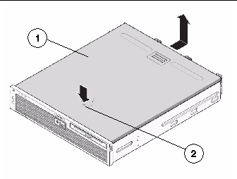
2. While pressing the top cover release button, slide the cover toward the rear of the server.
3. Lift the cover off the chassis and set the cover aside.
4. If necessary, remove the PCI mezzanine.
See Removing the PCI Mezzanine.
The PCI mezzanine is a carrier for the PCI-X and PCIe cards. Remove the PCI mezzanine to replace the following components:
It is not necessary to remove the PCI mezzanine for other components. However, when the PCI mezzanine is removed, additional working space is provided.
1. Disconnect any I/O cables from the rear of the PCI mezzanine.
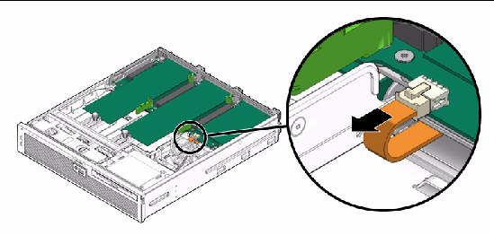
2. Disconnect the PCI mezzanine cable (FIGURE 3-5).
FIGURE 3-4 Removing the PCI Mezzanine Cable and I/O Cables From the PCI Mezzanine
3. Use a No. 2 Philips screwdriver to loosen the four green captive screws securing the PCI mezzanine (FIGURE 3-5).
4. Lift the PCI mezzanine up and out (FIGURE 3-5).
FIGURE 3-5 Removing Screws and Lifting the PCI Mezzanine
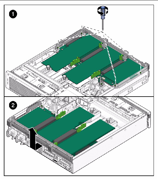
5. Lift the PCI mezzanine away from the chassis and place it on an antistatic mat.
You are now ready to replace components.
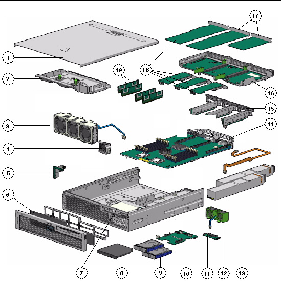
FIGURE 3-6 and TABLE 3-1 identifies the field-replaceable units (FRUs) in the server.
FIGURE 3-6 Field-Replaceable Units
|
FRU Name[1] |
||||
|---|---|---|---|---|
1 |
Requires a pen to remove. Does not power off server when removed. |
|||
2 |
||||
3 |
||||
4 |
||||
5 |
Contains the push-button circuitry and LEDs that are displayed on the bezel of the box. |
|||
6 |
||||
7 |
||||
8 |
||||
9 |
SAS, 2.5-inch 146 GB hard drives The two HDD configuration includes a removable DVD drive; the four HDD has HDD2 and HDD3 in place of the DVD. |
|||
10 |
Provides the main 12V power interconnect between the power supplies and the other boards. |
|||
11 |
Provides dry-contact switching according to alarm conditions. |
|||
12 |
Fans that provide supplemental cooling of the hard drives and optical media drive. |
|||
13 |
The 650W power supplies provide -3.3 VDC standby power at 3 @ 3 Amps and 12 VDC at 25 Amps. |
|||
14 |
Must be removed before removing the power distribution board. |
|||
15 |
||||
16 |
||||
17 |
Replacing PCI-X 4 and PCIe 5 Cards and Replacing the PCI-X 3 Card |
|||
18 |
||||
19 |
See FIGURE 5-12 and TABLE 5-1 |
Copyright © 2010, Oracle and/or its affiliates. All rights reserved.