| C H A P T E R 2 |
|
Initial Inspection of the Server |
This chapter includes the following topics:
Use the following flowchart as a sequence for using the subjects in this book to troubleshoot the server.
1 |
||
2 |
||
3 |
Perform external visual inspection and internal visual inspection. |
|
4 |
||
5 |
The first step in determining the cause of a problem with the server is to gather information from the service call paperwork or the onsite personnel. Use the following general guideline steps when you begin troubleshooting:
1. Collect information about the following items:
2. Document the server settings before you make any changes.
If possible, make one change at a time in order to isolate potential problems. In this way, you can maintain a controlled environment and reduce the scope of troubleshooting.
3. Note the results of any change that you make. Include any errors or informational messages.
4. Check for potential device conflicts before you add a new device.
5. Check for version dependencies, especially with third-party software.
Controls that have been improperly set and cables that are loose or improperly connected are common causes of problems with hardware components.
1. Check that AC or DC power cords are attached firmly to the server’s power supplies and to the AC or DC sources.
2. Check that the main cover is firmly in place.
An intrusion switch on the motherboard automatically shuts down the server power to Standby mode when the cover is removed.
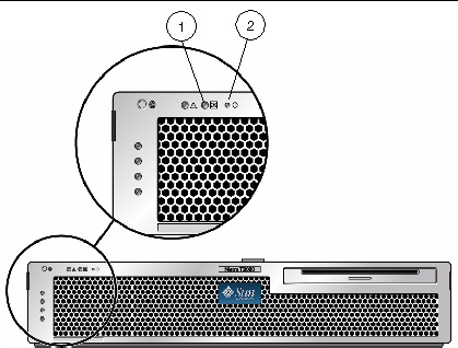
1. Inspect the external status indicator LEDs, which can indicate component malfunction.
For the LED locations and descriptions of their behavior, see Server LEDs.
2. Verify that nothing in the server environment is blocking air flow or making a contact that could short out power.
3. If the problem is not evident, continue with the next section, Internally Inspecting the Server.
1. Choose a method for shutting down the server from main power mode to Standby power mode. See FIGURE 2-1.

|
Caution - Performing an emergency shutdown can cause open files to become corrupt. Use an emergency shutdown only when necessary. |
When main power is off, the Power OK LED on the front panel will begin flashing, indicating that the server is in Standby power mode.

For instructions on removing the server cover, see Removing the Top Cover.
3. Inspect the internal status indicator LEDs. These can indicate component malfunction.
For the LED locations and descriptions of their behavior, see the service procedures for the motherboard CRUs and FRUs.
| Note - The server must be in standby power mode for viewing the internal LEDs. |
You can hold down the Locator LED button on the server back panel or front panel for 5 seconds to initiate a “push-to-test” mode that illuminates all other LEDs both inside and outside of the chassis for 15 seconds.
4. Verify that there are no loose or improperly seated components.
5. Verify that all cable connectors inside the system are firmly and correctly attached to their appropriate connectors.
6. Verify that any after-factory components are qualified and supported.
For a information supported PCI cards and DIMMs, check with your Sun customer representative..
7. Check that the installed DIMMs comply with the supported DIMM population rules and configurations, as described in FB-DIMM Guidelines.
9. To restore the server to main power mode (all components powered on), use a ballpoint pen or other stylus to press and release the Power button on the server front panel (FIGURE 2-1).
When main power is applied to the full server, the Power OK LED next to the Power button lights and remains lit.
10. If the problem with the server is not evident, you can obtain additional information by viewing the power-on self-test (POST) messages and BIOS event logs during system startup. See Viewing Event Logs.
Copyright © 2010, Oracle and/or its affiliates. All rights reserved.