| C H A P T E R 6 |
|
Replacing Chassis Components |
This chapter provides instructions for replacing chassis components. Topics include:
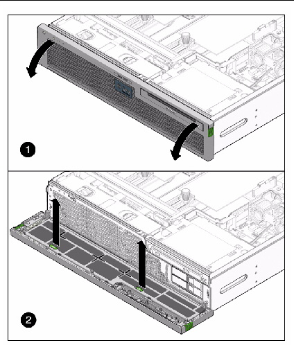
1. Press the green tabs on both sides of the bezel, and pull forward and down (FIGURE 6-1).
2. Grasp the tabs and lift the air filter from the bezel (FIGURE 6-1).
FIGURE 6-1 Opening the Bezel and Removing the Air Filter
| Note - Do not operate the server without an air filter. |
3. Continue to Installing the Air Filter.
1. Remove the replacement air filter from its packaging.
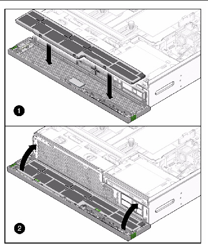
2. Insert the air filter into the bezel (FIGURE 6-2).
3. Close the bezel (FIGURE 6-2).
FIGURE 6-2 Installing the Air Filter and Closing the Bezel
The server’s redundant hot-swappable power supplies enable you to remove and replace a power supply without shutting the server down, provided that the other power supply is online and working.
The following LEDs are lit when a power supply fault is detected:
If a power supply fails and you do not have a replacement available, leave the failed power supply installed to ensure proper air flow in the server.
1. Identify which power supply requires replacement (FIGURE 6-3).
FIGURE 6-3 Locating the Power Supplies and Latches
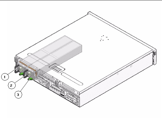
A lighted amber LED on a power supply indicates that a failure was detected. You can also use the ILOM show faulty command at the sc> prompt.
2. At the -> prompt, issue the stop /SYS/PSn command.
The stop command indicates if it is okay to perform a hot-swap of a power supply. This command does not perform any action, but it provides a warning if the power supply should not be removed because the other power supply is not providing power to the server.
In this command, PSn is the identifier for the power supply you plan to remove, either PS0 or PS1.
3. Disconnect the power cord from the faulty power supply.
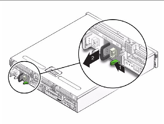
4. Grasp the power supply handle and push the power supply latch to the right (FIGURE 6-4).
5. Pull the power supply out of the chassis (FIGURE 6-4).
FIGURE 6-4 Removing a Power Supply
6. Continue to Installing a Power Supply.
1. Remove the replacement power supply from its packaging and place it on an antistatic mat.
2. Align the replacement power supply with the empty power supply bay.
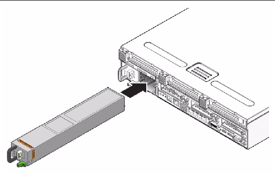
3. Slide the power supply into the bay until it is fully seated (FIGURE 6-5).
FIGURE 6-5 Installing a Power Supply
4. Reconnect the power cord to the power supply.
5. Verify that the amber LED on the replaced power supply and the service required LEDs are not lit.
6. At the -> prompt, type the show /SYS/PSn command to verify the status of the power supplies.
In this command, PSn is the identifier for the power supply you plan to remove, either PS0 or PS1.
The system fan assembly is labeled FT0.
1. Prepare the server for fan assembly removal. See:
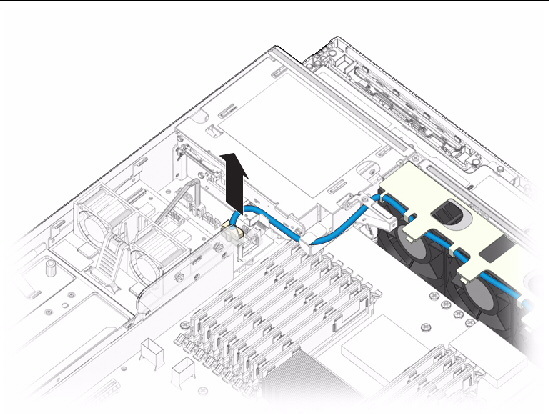
2. Disconnect the fan assembly cable from the power board (FIGURE 6-6).
FIGURE 6-6 Disconnecting the System Fan Assembly Cable
3. Remove the fan assembly cable from the cable guides.
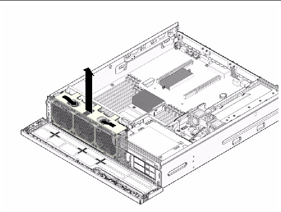
4. Insert your forefinger and thumb into the holes at the top of the fan assembly, squeeze your fingers together, and lift the fan assembly from the chassis (FIGURE 6-7).
FIGURE 6-7 Lifting the System Fan Assembly From the Chassis
5. Set the fan assembly aside on an antistatic mat.
1. Remove the replacement fan assembly from its packaging and place it on an antistatic mat.
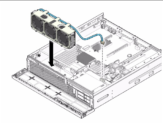
2. Insert your forefinger and thumb into the holes at the top of the fan assembly, squeeze your fingers together, and lower the fan assembly into the chassis (FIGURE 6-8).
3. Reconnect the fan assembly cable to the power board (FIGURE 6-8).
FIGURE 6-8 Installing the System Fan Assembly Into the Chassis
4. Route the fan assembly cable back into the cable guides.
The hard drive fan assembly is labeled FT1.
1. Prepare the server for hard drive fan removal. See:
2. Disconnect the hard drive fan assembly cable from the power board connector (FIGURE 6-9).
FIGURE 6-9 Disconnecting the Hard Drive Fan Assembly Cable
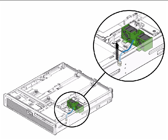
3. Carefully lift the hard drive fan assembly cable from the cable guides.
4. Push the release button on the hard drive fan bracket, and pivot the bracket backwards (FIGURE 6-10).
FIGURE 6-10 Releasing the Hard Drive Fan Bracket
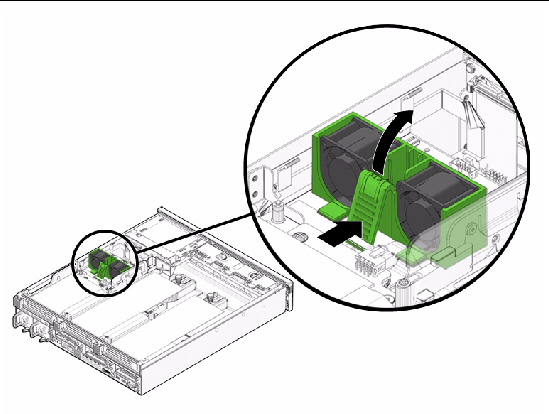
5. Slide the bracket forward and lift the hard drive fan assembly out (FIGURE 6-11).
FIGURE 6-11 Lifting Out the Hard Drive Fan Assembly
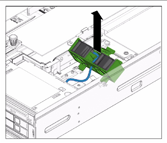
6. Set the hard drive fan assembly aside on an antistatic mat.
7. Continue to Installing the Hard Drive Fan Assembly.
1. Remove the replacement hard drive fan assembly from its packaging and place it on an antistatic mat.
2. Lower the hard drive fan assembly, and slide the hard drive fan bracket back so that the tabs enter the slots (FIGURE 6-12).
3. Pivot the hard drive fan bracket toward the rear of server until the bracket clicks.
4. Connect the hard drive fan assembly cable to the power board (FIGURE 6-12).
FIGURE 6-12 Lowering the Hard Drive Fan Assembly and Connecting the Cable
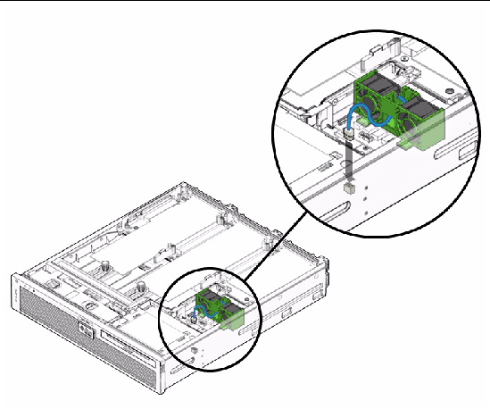
5. Route the hard drive fan assembly cable back into the cable guides.
6. Perform the following tasks to bring the server back online:
The FB-DIMM fan assembly is labeled FT2.
1. Prepare the server for FB-DIMM fan removal. See:
2. Pull the tag labeled FT2 and remove the FB-DIMM fan assembly.
3. Set the FB-DIMM fan assembly aside on an antistatic mat.
4. Continue to Installing the Hard Drive Fan Assembly.
1. Remove the replacement FB-DIMM fan assembly from its packaging and place it on an antistatic mat.
2. Reinsert the FB-DIMM fan assembly in the slot with the airflow direction arrow facing rear of server.
3. Slide the FB-DIMM fan assembly in the slot until fully seated.
4. Perform the following tasks to bring the server back online:
1. Prepare the server for alarm board removal. See:
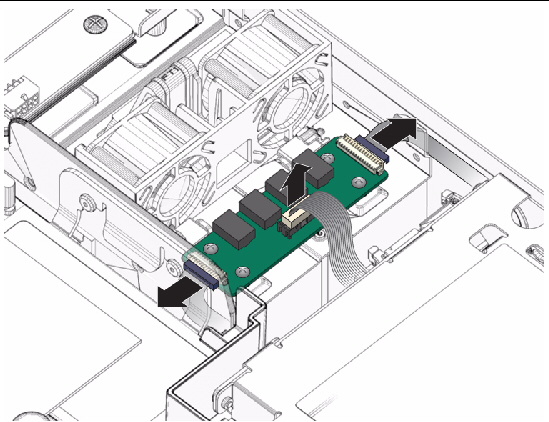
2. Disconnect the cables from the alarm board (FIGURE 6-13):
FIGURE 6-13 Disconnecting the Cables From the Alarm Board
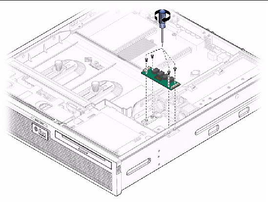
3. Remove the four alarm board screws, and lift the board up and out of the chassis (FIGURE 6-14).
FIGURE 6-14 Removing the Alarm Board Screws and Removing From the Chassis
4. Set the alarm board aside on an antistatic mat.
1. Remove the replacement alarm board from its packaging and place it on an antistatic mat.
2. Seat the alarm board back into the chassis, and tighten the four alarm board screws.
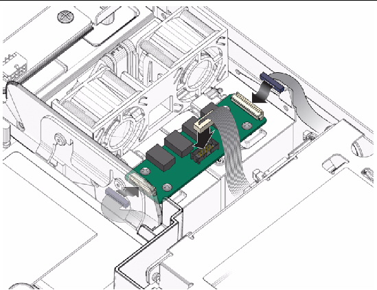
3. Reconnect the alarm board cables (FIGURE 6-15).
FIGURE 6-15 Reconnecting the Alarm Board Cables
4. Route the cables into the cable guides.
1. Prepare the server for LED board removal. See:
3. Remove the system fan assembly.
See Removing the System Fan Assembly.
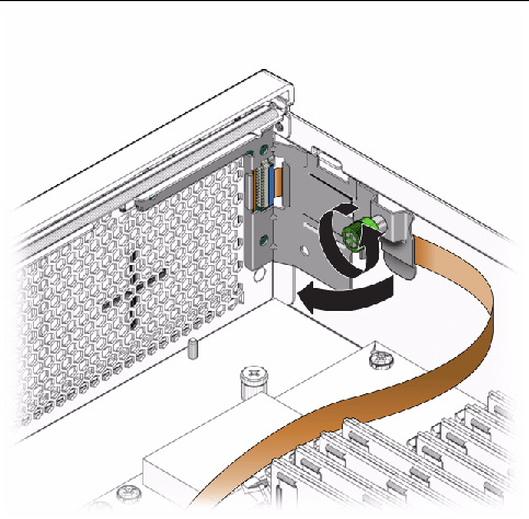
4. Loosen the thumbscrew of the LED board and swing the board out to the left (FIGURE 6-16).
FIGURE 6-16 Removing the LED Board
5. Carefully lift the LED board and cable from the cable clips.
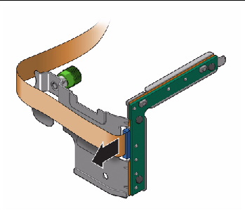
6. Disconnect the cable from the LED board (FIGURE 6-17).
FIGURE 6-17 Disconnecting Cable From the LED Board
7. Set the LED board aside on an antistatic mat.
8. Continue to Installing the LED Board.
1. Remove the replacement LED board from its packaging and place it on an antistatic mat.
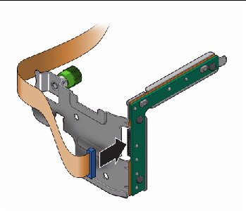
2. Connect the cable to the LED board (FIGURE 6-18).
FIGURE 6-18 Connecting Cable to the LED Board
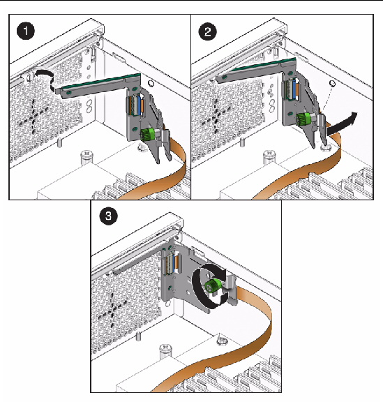
3. Insert the tab on the LED board into the slot on the chassis (FIGURE 6-19).
4. Swing the LED board right to the chassis and tighten the thumbscrew (FIGURE 6-19).
FIGURE 6-19 Inserting the LED Board Tab and Tightening the Thumbscrew
5. Route the LED board cable back into the cable guides.
6. Install the system fan assembly.
See Installing the System Fan Assembly.
8. Perform the following tasks to bring the server back online:
1. Prepare the server for PDB removal. See:
2. Remove the power supplies, the optical media drive, the hard drives, and the media bay assembly. See:
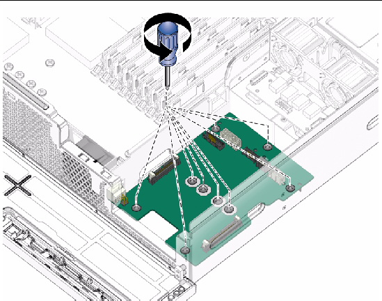
3. Remove the screws that secure the power board to the chassis (FIGURE 6-20).
FIGURE 6-20 Removing the PDB Screws
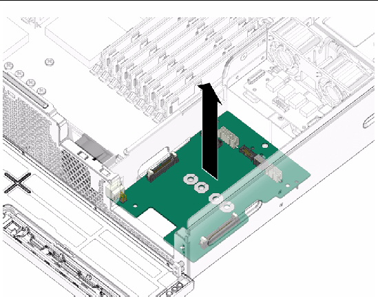
4. Lift the PDB out of the chassis and set it aside on an antistatic mat (FIGURE 6-21).
FIGURE 6-21 Lifting the PDB From the Chassis
5. Continue to Installing the Power Distribution Board.
1. Remove the replacement PDB from its packaging and place it on an antistatic mat.
2. Lower the PDB into the chassis, aligning the board’s holes with the standoffs in the chassis.
3. Install the screws firmly to secure the PDB to the chassis (FIGURE 6-20).
4. Install the media bay assembly, the hard drives, the optical media drive, and the power supplies. See:
5. Perform the following tasks to bring the server back online:
Copyright © 2010, Oracle and/or its affiliates. All rights reserved.