| Sun Blade T6340 Server Module Service Manual |
| C H A P T E R 4 |
|
Replacing Cold-Swappable Components |
This chapter describes how to remove and replace field-replaceable units (FRUs) that must be cold-swapped in the Sun Blade T6340 server module from Oracle.
The following topics are covered:
This section describes important safety information you need to know prior to removing or installing parts in the Sun Blade T6340 server module.
For your protection, observe the following safety precautions when setting up your equipment:
The following symbols might appear in this manual, note their meanings:

|
Caution - There is a risk of personal injury and equipment damage. To avoid personal injury and equipment damage, follow the instructions. |

|
Caution - Hot surface. Avoid contact. Surfaces are hot and might cause personal injury if touched. |

|
Caution - Hazardous voltages are present. To reduce the risk of electric shock and danger to personal health, follow the instructions. |
Electrostatic discharge (ESD) sensitive devices, such as the motherboard, hard drives, and memory cards require special handling.
Wear an antistatic wrist strap and use an antistatic mat when handling components such as drive assemblies, boards, or cards. When servicing or removing server module components, attach an antistatic strap to your wrist and the other end to a metal area on the chassis. Do this after you disconnect the power cords from the server module. Following this practice equalizes the electrical potentials between you and the server module.
Place ESD-sensitive components such as the motherboard, memory, and other PCB cards on an antistatic mat.
Before you can remove and replace internal components, you must perform the procedures in this section.
You can service the Sun Blade T6340 server module with the following tools:
Performing a graceful shutdown ensures that all of your data is saved and that the system is ready for restart. This section describes procedures for using the ILOM CLI or the ILOM web interface to shut down the system.
1. Log in as superuser or equivalent.
Depending on the nature of the problem, you might want to view the system status, the log files, or run diagnostics before you shut down the system. For more information, refer to:
Sun Integrated Lights Out Manager 2.0 Supplement for Sun Blade T6340 Server Modules, 820-3904. This document describes ILOM information specific to the UltraSPARC and the Sun Blade T6340 server module. It also provides command comparisons of the ALOM CMT and ILOM CLI command sets.
Refer to your Solaris system administration documentation for additional information.
3. Save any open files and quit all running programs.
Refer to your application documentation for specific information on these processes.
4. Shut down the Solaris OS using the shutdown (1M) command.
5. Use either the ILOM web interface, or the ILOM CLI, to finish the shut down sequence as described in the following sections.
You can also press the power button on the front of the server module to initiate a graceful shutdown.
From the ILOM web interface (FIGURE 4-1).
1. Select the System Information tab.
4. In the Actions menu, choose the “Prepare to Remove” option.
FIGURE 4-1 Powering Off the Server Module With the ILOM Web Interface

1. Switch from the system (host) console to the ILOM -> prompt by typing the #. (Hash-Period) key sequence.
2. At the ILOM -> prompt, type the server module power off command.
If the server module fails to power off at this point, you might want to force the issue.
1. At the ILOM -> prompt, type the set /SYS/ prepare_to_remove_action=true command and type y to confirm.
ILOM CLI, ILOM web interface, and ALOM-CMT command equivalents are described in Appendix F and Appendix G.
The blue blade ready to remove LED is illuminated.
The top white LED is the Locator LED. You can also set the white locator LED to blink:
Once you have located the server module, you can press the Locator LED to turn it off.
2. If a cable is connected to the front of the server module, disconnect it.
FIGURE 4-2 Disconnecting the Cable Dongle

| Note - If you are using the older 4-cable dongle (UCP-4), do not use the RJ-45 connector with the Sun Blade T6340 server module. Use the DB-9 connector for serial connections. |
3. Open both ejector levers simultaneously (FIGURE 4-3).
FIGURE 4-3 Removing the Sun Blade T6340 Server Module From the Chassis

4. While pinching the release latches, slowly pull the server module forward and out of the chassis.
|
|
Caution - Hold the server module firmly with both hands so that you do not drop it. The server module weighs up to approximately 19.8 pounds (9 kg). |
|
|
Caution - Do not stack server modules higher than five units tall. They might fall and cause damage or injury. |
FIGURE 4-4 Stack Five Server Modules or Fewer

5. Set the server module on an antistatic mat.
6. Attach an antistatic wrist strap.
When servicing or removing server module components, attach an antistatic strap to your wrist and the other end to a metal area on the chassis.
FIGURE 4-5 Antistatic Mat and Wrist Strap
7. While pressing the top cover release button, slide the cover toward the rear of the server module about an inch (2.5 mm).
8. Lift the cover off the chassis.
This section describes how to remove and replace DIMMs.
LEDs indicate if a DIMM requires replacement.
|
|
Caution - Ensure that you follow antistatic practices as described in Section 4.1.2, Electrostatic Discharge Safety. |
1. Perform the procedures described in Section 4.2, Common Procedures for Parts Replacement.
2. Locate the DIMMs that you want to replace (FIGURE 4-6).
The server module has a DIMM locate button on the motherboard. Press the DIMM locate button to illuminate the LEDs of the bad DIMMs.
FIGURE 4-6 DIMM Installation Rules

You can also use FIGURE 4-6 and TABLE 4-1 to identify the DIMMs that you want to remove.
|
FB-DIMM Installation Order[1] |
|||||
|---|---|---|---|---|---|
| Note - FB-DIMM names in ILOM messages are displayed with the full name, such as /SYS/MB/CMP0/BR0/CH0/D0. |
3. Note the DIMM locations so that you can install the replacement DIMMs in the same sockets.
4. Push down on the ejector levers on each side of the DIMM connector until the DIMM is released.

5. Grasp the top corners of the faulty DIMM and remove it from the system.
6. Place DIMMs on an antistatic mat.
See Section 2.2.1, Memory Configuration for complete memory configuration and installation rules.
|
|
Caution - The DIMM rules must be followed. The server module might not operate correctly if the DIMM rules are not followed. Always use DIMMs that have been qualified by Sun. |
1. Place the replacement DIMMs on an antistatic mat.
2. Remove any DIMM filler cards installed in the DIMM connectors in which you plan to install the new DIMMs.
3. Ensure that the connector ejector tabs are in the open position.
4. Line up a replacement DIMM with the connector.
Align the DIMM notch with the key in the connector.
a. Push each DIMM into a connector until the ejector tabs lock the DIMM in place.
b. Perform the procedures described in Section 4.10, Finishing Component Replacement.
The service processor controls the host power and monitors host system events (power and environmental). The service processor holds a battery for maintaining the Real Time Clock (RTC), and a socketed EEPROM for storing the system MAC addresses (and therefore the host ID).
|
|
Caution - The service processor card can be hot. To avoid injury, handle it carefully. |
1. Perform the procedures described in Section 4.2, Common Procedures for Parts Replacement.
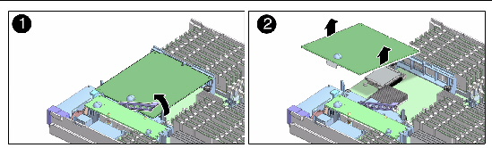
2. Lift up on the card ejector lever (FIGURE 4-8).
FIGURE 4-8 Removing the Service Processor

3. Slide the service processor out of the standoff bracket that holds the end of the service processor opposite the card connector.
4. Flip the service processor card over and place it on an antistatic mat.
5. Remove the system configuration PROM (NVRAM) (FIGURE 4-9) from the service processor card and place the PROM on an antistatic mat.
The socketed EEPROM attached to the Service Processor Card contains the system MAC addresses (and therefore the host ID).
The service processor also contains the ILOM configuration including the Service Processor IP addresses and ILOM user accounts, if configured. The MAC address (and host ID) will be lost unless the system configuration PROM (NVRAM) is removed from the old Service Processor card and installed in the replacement Service Processor Card. The ILOM configuration (IP address and user accounts) will be lost when the Service Processor Card is replaced.
The PROM does not hold the fault data, and the fault data will no longer be accessible when the service processor is replaced.
FIGURE 4-9 Removing the System Configuration PROM (NVRAM)
")
6. Retain the system configuration PROM to install it on the replacement service processsor card.
1. Remove the replacement service processor from the package and place it on an antistatic mat.
2. Install the system configuration PROM (NVRAM) that you removed from the faulty service processor.
The PROM is keyed to ensure proper orientation.
3. Insert the service processor edge into the standoff bracket and carefully align the service processor so that each of its contacts is centered on a socket pin (FIGURE 4-10).
FIGURE 4-10 Replacing the Service Processor

4. Push both rubber buttons firmly and evenly until the service processor is firmly seated in the connector socket.
5. Perform the procedures described in Section 4.10, Finishing Component Replacement.
|
|
Caution - Handle the components carefully to avoid damage. |
1. Perform the procedures described in Section 4.2, Common Procedures for Parts Replacement.
2. Remove the service processor from the chassis as shown in Section 4.4.1, Removing the Service Processor.
3. Place the service processor upside down on an antistatic mat.
4. Carefully use your fingernail to remove the battery (FIGURE 4-11) from the service processor.
FIGURE 4-11 Removing the Battery From the Service Processor

1. Remove the replacement battery from the package.
2. Press the new battery into the service processor (FIGURE 4-11) with the positive side (+) facing upward (away from the card).
3. Replace the service processor in the server module as shown in Section 4.4.2, Replacing the Service Processor.
4. Perform the procedures described in Section 4.10, Finishing Component Replacement.
5. Before you power on the host system, type the ILOM set /SP/clock datetime command to set the day and time.
For details about this command, refer to the Sun Integrated Lights out Manager 2.0 User’s Guide, 820-1188.
-> set /SP/clock datetime=10 Set ‘datetime’ to ‘102421532007.30’ -> show /SP/clock Targets Properties: datetime = Wed Oct 24, 21:53:38 2007 usentpserver = disabled ... |
| Note - Depending on how you ordered your server, the Sun Blade RAID 5 Expansion Module ships preinstalled in your server or as an option shipped separately. If your Sun Blade RAID 5 Expansion Module was shipped separately, see Section 4.6.2, Installing the Sun Blade RAID 5 Expansion Module. |
| Note - Avoid excess strain on the REM edges. Lift as close to the connector as possible. |
If you have a previously installed REM, save the configuration (save state) before removing it. Refer to the Sun Blade 6000 Disk Module Service Manual, 820-1703 and the Sun Blade 6000 Disk Module Administration Guide 820-4922
http://docs.sun.com/app/docs/prod/blade.6000disk~blade6000dskmod
Also refer to the Sun Adaptec RAID User’s Guide, 820-4708 for instructions on using the Java GUI to save the configuration of the existing REM.
1. Perform the procedures described in Section 4.2, Common Procedures for Parts Replacement.
2. Lift up on the REM ejector lever (FIGURE 4-12).
| Note - The REM’s external battery cable is still connected to the component side of the REM. Lift the REM slowly and only enough to disconnect the battery cable. |
3. Carefully lift the REM free from the connector and plastic standoff (FIGURE 4-12).
FIGURE 4-12 Removing the Sun Blade RAID 5 Expansion Module
4. Disconnect the 520 mm external battery cable from the component (bottom) side of the REM at J3 and also from the external battery tray (FIGURE 4-13).
FIGURE 4-13 Disconnecting the External Battery Cable from the Sun Blade RAID 5 Expansion Module

5. Set the REM aside on an antistatic surface.
1. Install the Sun Blade RAID 5 Expansion Module battery tray in internal hard drive slot HDD1 (top HDD slot).
See Section 4.6.3, Installing and Removing the Sun Blade RAID 5 Expansion Module Battery Tray
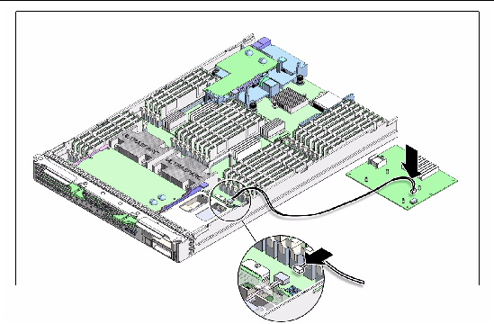
2. Connect the 520 mm battery cable to the component side of the REM at J3 and to the external battery tray (FIGURE 4-14).
FIGURE 4-14 Connecting the Battery Cable to the Sun Blade RAID Expansion Module
3. Slide the end of the REM opposite the connector under the tabs of the plastic standoff (FIGURE 4-15 Step 1).
4. Press down on the button to secure the connector in place (FIGURE 4-15 Step 2)
FIGURE 4-15 Installing the Sun Blade RAID 5 Expansion Module

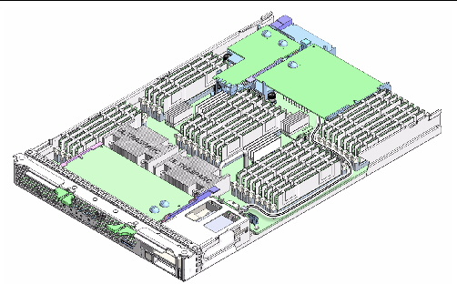
5. Route the Sun Blade RAID 5 Expansion Module 520 mm battery cable along the side of the memory, behind the SATA connectors at J9802 and J9803 (FIGURE 4-16).
FIGURE 4-16 Routing the External Battery Cable for a Sun Blade RAID 5 Expansion Module
6. Perform the procedures described in Section 4.10, Finishing Component Replacement.
Sun Blade RAID 5 Expansion Module receives battery support from a replaceable battery tray installed in place of the HDD1 internal hard drive.
|
|
1. Slide the module into the bay until the latch clicks in place (FIGURE 4-17.).
FIGURE 4-17 Installing the Sun Blade RAID 5 Battery Tray

2. Connect the 520 mm battery cable to the cable connector at the back of the Sun Blade RAID 5 Expansion Module battery tray (FIGURE 4-17).
3. Perform the procedures described in Section 4.10, Finishing Component Replacement.
1. Identify the physical location of the battery tray, which is in slot HDD1 (FIGURE 4-18).
FIGURE 4-18 Removing the Sun Blade RAID 5 Expansion Module Battery Tray
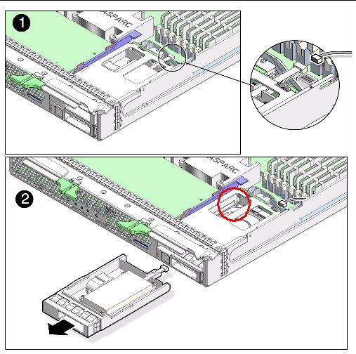
2. Disconnect the 520 mm battery cable from the REM battery tray connector (FIGURE 4-18).
3. Press down on the the battery tray latch (circled in red) on the upper left side of the module case, and slide the module straight out of the drive slot (FIGURE 4-18).
4. Set the battery tray aside on an antistatic surface.
See Appendix B for creating a bootable array. See Appendix C for nstalling the Solaris OS and the Sun Blade RAID 5 Expansion Module driver.
| Note - Avoid excess strain on the REM edges. Lift as close to the connector as possible. |
If you have a previously installed REM, save the configuration with the LSI Utility (lsiutil) before removing it. Refer to the Sun Blade 6000 Disk Module Service Manual, 820-1703 and the Sun Blade 6000 Disk Module Administration Guide 820-4922
http://docs.sun.com/app/docs/prod/blade.6000disk~blade6000dskmod
1. Perform the procedures described in Section 4.2, Common Procedures for Parts Replacement.
2. Lift up on the REM ejector lever (FIGURE 4-19).
3. Lift the REM free from the connector.
4. Lift the REM free from the plastic standoff.
FIGURE 4-19 Removing the RAID Expansion Module

5. Set the REM aside on an antistatic surface.
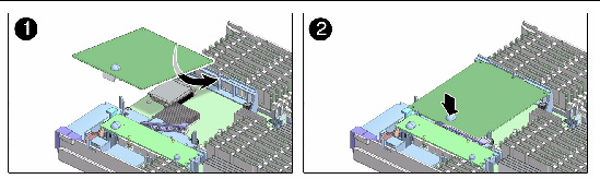
1. Slide the end of the REM opposite the connector under the tabs of the plastic standoff (FIGURE 4-20).
2. Press firmly on the rubber button on the top of the REM until its connector fully engages the connector on the motherboard.
FIGURE 4-20 Replacing the RAID Expansion Module
3. Perform the procedures described in Section 4.10, Finishing Component Replacement.
|
|
Caution - Handle the components carefully to avoid damage. |
|
|
Caution - The FEM can be hot. To avoid injury, handle it carefully. |
1. Perform the procedures described in Section 4.2, Common Procedures for Parts Replacement.
2. Lift the handle of the FEM ejector to release the FEM from the motherboard connector (FIGURE 4-21).
FIGURE 4-21 Removing a Fabric ExpressModule (FEM)

3. Lift the FEM free from the plastic standoff (FIGURE 4-21).
4. Place the FEM on an antistatic mat.
1. Remove the replacement FEM from the package and place it on an antistatic mat.
FIGURE 4-22 Replacing the Fabric ExpressModule (FEM)

2. Insert the FEM edge into the bracket and carefully align the FEM so that its contacts are centered on motherboard connector (FIGURE 4-22).
3. Press firmly on the rubber buttons on the top of the FEM until its connectors fully engage the connectors on the motherboard..
4. Perform the procedures described in Section 4.10, Finishing Component Replacement.
|
|
Caution - Handle the components carefully to avoid damage. |
1. Perform the procedures described in Section 4.2, Common Procedures for Parts Replacement.
2. Remove an installed Compact Flash module by pressing it down and then pulling it straight out from its connector on the server module’s motherboard (FIGURE 4-23).
FIGURE 4-23 Replacing a Compact Flash Module

3. Place the Compact Flash module aside on an antistatic surface.
4. Insert the new replacement Compact Flash module straight into the connector on the server module’s motherboard (FIGURE 4-23).
The Compact Flash module connector is keyed; the Compact Flash module will only fit in the correct orientation.
5. Firmly push the Compact Flash module straight into the connector, until the module is securely seated in the connector.
6. Perform the procedures described in Section 4.10, Finishing Component Replacement.
1. Place the cover on the chassis.
Set the cover down so that it hangs over the rear of the server module by about an inch (2.5 mm).
2. Slide the cover forward until it latches into place (FIGURE 4-24).
FIGURE 4-24 Replacing the Cover

|
|
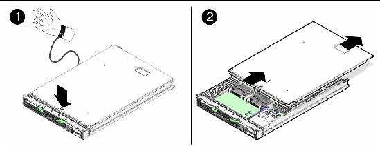
Caution - Hold the server module firmly with both hands so that you do not drop it. The server module weighs approximately 19.8 pounds (9 kg). |
1. Turn the server module over so that the ejector levers are on the right side.
2. Slide the server module into the chassis.
3. Close both latches simultaneously, locking the server module in the chassis.
You can either press the Power button to fully power on the server module, type the ILOM command start /SYS, or use the ALOM-CMT poweron command.
FIGURE 4-25 Inserting the Server Module in the Chassis

FIGURE 4-25 shows the server module being inserted into the chassis, and latches closing simultaneously.
| Note - The sever module power on process can take five or more minutes to complete, depending on the amount of installed memory, diagnostic level set, and possibly other factors. |
| Sun Blade T6340 Server Module Service Manual | 820-3902-12 |
Copyright © 2010, Oracle and/or its affiliates. All rights reserved.
 Installing the Sun Blade RAID 5 Expansion Module Battery Tray