| C H A P T E R 4 |
 Installing the SPARC Enterprise M4000 Server in a Rack
 |
This chapter describes how to mount a SPARC Enterprise M4000 server in a rack. The instructions cover Sun Rack 1000, Sun Rack 900, and Sun Rack II.
The following topics are in this chapter:
The M4000 server is designed for a standard 19-inch rack with a depth of 1000 mm or more. The M4000 is 6 rack units tall (6U) and weighs 84 kg (185 lb).
When mounted in a Sun Rack 900, the cabinet extender option is required to enable the rear door to close. See Mounting Specifications.


|
Caution - The M4000 server can weigh up to 84 kg (185 lb). Two people using a computer equipment lift are required to mount the server safely in the equipment rack. |

There are two rail kit options for M4000 servers. The following figure shows that the main visible difference between the two rail kits is the height of the rail brackets.
The installation procedure gives the installation steps for both styles of rail.
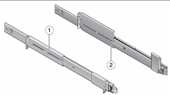
FIGURE 4-1 shows the contents of the version 1 rail kit. The version 2 rail kit is similar and uses the same assorted parts.
FIGURE 4-1 M4000 Server Rail Kit Contents
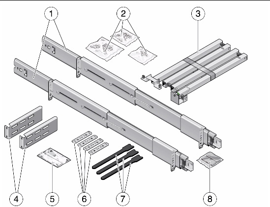
|
Bag of parts -M3 flathead screw (8), M5 cage nut (8), M5 flathead screw, washer (8) |
|
| Note - Not all parts in the rail kit will be used. For example, cage nuts are not used in Sun Rack 1000 or 900 racks. |
Shipping brackets are included in the rail kit. Installation of the brackets is optional.
FIGURE 4-2 Contents of the M4000 Shipping Bracket Kit
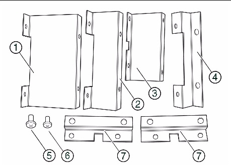
| Note - Different sizes of brackets are included to fit different racks, so not all parts in the kit will be used. |
Determine a location for the M4000 server in the equipment rack. The M4000 server is six rack units tall.

|
Caution - For rack stability, place the M4000 server at the lowest open location before filling in the higher areas. Keep the rack’s center of gravity as low as possible. |

| Note - The M4000 server rail kit includes a mounting guide template which can be used to determine hole locations for the rails in the rack. |
Instructions for Sun Rack 1000 and 900 start in Installing Slide Rails in the Rack.
For a Sun Rack II, you must first install cage nuts in the rack. You must also add nut bar brackets to the rails.
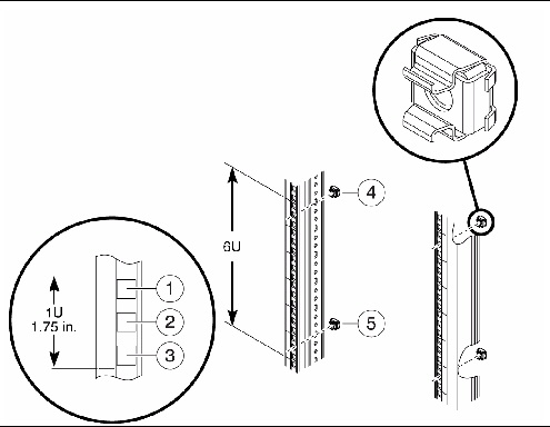
Screw hole numbers and rack unit numbers start from the bottom and work upwards. Note that two sizes of cage nuts are used in this procedure.
If you are not familiar with cage nuts, see Appendix A.
1. Install M6 cage nuts for standoffs.
a. Install cage nuts at screw hole #2 at U1 and screw hole #17 at U6 in the left front rack rail.
b. Repeat Step a for the right front rail.
The rear rails will not have standoffs. This procedure uses a total of four M6 cage nuts.
FIGURE 4-3 Cage Nut Hole Locations for the M4000 Server
2. Install M5 cage nuts for slide rails.
a. Install cage nuts at screw hole #6 at U2 and #10 at U4 in both front rack rails.
b. Repeat Step a for the rear rack rails.
This procedure uses a total of eight M5 cage nuts.
This procedure applies to Sun Rack II only.
 Attach nut bars to the front and rear brackets on each slide rail.
See FIGURE 4-4. Use two M2.5 flathead screws for each nut bar.
FIGURE 4-4 Attaching Nut Bars with Brackets
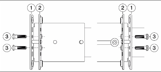
To identify the left and right rails:
1. Identify the locations for the slide rails in the rack (FIGURE 4-5).
The slide rails attach at the second and fourth rack units. The screw holes should align with the top hole of U2 and the bottom hole of U4.
FIGURE 4-5 Installing a Slide Rail
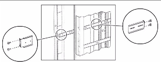
2. Starting with the front of the rack, hook the front bracket on the rack column.
The brackets on the slide rails have pins and hooks to hold them in place while they are being secured.
3. Slide the rear bracket horizontally to hook onto the rear rack column.
4. Install the remaining slide rail in the same manner.
5. Verify that the slide rails are at the same height.
6. Fasten each slide rail in place with four screws.
For version 1 slide rails, use this procedure to attach the inner slides to the sides of the server.
For version 2 slide rails, skip this procedure and go instead to Mounting the Server in the Rack.
1. If the inner slides are packed separately in the shipping kit, go to Step 3.
2. Remove the inner slides from the slide rails as follows.
a. Pull the inner slide out approximately 850 mm (34 in), until it locks in the fully extended position.
b. Release the slide rail by pressing the green tab on the inner slide, then pull the inner slide completely out of the slide rail.
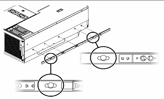
3. Attach the inner slides to the sides of the server.
a. Orient the flat side of the inner slide toward the server so that the pins on the side of the server pass through the holes on the inner slide (FIGURE 4-6).
b. Slide the inner rails toward the front of the server to lock them in place.
FIGURE 4-6 Securing a Slide to the Server

|
Caution - The anti-tilt bar or anti-tilt legs must be extended or the equipment rack will topple when the server is installed on the extended slide rails. |
1. Extend the anti-tilt bar or anti-tilt legs.
For details on extending the anti-tilt bar in a Sun Rack 1000, 900 or Sun Rack II, see Appendix B, Extending the Anti-Tilt Bar or Anti-Tilt Legs.
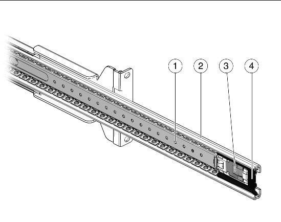
2. Extend the slide rails or bearing cars (FIGURE 4-7) until they lock in place.
FIGURE 4-7 Bearing Car in Full Forward Position Inside the Slide Rail
3. Place the forks of the computer equipment lift inside the plinth on the underside of the system.
The plinth protects the underside of the system and keeps the system from sliding off the computer equipment lift.
4. Attach the server to the slide rails with one of the following procedures.
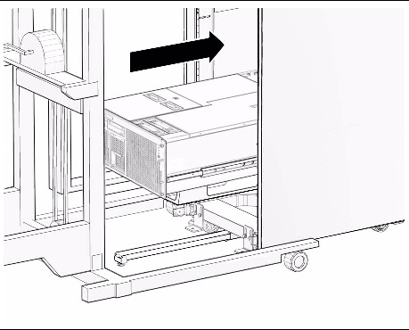
a. Raise the server and gently push it towards the equipment rack until the inner rails align with the slide rails.
b. Slide the inner rails into the slide rails until the inner rails lock into place.
FIGURE 4-8 Inserting Inner Slides in Version 1 Slide Rail Bearing Cars
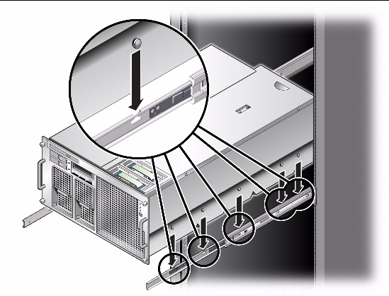
The slide rails have keyholes that fit over pins on the sides of the server. Labels are located on the side of each server to help identify the mounting points.
a. Raise the server and gently push it towards the equipment rack until the pins on the sides of the server are directly above the keyholes in the slide rails.
b. Lower the server so that the pins on the server enter the keyholes.
c. Push the slides towards the rear of the server to lock them in place.
FIGURE 4-9 Aligning Server Pins With Version 2 Slide Rail Keyholes
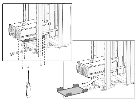
5. Remove the plinth from the bottom of the server (FIGURE 4-10).

|
Caution - Remove the plinth prior to sliding the server into the rack so that the server below is not damaged. |
There are eight (8) screws that secure the plinth to the bottom of each server.
a. Remove the two (2) front screws.
b. Loosen the remaining six (6) screws.
c. Slide the plinth toward the rear of the server less than an inch until the plinth is released from the screws.

|
Caution - The plinth weighs 2 kg (5 lb). To prevent injury, support the plinth upon release from the screws. |
d. Remove the six (6) loosened screws.

|
Caution - The rack stabilizer must be extended or the equipment rack will topple when the lifting device is withdrawn |

FIGURE 4-10 Example of Removing the Plinth
6. Withdraw the computer lifting device.
7. Slide the server into the cabinet.
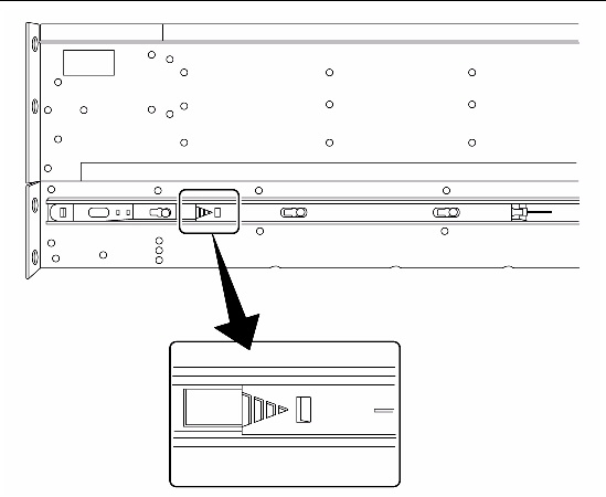
| Note - Labels are located on the sides of the server to assist in fully seating the server in the cabinet. |
FIGURE 4-11 Locking Mechanism on the M4000 Slide Rail
8. If you are installing the CMA at this time, proceed to Installing the Cable Management Arm.
If you are not installing the CMA, proceed to Step 9.
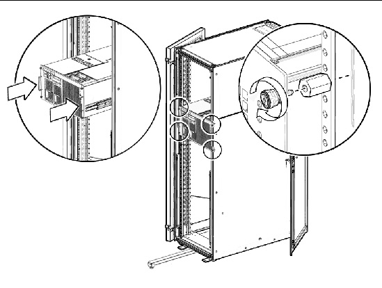
9. Secure the spacers at the front of the rack (FIGURE 4-12).
The spacer holes are located one hole above and below the server. The spacers should align with the captive screws on the front of the server.
FIGURE 4-12 Example of Spacers Aligned With Captive Screws
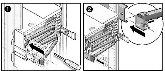
The cable management arm (CMA) for the M4000 server attaches to the left rear of the server.
1. Wind the CMA so that the springs are taut and positioned against the arm.

|
Caution - You must hold both ends of the CMA while it is taut to keep the spring-loaded arm from striking yourself or nearby equipment. |
2. Secure the small end of the CMA to the server by using the two (2) captive screws (FIGURE 4-13).
3. Secure the large end of the CMA to the rail on the same side of the rack.
The CMA attaches using a captive connector to hold it into position on the slide assemblies.
FIGURE 4-13 Installing the Cable Management Arm
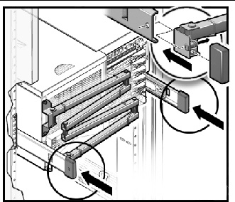
After securing the CMA to the M4000 servers, attach the provided end caps to the rails.
1. Attach the end caps onto the slide rails.
An end cap is attached to both the right and left rear rails (FIGURE 4-14).
| Note - If the CMA is not used, attach all end caps to the rails of the server. The M4000 server uses two end caps. |
FIGURE 4-14 End Caps on the M4000 Server Slide Rails
2. Connect the power cables to the rear of the server and secure them with the cable retention clamps.

|
Caution - Do not connect the power cables to a power source at this time. |
3. Run the power cables along the CMA and secure them in place with tie wraps.
The power cables and infiniband cables should hang loosely in a service loop behind the server or the CMA might not be able to fully retract.

|
Caution - To avoid the cables from bumping into the I/O cable connectors, do not twist the cables around the end of the CMA. |
FIGURE 4-15 Example of Bundling Cables in a Cabinet
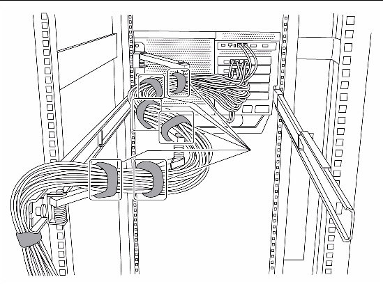
| Note - If additional attachment points are required to route the cables, install the optional bracket kit. See Installing the Cable Holding Brackets (Optional). |
4. Ensure that the server can slide in and out of the rack without dislodging the power cables.
FIGURE 4-16 shows how the CMA extends and retracts.
FIGURE 4-16 CMA Extended and Retracted on the M4000 Server
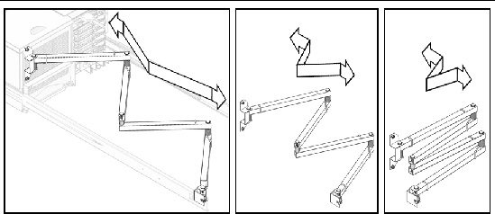
FIGURE 4-17 Securing the Server in the Rack
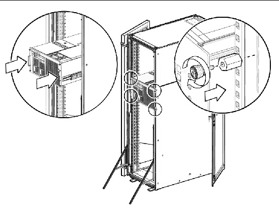
5. Slide the server into the rack.
6. Tighten the four (4) captive screws at the front of the server to secure the server in the rack.
7. Place the anti-tilt bar or anti-tilt legs in the original position.
If additional attachment points are required to route the cables, you can install the extra cable holding brackets included in the rail assembly kit. The parts needed for the cable holding brackets include the following:
These brackets can be used with or without the CMA for the server.
1. Extend the anti-tilt bar or anti-tilt legs on the rack.
2. Slide the server out of the cabinet several inches for access to the rear of the cabinet.
3. Attach the cable holding brackets on the rack column (FIGURE 4-18), as follows.
| Note - Brackets can be installed on both sides, on one side only (right or left side), or two on one side, as desired. |
a. For the Sun Rack II, attach two cage nuts to the rack column.
If you are not familiar with cage nuts, see Appendix A.
b. Use two screws to attach the bracket to the rack column.
FIGURE 4-18 Installing the Extra Brackets in a Sun Rack 1000
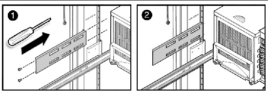
4. Insert hook and loop straps in the desired slots of the bracket to hold back cables.
Built-in cutouts along the sides of the Sun cabinet can also be used to insert hook and loop straps to hold back cables, as desired.
5. Slide the server into the rack.
6. Place the anti-tilt bar or anti-tilt legs in the original position.

Copyright © 2009, 2011, Oracle and/or its affiliates. All rights reserved. FUJITSU LIMITED provided technical input and review on portions of this material.