JavaScript is required to for searching.
Skip Navigation Links
Exit Print View
Sun Netra 6000 Modular System HTML Document Collection
search filter icon
search icon

Document Information

Using This Documentation

Product Notes

Related Documentation

Feedback

Access to Oracle Support

Installation

Preparing Your Site Before the System Arrives

Modular System Overview

Supported Racks

Location Restrictions for DC Models

Aisle Clearance for Service

AC Power Requirements

Determining DC Power Requirements

Important Cautions for DC Power Sources

Power Calculator

DC Power Specifications

L/R Ratio Impact on DC Power System Stability

Environmental Requirements

Airflow Requirements

Acoustic Noise Emissions

Weight and Size Specifications for Moving and Lifting

Preparing to Install the Modular System

Gather Required Tools and Equipment

Remove the Shipping Carton

Verify Shipment Contents

Note the CMM MAC Address

Installing the Chassis Into Your Rack

Depopulating the Chassis

Mounting the Chassis in a Rack

Repopulating the Chassis

Connecting To and Powering On the Modular System

Role of Oracle ILOM During Installation

Connectivity Choices

CMM IP Address Configuration

Connecting Data and Management Cables

Powering On the Modular System

Log Into the CMM Through the SER MGT Port

Configure the CMM NET MGT Port With a Static IP Address

Configure the IP Addresses Using Your DHCP Server

Identify the IP and MAC Addresses

Log Into the CMM Through the NET MGT Port

Change the CMM ILOM root Account Password

Installing Shipping Brackets on a Sun Rack 1000

Install Shipping Brackets

Remove Shipping Brackets

Remote Management (ILOM)

Understanding Oracle ILOM on the Modular System

Oracle ILOM Overview

Oracle ILOM 3.0 Features Specific to the Modular System

Configuring CMM ILOM

Logging Into and Out of CMM ILOM

Performing Common CMM ILOM Configuration Tasks

Viewing and Configuring IP and MAC Addresses

Managing the CMM Clock

Administering the Modular System (CMM ILOM)

Managing the Chassis Using the CLI

Accessing Server Modules (CMM ILOM)

Interpreting Sensors

Sensor Overview

Display Sensor Readings (CLI)

Chassis Sensors

Fan Sensors

Power Supply Sensors

NEM Sensors

Server Module Sensors

Identifying SNMP Trap and PET Event Messages

SNMP Traps

PET Event Messages

Service

Monitoring Faults

Understanding Fault Management

Monitoring Faults (LEDs)

Monitoring Faults (Oracle ILOM)

Preparing for Service

Component Types and Service Classifications

Differences Between Chassis Models and Their Replacement Components

Determine if a Chassis Is A90-B or A90-D (CLI)

Determine if a Chassis Is A90-B or A90-D (Web Interface)

Gather Required Tools

Prevent ESD Damage

Power Off the Server Modules and Storage Modules

Power Off Components in the Chassis

Removing Power From the Chassis

Removing the Chassis From the Rack

Replacing CRUs

Replacing a Power Supply

Replacing a Front Fan Module (AC)

Replacing a Server or Storage Module

Replacing the FIM

Replacing a PCI EM

Replacing a NEM

Replacing a Rear Fan Module

Replacing the Fan Board

Replacing the CMM

Replacing FRUs

Replacing the Midplane

Replacing an Internal Power Cable (AC)

Replacing the DC Input Unit

Replacing a DC Adapter Tray

Returning the Modular System to Operation

Reinstalling the Chassis Into a Rack

Applying Power to the Chassis

Verify Modular System Functionality

Glossary

Index

Modular System Overview

The modular system is a NEBS-compliant, rackmountable chassis that accommodates a variety of compute components such as blade servers (server modules), disk blades (storage modules), PCI EMs, and NEMs. Components can be configured to interact or to operate as separate entities.

The modular system supports mixing and matching of components. You can install server modules that are based on SPARC processors along with server modules based on Intel processors.

Each server module runs an independent operating system, and operating systems can be mixed and matched.

When the configuration of components is complete, the chassis and components become an integrated modular system.

There are two modular system models:

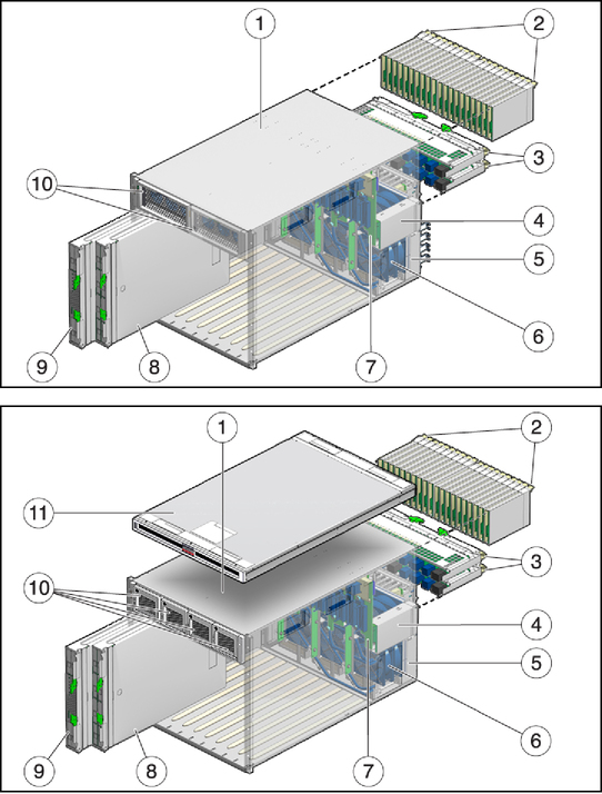
image:Illustration of modular components in the AC model and the DC model.
No.
Name
Description
1
Modular system chassis
AC model is 10U high, up to four supported in a 42U rack.

DC model is 11U high, up to three supported in a 42U rack.

Both models provide the following:

  • 10 vertical slots (front) for installation of server and storage modules

  • Hot-swappable power supplies (AC has two. DC has four)

  • CMM (rear)

  • 20 vertical slots (rear) for PCI EMs

  • 2 horizontal slots (rear) for NEMs

  • 8 hot-swappable fan modules (rear)

  • System status indicators (front and rear)

  • Midplane (internal) that interconnects components through industry-standard PCIe, SAS, SATA, and Ethernet protocols

2
PCI EMs
Up to 20 supported in the chassis. PCI EMs are based on the PCI Express industry-standard form factor and offer I/O features such as Gigabit Ethernet, Fibre Channel, and InfiniBand (supported I/O features differ, based on the server modules installed).

Each server module can be associated with up to 2 PCI EMs.

3
NEMs
Up to 2 supported in the chassis. Each NEM connects to all 10 server and storage module slots. NEMs provide 10/100/1000 Ethernet, SAS connectivity to storage modules, and 10GbE Ethernet ports.

Note - Most NEM functions, other than the 10/100/1000 Ethernet port, require a matching REM or FEM mounted on the server module motherboard before the server module can use that function.


4
Chassis management module (CMM)
A service processor for monitoring and managing components in the chassis. The CMM is preinstalled with Oracle ILOM software.

Note - Each server module has its own service processor that operates independently of the CMM. Storage modules do not have a service processor. The CMM provides a limited set of commands for managing storage modules.


5
Power receptacles
  • AC model – 4 power receptacles with power cord retention clips.
  • DC model – Blank panel.

6
Fan modules
6 redundant fan modules installed in the rear of the chassis.
7
Midplane
Inside the chassis, the midplane interconnects all the modular system components. The midplane supports industry-standard protocols such as PCIe, SAS, SATA, and Gigabit Ethernet.
8
Storage modules
Provide additional storage capacity to the modular system. The total number of supported storage modules depends on the model purchased. Refer to the storage module documentation for details.

Note - Sometimes storage modules are referred to as disk blades or disk modules.


9
Server modules
Up to 10 supported in the chassis. Server modules provide the following:
  • Motherboard with an UltraSPARC or Intel processor, and industry standard FB-DIMMs

  • SP that runs the Oracle ILOM software

  • Hard drives

  • Support for the addition of REMs

  • Support for the addition of FEMs that are needed when certain NEMs are installed in the chassis

Each server module is independent, so both SPARC and Intel server modules can be installed, each having its own operating system (Oracle Solaris OS, Linux, based on what is supported for the server module).


Note - Sometimes server modules are referred to as blade servers.


10
Power supply modules
  • AC model – 2 installed in the front of the chassis with power receptacles in the rear. Each power supply module has an integrated, replaceable fan module.
  • DC model – 4 installed in the front of the chassis with power connections at the rear. Each power supply module has an integrated, non-replaceable fan module.

11
DC input unit
(Only on DC models) Provides the DC input terminals by which the DC input power cables are connected and includes Telco Alarm LEDs at the front of the chassis.
n/s
REMs
Provide HBA functionality on some blade servers. A REM mounts to a REM connector on the server module motherboard. Different RAID levels are supported, based on the REM purchased.
n/s
FEMs
Installed on the server module, FEMs enable server modules to use the 10GbE connections provided by certain NEMs. NEMs and the corresponding FEMs operate as a matched set.
n/s
Status LEDs
Located on the front and rear of the chassis. These indicators provide a visual status of the modular system through status OK, fault, temperature failure, and locate LEDs.
Related Information