
This chapter describes how to remove and replace all GT Graphics Subsystem
assemblies designated as Field Replaceable Units (FRUs).
The procedures and illustrations in this chapter show you how to remove and
replace:
-
GT SBus Adapter Board (in the system unit)
-
Graphics Tower printed circuit boards
-
Graphics Tower power supply
-
Graphics Tower fan assembly
Caution -

Before removing any panels or subassemblies, follow the "System
Power-Down" procedures on page 72.
Before powering up, make sure the equipment is installed according to the
Hardware Installation Manual for the GT Graphics Subsystem, 800-5258. Power-up
the system in the following order:
1.
The monitor
2.
The Graphics Tower
3.
External drives (if any)
4.
The system unit
The ac power switches are "ON" when the "1" is pressed. Figure 4-1 shows
the location of all system power switches.
Note -
If the system is not powered-up in the above sequence, the system unit
openboot power-on sequence will fail to properly probe and initialize the GT
Graphics Subsystem.
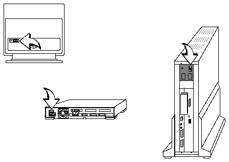
Figure 4-1
System Power Switches
To turn off the power when your system is working normally, become
superuser and save all your work, as described in the following steps:
Note -
For additional information about superuser passwords, see "Becoming
Superuser" in Chapter 2 of the, Sun System and Network Manager's Guide.
1. Save all your work.
See the Sun System User's Guide for more information about ending a work
session and saving your files. If you do not save your work, you could lose
it when you switch off the power.
2. Return to the Sun OS or Solaris operating system environment and
become superuser.
Type: su and press Return.
3. Type your superuser password and press Return.
4. Suth down the system.
For the SunOS 4.x operating system, type the following:

For the Solaris 2.x operating system, type the following:

5. After shutdown, you should get the following message:

When this message appears, you can safely turn off the power to your
system, as described in the next step.

6. Turn off the power in sequence to:
a. External drives (if any)
b. System unit
c. Color monitor
d. Graphics Tower
Note -
To end a work session and save your work when your system does not
respond to the mouse, you need to use a different procedure.
1. Press L1-a (or Stop-a for type 5 keyboards) to enter the PROM monitor
command mode. The monitor command prompt is indicated on the screen
with a "greater than" symbol ().
2. Type n followed by a carriage return.
3. When you see the message ok on the screen, type sync followed by a
carriage return.
The sync command attempts to save your work.

After typing the above commands, turn off the power as described in step 6
above.
Removal and replacement of the color monitor consists of disconnecting and
reconnecting cables. Follow these steps:
Monitor Removal
1. Power-down the entire system.
See "System Power-Down" on page 72.
2. Disconnect the Video cable from the monitor.
See Figure 4-2 for cable identification. Turn the two connector screws
counter-clockwise to disconnect the connector.
3. Disconnect the Power cable from the monitor.
Monitor Replacement
4. Make sure that the entire system is powered down.
5. Connect the Video cable to the monitor.
See Figure 4-2.
6. Connect the Power cable to the monitor.
7. Power-up the system.
See "System Power-Up" on page 70.
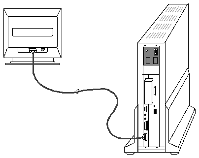
Figure 4-2
GT Graphics Subsystem Video Cable
The GT SBus Adapter Board is in the system unit. To remove and replace the
GT SBus Adapter Board:
Removal
1. Power down the entire system.
See "System Power-Down" on page 72. Leave the system unit power cable
plugged in.
2. Disconnect the host adapter cable from the system unit rear panel.
The host adapter cable connects between the GT SBus Adapter Board in the
system unit and the Graphics Processor Front End Board in the Graphics
Tower.
3. Remove the system unit top cover.
The top cover attaches to the chassis at the front with molded plastic tabs.
Push the cover forward to release the front cover from the points of
attachment to the chassis.
a. Remove the two screws holding the cover to the back panel.
See Figure 4-3.
b. Grasp the sides of the cover from the rear and tilt the cover until the
protector loop clears the chassis.
c. Gently push the cover forward about 1/2 inch (13 mm) so that the
plastic tabs clear the chassis.
d. Remove the cover by lifting vertically.
Caution -

The plastic tabs at the bottom of the cover are fragile. Be sure the
tabs clear the chassis before removing the cover.

Figure 4-3
Remove the System Unit Top Cover
4. Remove the GT SBus Adapter Board.
a. Gently lift up on the handle on the SBus-end of the board to unplug
the board from the socket.
The SBus-end of the board is the end furthest away from the system unit
back panel.
b. Slide the board at an angle out of the system unit back panel.
1. Make sure that the system unit power is OFF.
2. Install the replacement GT SBus Adapter Board into the system unit.
Make sure that the mounting plate on the GT SBus Adapter Board hooks
into the slot on the system unit back panel.
a. Slide the GT SBus Adapter Board at an angle into the system unit back
panel.
b. Align the plug with the socket and gently press down on the handle to
plug the board into the socket.
See Figure 4-4.

Figure 4-4
Align the Plug with the Socket.
3. Replace the system unit top cover.
Caution -

Holding the cover at angles greater than 30 degrees can prevent
insertion of the tabs into the tab slots. Once the tabs are in the slots, raising the
cover to angles greater than 30 degrees can break the tabs.
a. Align the cover to the chassis.
Hold the cover at an angle of 30 degrees relative to the chassis and gently
guide the plastic tabs on the cover into the tab slots on the front of the
chassis. Continue to hold the cover with your hands.
b. Lower the cover onto the chassis.
Slowly lower the cover onto the chassis and be sure the protector loop
clears the disk drive and seats into the protector loop on the bottom of
the chassis.
c. Insert and tighten the two screws that hold the top cover to the back
panel.
Warning -

Do not power up the system unit without replacing the cover and
securing it. Failure to take this precaution may result in personal injury and
system damage.
4. Re-connect the host adapter cable to the system unit.
5. Power up the system.
See "System Power-Up" on page 70.
6. Re-run the diagnostics.
See "SunDiag Diagnostics" on page 46.
The following steps describe how to replace the Graphics Tower printed circuit
boards: Graphics Processor Front End, Graphics Processor Rendering Pipeline,
and Frame Buffer.
Caution -

Springfingers are metal strips that are installed between the edge of
the printed circuit board and the outer panel to reduce RFI emissions. Serrated
metal fingers protrude from either side of the strip.
Installation of a board without springfingers may affect FCC compliance. Sun
will no longer be responsible for FCC compliance if a board without
springfingers is installed in the tower.
When removing and replacing boards with springfingers, check the condition
of the insulator strip/shields and replace if damaged. Contact your customer
support center for information on how to obtain additional insulator strips or
shields.
1. Power down the entire system.
See "System Power-Down" on page 72.
2. Remove the cables from the cable management brackets on the rear of the
Graphics Tower.
See Figure 4-5.
3. Remove the cable brackets from the Graphics Tower.
Pivot the brackets off of the plastic rails as shown in Figure 4-5.
4. Unplug the power cable from the rear of the Graphics Tower.
5. Disconnect the signal and video cables from the Graphics Tower.
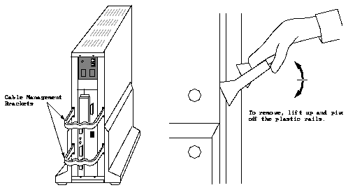
Figure 4-5
Graphics Tower Cable Management Brackets
6. Remove the foreplane EMI cover.
See Figure 4-6. Loosen the four screws with a flat blade screwdriver. The
screws are captive and cannot be completely removed.
7. Remove the foreplane connector.
The foreplane connector connects the Frame Buffer Board to the Graphics
Processor Rendering Pipeline Board. See Figure 4-6. Loosen the four screws
with a flat-blade screwdriver. The screws are captive and cannot be
completely removed.
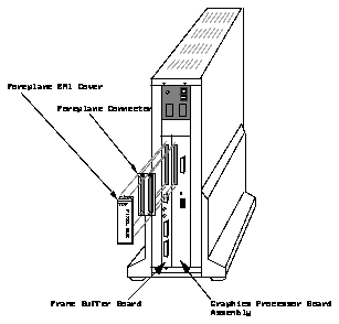
Figure 4-6
Foreplane EMI Cover and Connector
Removing the Frame Buffer Board
1. Remove the foreplane EMI cover and foreplane connector.
See page 80.
2. Locate the Frame Buffer Board.
The Frame Buffer Board is the left-most board when viewing the Graphics
Tower from the rear. See Figure 4-6.
3. Use a 2mm hex wrench to remove the two hex screws at the top and
bottom of the board.
See Figure 4-7.
4. Push the two board ejection levers out to unseat the board from the
backplane connectors.
Push the top lever up and the bottom lever down. See Figure 4-7.
5. Slide the board out of the chassis.
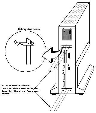
Figure 4-7
Graphics Tower Printed Circuit Board Removal
Removing the Graphics Processor Rendering Pipeline and Graphics Processor
Front End Boards
The Graphics Processor Rendering Pipeline Board and the Graphics Processor
Front End Board are attached together as a single assembly. To replace either
board, you first remove the assembly, then disassemble the two boards, as
described below.
1. Remove the foreplane EMI cover and foreplane connector.
See page 80.
2. Locate the Graphics Processor board assembly.
See Figure 4-6 on page 83.
3. Use a 2mm hex wrench to remove the four hex screws at the top and
bottom of the assembly.
See Figure 4-7 on page 85.
4. Push the two board ejection levers out to unseat the assembly from the
backplane connectors.
Push the top lever up and the bottom lever down.
5. Slide the assembly out of the chassis.
6. Remove the Front End Board from the seven Nylon snap-in standoffs.
Gently pinch the top of the standoff with a pair of long-nose pliers to allow
the standoff to pass through the hole in the Frame Buffer Board, as shown
below. Also, see the assembly diagram, Figure 6-5 on page 117.
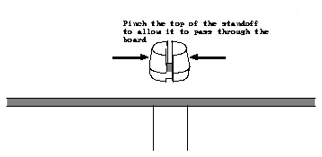
1. Make sure that the Graphics Tower power is OFF.
2. Install the replacement printed circuit board or board assembly into the
Graphics Tower.
Insert the board with the component side facing to the right side of the
tower.
If you are replacing either the Graphics Processor Rendering Pipeline Board
or the Graphics Processor Front End Board, you must first re-assemble the
two boards. Align the inter-board connectors and press the Front End Board
onto the seven snap-in standoffs, as shown in the assembly diagram, Figure
6-5 on page 117.
Push the board or assembly into the chassis slide rails until it is seated into
the backplane connectors.
3. Secure the board to the chassis with the two hex screws.
Use a 2mm hex wrench.
4. Re-attach the foreplane connector to the Frame Buffer Board and Graphics
Processor Rendering Pipeline Board.
See Figure 4-6 on page 83.
5. Re-attach the foreplane EMI cover.
See Figure 4-6 on page 83.
6. Re-connect the host adapter cable to the Graphics Tower.
7. Re-connect the video cable to the Graphics Tower.
8. Reinstall the cable management brackets.
See Figure 4-5 on page 81. Snap the cables into the brackets, if required.
9. Make sure that the Graphics Tower power switch is OFF, then plug in the
power cable.
10. Power up the system.
See "System Power-Up" on page 70.
11. Re-run the diagnostics.
See "SunDiag Diagnostics" on page 46.
To remove the power supply or fan assembly or to gain access to the
backplane, you must first remove the Graphics Tower trim, consisting of
To remove the Graphics Tower legs:
1. Power down the system and disconnect the power cable from the
Graphics Tower.
2. Disconnect the interface cables.
3. Remove the cable management brackets.
See Figure 4-5 on page 81.
4. Place a pad or cushion on a flat work surface to protect the tower from
scratches.
Place the tower on its side on the work surface.
Note -
The GT Graphics Subsystem tower weighs about 40 pounds (18 kg).
Having two people available makes the operation easier and safer.
5. Remove the air filter from the slot at the base of the tower.
6. Locate and remove the two round plastic covers on the legs.
See Figure 4-8. Push in on the small recessed dot on the cover, causing the
cover to protrude, then remove the cover.
7. Using a 10mm nut driver or a flat-blade screwdriver, remove the two
screws that attach the leg to the tower.
Remove the leg.
8. Turn the tower over and repeat steps 6 and 7 to remove the leg from the
other side.
Caution -

Do not place the tower in the vertical position without the support
legs installed.
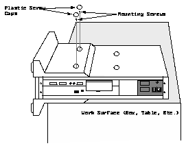
Figure 4-8
Graphics Tower Leg Mounting Hardware
To remove the louvered top cover:
1. Remove the Graphics Tower legs.
See "Removing the Legs" on page 88.
2. Turn the tower around so you are facing the ON/OFF switch.
3. Remove the four M4 slotted, hex-head securing screws that secure the end
of the cover to the tower.
See Figure 4-9.
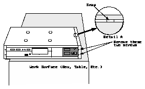
Figure 4-9
Removing the Louvered Top Cover
4. Locate the snap detail on the edge of the cover that secures the middle
part of the cover to the top of the tower.
See Detail A in Figure 4-9.
5. Insert a flat-blade screwdriver between the louvered top cover and the
side of the tower.
6. Gently raise the screwdriver to release the snap.
See Figure 4-10.
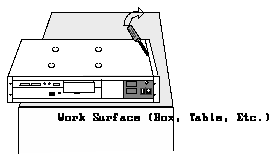
Figure 4-10
Release the Top Cover Snap
7. Turn the tower over.
Repeat steps 4 through 6 to release the second snap on the other side of the
top cover.
8. Gently pivot the cover about 30 degrees upward and slide the cover
toward you.
See Figure 4-11.
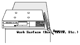
Figure 4-11
Removing the Louvered Cover
To remove the Graphics Tower front bezel, you must first remove the louvered
top panel as described on page 90.
To remove the front bezel:
1. Rotate the Graphics Tower so that you are facing the front side.
The Graphics Tower front side is the side with the GT Graphics Subsystem
emblem.
2. Release the front bezel snap detail in the same manner as described in
steps 4 through 6 of the previous procedure.
See page 91.
3. Pivot the bezel outward and pull it away from the tower to remove it.
See Figure 4-12.
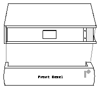
Figure 4-12
Removing the Front Bezel
Remove the backplane EMI cover only if you need to access the backplane.
To remove the EMI cover, you must first remove the louvered top panel, as
described on page 90, and the front bezel, as described on page 92.
To remove the EMI cover and expose the backplane:
1. Remove the two M4 \xb4 0.7 screws that hold the EMI cover in place.
See Figure 4-13.
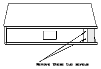
Figure 4-13
Removing the EMI Cover Mounting Screws
2. Pivot the EMI cover about 30 degrees outward and away from the
backplane.
See Figure 4-14.
3. Pull the EMI cover upward until the locking tabs are free from the bracket
in the base.

Figure 4-14
Removing the Backplane EMI Cover
After replacing the power supply/fan module or accessing the backplane,
replace the tower trim (EMI cover, bezel, and louvered panel) as described
below. See the assembly diagram, Figure 6-3 on page 114.
1. Insert the EMI cover tabs into the slots in the bracket on the tower base.
Press the cover into place.
2. Replace the screws removed in Step 1 of "Removing the Backplane EMI
Cover" on page 94.
3. Engage the bezel locking tabs in the tabs on the bottom louvered panel.
Pivot the bezel toward the EMI cover until the bezel is in place.
4. Insert the tabs on the louvered top panel you first removed into the
locking tabs on the bezel.
Gently press until the top panel is in place.
5. Replace the two screws removed in Step 3 of "Removing the Louvered
Top Cover" on page 90.
6. Re-install the legs.
See Figure 4-8 on page 89.
7. Clean and re-install the air filter.
See "Graphics Tower Air Filter Cleaning or Replacement Procedure" on
page 106.
Note -
To replace either the power supply or the fan assembly, you must
remove the power supply/fan module. The fan assembly is mounted to the
bottom of the power supply assembly.
To remove the power supply/fan module:
1. Remove the Graphics Tower air filter, legs, louvered top panel, bezel, and
EMI cover.
See "Removing the Graphics Tower Trim" on page 88.
2. Remove the screws that secure the red +5V and black ground cables to the
backplane bus bars.
See Figure 4-15.
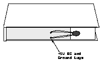
Figure 4-15
Disconnect the +5V and Ground Cables
3. Disconnect the eight-pin Molex-type connector that provides dc voltages
to the backplane.
See Figure 4-16.
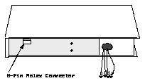
Figure 4-16
Disconnect the Eight-Pin Molex Connector
4. Disconnect the two-pin power sense connector located near the eight-pin
connector.
5. Remove the two M4 screws that are located on each end of the power
supply module, closest to the backplane.
See Figure 4-17.
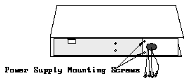
Figure 4-17
Remove the Power Supply/Fan Module Mounting Screws
Note -
The following steps are much easier if you have a second person to
assist you.
6. Loosen the side panels and have someone hold them outward.
See Figure 4-18.
7. Grasp both ends of the power supply/fan module and lift it away from
the cardcage.
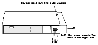
Figure 4-18
Removing the Power Supply/Fan Module
Removing the Fan Assembly
To remove the fan assembly from the power supply/fan module:
1. Remove the power supply/fan module from the Graphics Tower.
See "Removing the Power Supply/Fan Module from the Graphics Tower"
on page 97.
2. Remove the 14 screws that secure the fan assembly to the power supply
module.
See the assembly diagram, Figure 6-6 on page 118.
3. Disconnect the main dc power connector from the fan tray printed circuit
board.
See the assembly diagram, Figure 6-6 on page 118.
4. Remove the fan assembly.
Removing the Power Supply from the Module
To remove the power supply from the power supply/fan module:
1. Remove the power supply/fan module from the tower.
See "Removing the Power Supply/Fan Module from the Graphics Tower"
on page 97.
2. Remove the fan assembly from the module as described above.
3. Disconnect the ac power and power good sense connectors from the ac
convenience module.
See the assembly drawing, Figure 6-7 on page 120.
4. Turn the power supply over and remove the screws that secure the power
supply to the top of the module.
5. Slide the power supply out of the module.
Feed the dc cables through the opening at the end of the tower.
Re-Installing the Power Supply/Fan Module
To re-install the power supply/fan module:
1. Have someone pull the side panels outward.
2. Grasp both ends of the power supply and insert it into the opening.
See Figure 4-18 on page 100.
3. Attach the power supply with two M4 screws on each end of the power
supply.
4. Re-connect the two-pin power sense connector.
5. Re-connect the eight-pin Molex connector.
See Figure 4-16 on page 98.
6. Re-attach the red +5V and black ground cables to the backplane bus bars.
See Figure 4-15 on page 97.
7. Replace the enclosure EMI cover, bezel, louvered top panel, and legs.
See "Re-Installing the Graphics Tower Trim" on page 96.
To remove the Graphics Tower backplane:
1. Remove the printed circuit boards from the Graphics Tower.
See "Replacing the Graphics Tower Printed Circuit Boards" on page 80.
2. Remove the Graphics Tower trim.
See "Removing the Graphics Tower Trim" on page 88.
3. Remove the two screws that secure the bottom louvered panel.
The bottom louvered panel attaches the same as the top louvered panel (see
Figure 4-9).
4. Remove the two remaining screws that hold the side panels in place.
See Figure 4-19. The other two screws were removed with the tower legs.
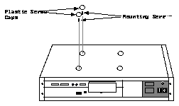
Figure 4-19
Side Mounting Screws
5. Turn the tower over and remove the other side panel.
Caution -

To prevent bending the second side panel when turning the tower
over, make sure that you turn the tower end-for-end.
6. Remove the power supply/fan module.
See "Removing the Power Supply/Fan Module from the Graphics Tower"
on page 97.
7. Disconnect all the cables from the backplane.
8. Remove the eight screws that secure the backplane to the card cage.
See the illustrated parts breakdown, Figure 6-9 on page 124.


