
Make sure you have read the Preface for the safety precautions and Chapter 1 for an overview of the installation and replacement procedures and the list of required tools before proceeding with this chapter.
Complete the procedures in the following sections to prepare your system for installing or replacing a 5.0 Gbyte 8 mm tape drive.
You must power off the SPARCcenter 2000 system before proceeding with the following sections. Refer to the SPARCcenter 2000 Installation Manual (P/N 800- 6975-xx) for instructions on safely powering off the cabinet.
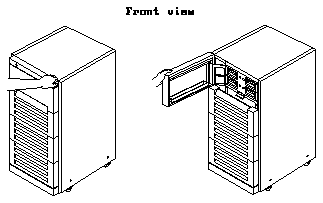
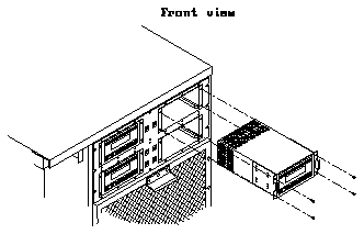
Pull on the right side of the top front panel on the SPARCcenter 2000 system to open that panel (see Figure 4-1).
Caution -

Follow these instructions to unpack and inspect the drive:
Placing the drive on the bag will prevent static discharge from accumulating in the device.
If damaged, keep all contents and packing materials for the carrier's agent to inspect.
The shipping container should have the following items:
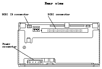
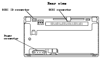
A jumper is a small sleeve that slides over two adjacent pins in the SCSI ID connector to provide an electrical connection. If there are jumpers installed on the SCSI ID connector, remove the jumpers using the needle-nosed pliers.
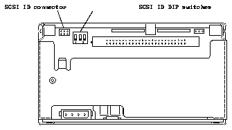
Figure 4-2 Location of the SCSI ID Connector and the SCSI ID DIP Switches on the 5.0 Gbyte 8 mm Tape Drive (Rear View)
Follow these instructions to install a 5.0 Gbyte 8 mm tape drive in your SPARCcenter 2000 system.
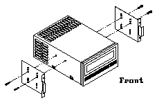
If you are replacing the 5.0 Gbyte 8 mm tape drive, you can use the mounting brackets you removed from the old drive.
When installing the mounting brackets to the tape drive, make sure the following items are done properly:

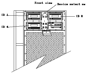
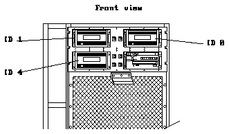
There are three possible locations for the 5.0 Gbyte 8 mm tape drive in the SPARCcenter 2000 system (see Figure 4-4).
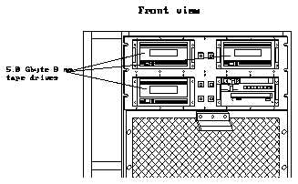
Figure 4-4 Locations for 5.0 Gbyte 8 mm Tape Drives in SPARCcenter 2000 System (Front View)
The address cable for the tape drive will be plugged into the device select switch on the side of the drive bay where you are installing the drive. Figure 4-5 shows the device select switch on the left side of the tape drive; tape drives installed in the left drive bays will have the device select switch on the right side of the drive.
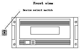
Figure 4-5 Possible Location for the Select Switch for the 5.0 Gbyte 8 mm Tape Drive (Front View)
Orient the address cable so that the pin 1 portion of the address cable connector plugs into the pin 1 connector on the SCSI ID connector at the rear of the 5.0 Gbyte 8 mm tape drive.
The SCSI address for the tape drive will vary depending on its location in the SPARCcenter 2000 system. Figure 4-8 shows the different SCSI addresses for each location of the 5.0 Gbyte 8 mm tape drive.
Device select switches are located at the sides of the each drive bay. Locate the device select switch next to the drive bay where you installed the tape drive and press the button marked "+" to increment the address shown or press the button marked "-" to decrement the address shown until you reach the proper address.
Follow these instructions to remove a 5.0 Gbyte 8 mm tape drive from your SPARCcenter 2000 system.
There are three possible locations for the 5.0 Gbyte 8 mm tape drive in the SPARCcenter 2000 system (see Figure 4-9).
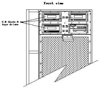
Figure 4-9 Possible Locations for 5.0 Gbyte 8 mm Tape Drives in the SPARCcenter 2000 System (Front View)
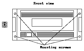
Figure 4-11 shows the three connectors that should have cables installed.
For the cables connected to the SCSI ID and power connectors, grasp each cable connector on both sides and firmly, but gently, pull the cable away from the connector at the rear of the tape drive.
For the cable connected to the SCSI connector, press out on the ejectors at the sides of the SCSI connector on the 5.0 Gbyte 8 mm tape drive to release the SCSI data cable from the tape drive (see Figure 4-12). Then grasp the cable connector by the attached strain relief tab and firmly, but gently, pull the cable away from the SCSI connector on the tape drive (see Figure 4-13).
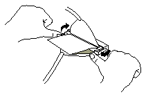
Figure 4-12 Releasing the Ejectors
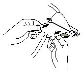
Figure 4-13 Disconnecting the SCSI Data Cable
Each mounting bracket is secured to the drive with two screws. Save the screws for the new drive.
Complete the procedures in the following sections to replace the assemblies and power on your SPARCcenter 2000 system.
Swing the top panel towards the cabinet and press against the right side of the panel until you hear it click into place.
Refer to the SPARCcenter 2000 Installation Manual (P/N 800-6975-xx) for instructions on powering on the cabinet.
You may have to enter a specific software command when booting the system so that the system will recognize the new drive; refer to the software handbook for your operating system for more information. For example, if your system is running on the Solaris 2.x operating system, you would enter the following command to boot up the system so that it would recognize the new drive:

Once you have completed the procedure for installing the 5.0 Gbyte 8 mm tape drive in the SPARCcenter 2000 system, you should have the following items remaining:
The remaining items will be used when you operate the 5.0 Gbyte 8 mm tape drive.
Follow these procedures if you want to verify that the 5.0 Gbyte 8 mm tape drive is installed in the SPARCcenter 2000 system correctly. Refer to the section entitled "When You Need Help with UNIX Commands" in the Preface of this manual if you need references to help with the commands or system administration procedures given below.
Once you have halted your system, you will see several system messages.

type "n" at the "" prompt and press <return:

This will bring you to the "ok" prompt.

You should see a list of drives similar to the following:
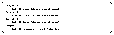
The "Target #" lines will tell you the SCSI addresses of the devices you have connected to your system.

Your screen will go blank for several seconds after you've entered this command, and then the system will reboot.
