
-----------------------------


Power Supply      page 8-1

LED               page 8-4

Audio Module      page 8-7

Internal Speaker  page 8-9

-----------------------------
1. Shut down and power off the system.
See Section 6.1, "Powering Off the System."
2. Remove the power cord from the system unit and from the wall outlet.
3. Remove the cover.
See Chapter 7, "Internal Access."
4. Disconnect the power supply connector from the system board, J1501.
See Figure 8-1.
5. Disconnect the power supply connector from the DC power harness.
See Figure 8-1.
6. Loosen the captive screw securing the power supply assembly to the
chassis.
See Figure 8-1.
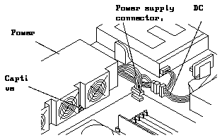
Figure 8-1
Disconnecting the Power Supply
7. Slide the power supply assembly toward the front of the chassis.
This unlocks the power supply from the power supply mounts. See
Figure 8-2.
8. Lift the power supply assembly out of the chassis and set it aside.
See Figure 8-2.
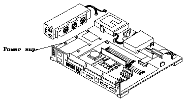
Figure 8-2
Removing the Power Supply from the Chassis
1. Align the power supply assembly in the chassis.
See Figure 8-2.
2. Slide the power supply assembly toward the rear of the chassis until it
locks in the power supply mounts.
3. Tighten the captive screw to secure the power supply to the chassis.
See Figure 8-1.
Caution -

Overtightening the captive screw may damage the chassis.
4. Connect the DC power connector to the system board connector, J1501.
See Figure 8-1. The connector can be connected one way only.
5. Connect the DC power connector to the DC power harness.
See Figure 8-1.
6. Replace the cover.
See Section 7.3, "Replacing the Cover."
7. Plug the power cord in to the system unit and the wall outlet.
8. Connect any expansion units you previously removed.
9. Power on the system.
See Section 6.2, "Restarting the System While Troubleshooting" or
Section 6.3, "Powering On the System."
1. Shut down and power off the system.
See Section 6.1, "Powering Off the System."
Note -
The power cord should remain connected to the computer system and
to the wall outlet or power strip.
2. Remove the cover and attach a wrist strap.
See Chapter 7, "Internal Access."
3. Remove the diskette drive from the system.
See Section 9.2, "Diskette Drive."
4. Disconnect the LED connector from the LED.
See Figure 8-3.
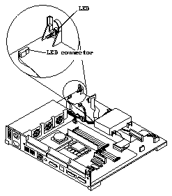
Figure 8-3
Removing or Installing the LED
5. Push the LED in using the tip of a Phillips screwdriver.
This frees the LED. See Figure 8-3.
6. Slide the LED out of its plastic enclosure.
1. Slide the LED into the LED cavity until it comes in contact with the
locating stop.
See Figure 8-3.
2. Connect the LED to the LED connector.
Insert the longer LED pin into the LED connector with the red wire. See
Figure 8-4.
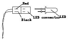
Figure 8-4
Connecting the LED to the LED Connector
3. Install the diskette drive.
See Section 9.2, "Diskette Drive."
4. Detach the wrist strap and replace the cover.
See Chapter 7, "Internal Access."
5. Connect any expansion units to the system you previously removed.
6. Power on the system.
See Chapter 6, "Power On and Off."
8.3.1
Removing the Audio Module - S10BSX Service Code
Note -
There is no audio module in the S10 service code.
1. Shut down and power off the system.
See Section 6.1, "Powering Off the System." The power cord should remain
connected to the computer system and to the wall outlet or power strip.
2. Remove the cover and attach a wrist strap.
See Chapter 7, "Internal Access."
3. Remove all MBus modules.
See Section 11.1, "MBus Module."
4. Remove the screw from the audio module. Lift up both edges of the
audio module.
See Figure 8-5.
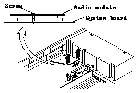
Figure 8-5
Removing the Audio Module
5. Place the audio module on an antistatic surface.
8.3.2
Installing the Audio Module - S10BSX Service Code
Note -
There is no audio module on the S10 service code.
1. From the side of the chassis, align the connectors.
2. Push down on both sides of the audio module above the connectors until
the connectors are fully engaged Replace the screw.
See Figure 8-6.
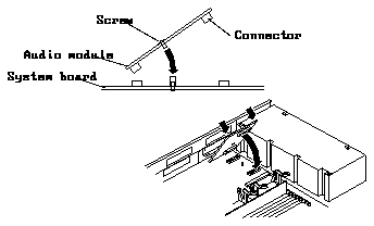
Figure 8-6
Installing the Audio Module
3. Replace the MBus modules.
See Section 11.1, "MBus Module."
4. Detach the wrist strap and replace the cover.
See Chapter 7, "Internal Access."
5. Power on the system.
See Chapter 6, "Power On and Off."
8.4.1
Removing the Internal Speaker - S10BSX Service Code
Note -
There is no internal speaker in the S10 service code.
1. Disconnect the speaker cable from the system board.
See Figure 8-7.
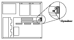
Figure 8-7
Disconnecting the Speaker Cable
2. Remove the screw from the speaker.
See Figure 8-8. The bracket will remain on the system board.
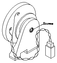
Figure 8-8
Removing the Speaker
3. Set the speaker aside.
8.4.2
Installing the Internal Speaker - S10BSX Service Code
Note -
There is no internal speaker in the S10 service code.
1. Remove the screw from the speaker bracket.
See Figure 8-8.
2. Install the speaker in the bracket already on the system board.
3. Connect the speaker cable to the system board.


