2 Installing the Drive in a SPARCcenter 2000 System


Make sure you have read the Preface for the safety precautions and Chapter 1 for pre-installation procedures and requirements before proceeding with this chapter.

2.1 Selecting a Drive Location

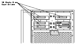
There are four locations for the 10 Gbyte 8 mm tape drive in the SPARCcenter 2000 system. See Table 2-1 and Figure 2-1.

    Table 2-1 Half-height Drive Locations (SPARCcenter 2000 System)

------------------------------------------
Drive Bay Location Number of Drives ------------------------------------------
                    
Upper Left          1 half-height drive1
                    
Upper Right         1 half-height drive1
                    
Lower Left          2 half-height drives

------------------------------------------
1Install the drive in the lower half of the bay; install a half-height
cover plate on the top half of the bay.

Each drive has its own ID select switch.

    Figure 2-1 10 Gbyte 8 mm Tape Drive Locations (SPARCcenter 2000 System)

2.2 Preparing the System

Complete the procedures in the following sections to prepare your system for installing or replacing a 10 Gbyte 8 mm tape drive.

2.2.1 Powering Off the System

    Power off the SPARCcenter 2000 system.

    Refer to the SPARCcenter 2000 Installation Manual (P/N 800-6975-xx) for instructions on safely powering off the cabinet.

2.2.2 Opening the Front Panel

    1. Pull on the right side of the top front panel on the SPARCcenter 2000 system to open the panel. See Figure 2-2.

    Figure 2-2 Opening the Top Panel (SPARCcenter 2000 System)

    2. If you are installing a drive in an empty bay, go to Section 2.4, "Installing a 10 Gbyte 8 mm Tape Drive," on page 2-5. If you are replacing an existing drive, continue to Section 2.3, "Removing an Existing Tape Drive," on page 2-4.

2.3 Removing an Existing Tape Drive

    1. Locate the drive you want to remove.
    2. If you are removing a half-height drive, remove the cover plate from the top half of the drive bay.

    Use the 9 mm hex-head socket to unscrew the two mounting screws.

    3. Remove the screws that secure the mounting bracket and drive to the front of the cabinet.

    Use the 9 mm hex-head socket. Full-height drives have four mounting screws; half-height drives have two mounting screws. See Figure 2-3.

    Figure 2-3 Removing a Half-height Drive (SPARCcenter 2000 System)

    4. Slide the drive out of the cabinet until the cables are exposed.
    5. Unplug the power cable, the SCSI ID cable, and the SCSI data cable from the rear of the drive.

    Firmly, but gently, pull the cable away from the connector at the rear of the tape drive. (For the power and SCSI ID cables, grasp each cable connector on both sides; for the SCSI data cable, use the strain relief tab.)

    6. Remove the tape drive from the bay.
    7. If you are installing a new 10 Gbyte 8 mm tape drive in the bay, proceed to Section 2.4, "Installing a 10 Gbyte 8 mm Tape Drive."
    8. If you are not installing a new tape drive in the empty drive bay:
      a. Install a cover plate on the bay.
      b. Proceed to Section 2.5, "Reassembling the System," on page 2-8.

2.4 Installing a 10 Gbyte 8 mm Tape Drive

Note - Make sure you have attached the mounting brackets to the tape drive, as described in Chapter 1, "Preparing for Installation."

    1. If there is a cover plate on the selected drive bay, remove the plate.
    See Figure 2-4.

    Use the 9 mm hex-head socket to remove the screws that secure the plate
    to the cabinet. (Full-height cover plates have four mounting screws; half- height cover plates have two.)

    2. Locate the SCSI ID (address) cable for the drive.

    One end of this cable is plugged into the device select switch for the drive bay. Note that the lower left drive bay has two device select switches.

    Figure 2-4 Device Select Switches and Cover Plate

    3. Plug the following cables into the rear of the new tape drive:

    Pin 1 of the address cable connector must plug into pin 1 of the SCSI ID connector on the drive.

    See Figure 1-4 for connector locations on the drive.

    4. Tuck the cables in behind the tape drive, and slide the drive into the bay. See Figure 2-5.

    Figure 2-5 Inserting the Drive into the Cabinet

    5. Secure the tape drive to the cabinet. See Figure 2-5.

    Use the 9 mm hex-head socket to install the two screws at the front of the mounting brackets.

    6. Install a half-height cover plate over the top half of the bay in which you just installed the tape drive. See Figure 2-4.
    7. Determine the SCSI address for the installed tape drive.

    The SCSI address depends on the SPARCcenter 2000 system configuration and the location of the drive.

    For example, your SPARCcenter 2000 system has both a CD-ROM drive and a 1/4-inch tape drive in the lower right bay (ID 6 and ID 5). See Figure 2-6. If all other drive bays are empty, you can:

Note - If the SPARCcenter 2000 system has more than one 1/4-inch tape drive, however, the ID numbers for all 1/4-inch tape drives must be higher than the ID numbers for any 8 mm or 4 mm tape drives.

    Figure 2-6 SCSI Addresses for CD-ROM and 1/2-Inch Tape Drive

    8. Use the drive bay's device select switch to set the SCSI address for the installed drive.

    Press the buttons marked "+" or "-" until you reach the correct address.

2.5 Reassembling the System

    1. Swing the top panel towards the cabinet and press against the right side of the panel until you hear it click into place.
    2. Power on the system.

    Refer to the SPARCcenter 2000 Installation Manual (P/N 800-6975-xx) for instructions.

2.6 Verifying Connection (Optional)

    To make sure that your system recognizes the newly-installed tape drive, use the procedures in Appendix A, "Probing for SCSI Devices."