4 Installing the Drive in a Multi-Tape Backup Tray


Make sure you have read the Preface for the safety precautions and Chapter 1 for pre-installation procedures and requirements before proceeding with this chapter.

4.1 Selecting a Drive Location

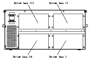
The 10 Gbyte 8 mm tape drive can be installed in any of the four bays of the Multi-Tape Backup Tray.

Tape drives must be installed in the drive bays in the following order:

See Figure 4-1 for the location of each drive bay. The drive bays are also labelled on the tray.

    Figure 4-1 Drive Bays in the Multi-Tape Backup Tray

4.2 Preparing the System

Complete the procedures in the following sections to prepare your system for installing the 10 Gbyte 8 mm tape drive.

4.2.1 Powering Off the System

    1. Power off the system cabinet and the 56-Inch Data Center Expansion Cabinet before proceeding with the following sections.

    Refer to the installation manual you received with your system for instructions:

4.2.2 Extending the Anti-Tilt Bar

Extend the anti-tilt bar from the cabinet bottom by grasping it underneath the front edge and pulling it out to its fully-extended position. See Figure 4-2.

    Figure 4-2 Anti-Tilt Bar and Top Front Panel

4.2.3 Removing the Panels

Removing the Top Front Panel
    Pull on both sides of the top front panel of the 56-Inch Data Center Expansion Cabinet, to remove the panel. See Figure 4-2.
Removing the Vented Rear Panel
    1. Face the rear of the cabinet and use a Phillips screwdriver to unscrew the two screws at the top of the vented rear panel. See Figure 4-3.

    Figure 4-3 Removing the Vented Rear Panel

    2. Pull the top of the vented rear panel away from the cabinet.
    3. Lift the vented rear panel until the bottom is clear and lift the panel away.

4.2.4 Preparing the Tray

Note - If you are installing a 10 Gbyte 8 mm tape drive in a Multi-Tape Backup Tray that is not yet installed in the cabinet, go to Step 5.

    1. Face the rear of the cabinet and disconnect the power cord from rear of the Multi-Tape Backup Tray. See Figure 4-4.

    Figure 4-4 Multi-Tape Backup Tray Power Receptacle and Ports

    2. Disconnect the SCSI data cable from the IN port at the rear of the tray.
    See Figure 4-4.

    Do not remove the terminator from the OUT port.

    3. Face the front of the cabinet and remove the four screws that secure the tray side brackets to the cabinet. See Figure 4-5.

    Figure 4-5 Tray Side Brackets and Top Cover Screws

    4. Fully extend the tray until the slide rail buttons click.
    5. Use the flat-head screwdriver to loosen the ten top cover captive screws. See Figure 4-5.

    There are three screws on each side and two each on the front and back of the tray.

    6. Remove the cover from the tray.
    7. Attach new side brackets to the tray.

    Use the side brackets that were shipped with your tape drive.

      a. Use the 7 mm hex-head socket to remove the two hex-head nuts that secure the side brackets to each side of the tray. See Figure 4-5.
      b. Get the side brackets from the shipping kit.
      c. Position each side bracket with the flat portion facing the rear of the tray, as shown in Figure 4-6.

    Figure 4-6 Side Brackets on a 56-Inch Expansion Cabinet

      d. Use the 7 mm hex-head socket and the M4 hex-head nuts to secure the two side brackets to the sides of the tray.
    8. If you are replacing an existing tape drive, proceed to Section 4.3, "Removing an Existing Tape Drive." If you are installing a new 10 Gbyte 8 mm tape drive, proceed to Section 4.4, "Installing a 10 Gbyte 8 mm Tape Drive," on page 4-9.

4.3 Removing an Existing Tape Drive

    1. Locate the drive you want to remove.
    2. Reach inside the tray from the top and unplug the power cable, the SCSI ID cable, and the SCSI data cable from the rear of the drive.

    Firmly, but gently, pull the cable away from the connector at the rear of the tape drive. (For the power and SCSI ID cables, grasp each cable connector on both sides; for the SCSI data cable, use the strain relief tab.)

    3. If you are removing a half-height tape drive, remove the half-height cover plate from the top half of the drive bay.

    Use the 9 mm hex-head socket to unscrew the two mounting screws.

    4. Remove the screws that secure the mounting brackets and drive to the front of the tray. Figure 4-7 shows the screws for a half-height drive.

    Use the 9 mm hex-head socket.

    Figure 4-7 Mounting Bracket Screws for Half-height Tape Drive

    5. Slide the drive out of the tray.
    6. If you are installing a new 10 Gbyte 8 mm tape drive in the tray, proceed to Section 4.4, "Installing a 10 Gbyte 8 mm Tape Drive."
    7. If you are not installing a new tape drive in the tray:
      a. Install two half-height cover plates (or one full-height cover plate) over the empty drive bay.
      b. Proceed to Section 4.5, "Securing the Tray," on page 4-14.

4.4 Installing a 10 Gbyte 8 mm Tape Drive

Note - Make sure you have attached the mounting brackets to the tape drive, as described in Chapter 1, "Preparing for Installation."

    1. If there is a cover plate on the selected drive bay:
      a. Remove the plate.

      Use the 9 mm hex-head socket to remove the screws that secure the plate to the tray.

      b. Secure the plate to the top of the fan assembly using two 9 mm hex-head screws.

      If there is a cover plate secured to the top of the fan assembly, put the cover plate you just removed in a safe place.

    2. Slide the tape drive into the bay until the mounting brackets rest flush against the front of the tray.
    3. Install the two screws that secure the mounting brackets and drive to the tray. See Figure 4-7.

    Use the 9 mm hex-head socket.

    4. Reach inside the tray from the top, and connect the DC harness cable to the power connector on the drive.

    Table 4-1 gives the correct DC harness connections for each 10 Gbyte 8 mm tape drive in the Multi-Tape Backup Tray, and Figure 4-8 shows how the DC harness cables should be routed in the tray.

    Table 4-1 DC Harness Cable Connections (Multi-Tape Backup Tray)

------------------------------------------
Tape Drive Location DC Harness Connector ------------------------------------------
                     
I                    P7
                     
II                   P8
                     
III                  P5
                     
IV                   P6

------------------------------------------

    Figure 4-8 Connecting the DC Harness Cable

    5. Connect the SCSI data cable to the SCSI connector on the drive.

    Table 4-2 gives the correct SCSI connections for each 10 Gbyte 8 mm tape drive in the Multi-Tape Backup Tray, and Figure 4-9 shows how the SCSI data cables should be routed in the tray. The connector is keyed so that you cannot install the cable incorrectly.

    Table 4-2 SCSI Data Cable Connections (Multi-Tape Backup Tray)

-----------------------------------------
Tape Drive Location SCSI Data Connector -----------------------------------------
                     
I                    P2
                     
II                   P3
                     
III                  P4
                     
IV                   P5

-----------------------------------------

    Figure 4-9 Connecting the SCSI Data Cable

    6. Connect the address cable to the SCSI ID connector on the drive.

    Table 4-3 gives the correct SCSI ID connections for each 10 Gbyte 8 mm tape drive in the Multi-Tape Backup Tray, and Figure 4-10 shows how the address cables should be routed in the tray.

    Table 4-3 Address Cable Connections (Multi-Tape Backup Tray)

---------------------------------------
Tape Drive Location Address Connector ---------------------------------------
                     
I (J1)               P1
                     
II (J2)              P2
                     
III (J3)             P3
                     
IV (J4)              P4

---------------------------------------

    Figure 4-10 Connecting the Address Cable

Position the address cable so that the black wire is located at the lower right corner of the SCSI ID connector.

    7. Determine the SCSI address for the 10 Gbyte 8 mm tape drive.

    The SCSI addresses for the 10 Gbyte 8 mm tape drives in the Multi-Tape Backup Tray depend on the location of the tape drives in the tray. Table 4-4 shows the SCSI addresses for tape drives in a tray installed in a 56-Inch Data Center Expansion Cabinet.

    Table 4-4 SCSI Addresses for Tape Drives (Multi-Tape Backup Tray)

------------------------
Drive Bay SCSI Address ------------------------
           
I          5
           
II         3
           
III        2
           
IV         4

------------------------
    8. Set the SCSI address for the tape drive.

    Figure 4-11 shows the four device select switches at the front of the Multi- Tape Backup Tray. Select the appropriate switch for the new drive, and press the buttons marked "+" or "-" until you see the correct address in the window.

    Figure 4-11 Device Select Switches (Multi-Tape Backup Tray)

    9. Install a half-height cover plate over the top half of the bay in which you installed the new drive.

4.5 Securing the Tray

    1. Install the top cover after you have installed or removed a tape drive.

    Use the flat-head screwdriver to tighten the ten top cover captive screws.

    2. Press the button in the center rail and push the tray completely into the cabinet.
    3. Use the Phillips screwdriver to install the four 10-32 screws in the side brackets.
    4. Connect the power cable to the power connector and the SCSI data cable to the IN port on the rear of the Multi-Tape Backup Tray. See Figure 4-4.

    The OUT port should have a terminator already installed.

4.6 Reassembling the System

The following sections describe how to replace the panels on your 56-Inch Data Center Expansion Cabinet.

4.6.1 Installing the Vented Rear Panel

    1. Place the bottom of the vented rear panel in the groove on the top of the kick panel.
    2. Swing the top of the vented rear panel towards the cabinet until the top of the panel is touching the cabinet.
    3. Use a Phillips screwdriver to install the two screws at the top of the vented rear panel.

4.6.2 Installing the Top Front Panel

    1. Place the vented front panel in the proper position and press on both sides of the panel until it engages.
    2. Retract the anti-tilt bar at the bottom of the cabinet.

4.6.3 Powering On the System

    Power on the system.

    Refer to the installation manual you received with your system for instructions on safely powering on the cabinet.

4.7 Verifying Connection (Optional)

To make sure your system recognizes the newly-installed tape drive, use the procedures in Appendix A, "Probing for SCSI Devices."