Opening or Removing the Panels
The AC power cord should remain attached between the system unit and an AC wall outlet. This connection provides the ground path necessary to protect internal system components from harmful static discharges.
Before opening the system unit, make sure that the system power switch is in the OFF (O) position. When the system power switch is in the OFF (O) position, and the AC power cord remains connected to a power outlet, hazardous AC voltage may still present in the main power supply, disk bay power supply and Uninterrupted Power Supply (if present). Do not attempt to service any of the power supplies under these conditions. Disconnect the AC power cord prior to handling any power supplies. When servicing any other system component besides the power supplies, be sure the AC power cord is connected; it poses no safety hazard.
You will have to open or remove certain panels to install or replace hardware in the Netra 150 server:
-
If you are installing or replacing a tape drive, go to "Opening the Upper Front Panel".
-
If you are installing or replacing a bay disk drive, go to "Opening the Lower Front Panel".
-
If you are installing or replacing an SBus card or a DSIMM, go to "Removing the Left Panels and Foam Piece 1".
Opening the Upper Front Panel
-
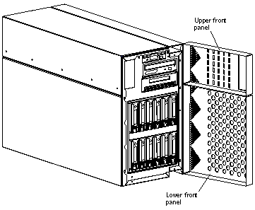
Grasp the handle on the left side of the upper front panel and pull sharply to open the panel (Figure 2-2).
Figure 2-2 Opening the Upper and Lower Front Panels
Opening the Lower Front Panel
-
Open the lock on the lower front panel.
-
Grasp the handle on the left side of the lower front panel and pull sharply to open the panel (Figure 2-2).
Removing the Left Panels and Foam Piece 1
-
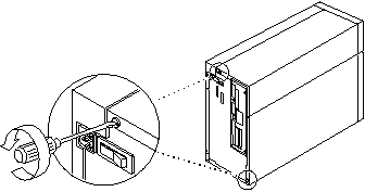
Loosen the two Phillips-head captive screws on the left outer panel at the rear of the Netra 150 server (Figure 2-3).
Figure 2-3 Locating the Captive Screws for the Left Outer Panel
-
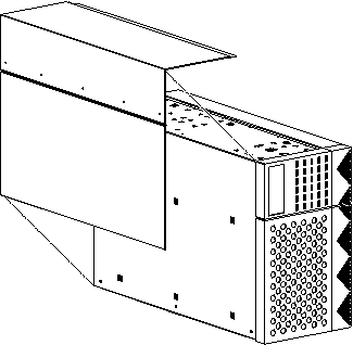
Slide the left outer panel toward the rear of the Netra 150 server until it stops, then tilt the panel out until it is clear of the chassis (Figure 2-4).
Figure 2-4 Removing the Left Outer Panel
-
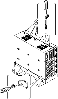
Use the Phillips #1 screwdriver to loosen the eight Phillips-head captive screws at the side and top of the left inner panel (Figure 2-5).
The screw at the top front portion of the panel does not attach to anything.
Figure 2-5 Removing the Left Inner Panel
-
Tilt the top of the left inner panel up until it is clear of the chassis and pull it away from the chassis.
-
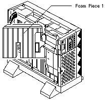
Pull the left side of Foam Piece 1 out of the chassis (Figure 2-6).
The right side of the foam piece stays in place.
Figure 2-6 Pulling the Left Side of Foam Piece 1
-
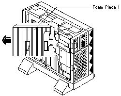
Pull Foam Piece 1 away from the Netra 150 server (Figure 2-7).
Be careful that you do not disturb the surrounding assemblies and cables.
Figure 2-7 Removing Foam Piece 1
- © 2010, Oracle Corporation and/or its affiliates
