| C H A P T E R 4 |
|
Sun XVR-500 Graphics Accelerator Frame Locking |
This chapter describes Sun XVR-500 graphics accelerator frame locking.
The frame lock synchronization feature enables vertical retracing to occur simultaneously on each Sun XVR-500 graphics accelerator subsystem. The frame lock cable assembly is used to daisy-chain two or more Sun XVR-500 graphics accelerator subsystems. Vertical retrace synchronization eliminates flicker between multiscreen displays.
Frame locking is often necessary when running in stereo in a multihead environment. All the displays can be synchronized so that the left and right views can be seen correctly through one set of LCD stereo glasses.
When frame buffers are frame locked, you should make sure they are all running at the same video resolution and vertical retrace rate (see fbconfig -help for details). See Configuring Sun XVR-500 Graphics Accelerators for Frame Locking.
To use the frame lock features, the frame lock cable assembly is required. See Frame Lock Cable Assembly for installation.
To order the frame lock cable assembly, call Sun Telesales at 1-800-786-0404 and request spare part number 530-2754. You can also order the frame lock cable assembly through the Sun store (http://store.sun.com) by ordering this part number under spare parts.
By default, two channels are not frame locked.
TABLE 4-1 lists the supported systems for frame locking and lists the supported number of devices for each system.
1. Designate a Sun XVR-500 graphics accelerator as master for the graphics boards to be in frame lock.
You can use the Sun XVR-500 graphics accelerator that serves as the boot/console head for that system.
Refer to the boot -r man page for device location and device numbering information for how devices are numbered based on their physical location. For frame lock, you may select any device (that is, ifb0, ifb1, ifb2,...and so on) to be the master Sun XVR-500 graphics accelerator device.
2. Make sure that each Sun XVR-500 graphics accelerator installed has the same monitor resolution as the one in master mode.
a. Check the resolution of an Sun XVR-500 graphics accelerator by using the fbconfig command. For example:
% fbconfig -dev /dev/fbs/ifb0 -prconf |
You must repeat this command for each Sun XVR-500 graphics accelerator in the system or systems.
The fbconfig command displays the current monitor resolution setting. It also displays additional information such as whether the Sun XVR-500 graphics accelerator is a master or slave.
b. (Optional) Change the resolution of a Sun XVR-500 graphics accelerator using the fbconfig command.
If the resolution on each Sun XVR-500 graphics accelerator is not the same, you must change it to match the Sun XVR-500 graphics accelerator in master mode. For example:
% fbconfig -dev /dev/fbs/ifb1 -res 1280x1024x76 now nocheck |
If the resolution on each Sun XVR-500 graphics accelerator is not the same, you must change it to match the Sun XVR-500 graphics accelerator in master mode.
3. Connect the frame lock cable to each Sun XVR-500 graphics accelerator.
Make sure to first connect the top of the frame lock cable assembly to the master Sun XVR-500 graphics accelerator.
See the section Frame Lock Cable Assembly.
4. From the master Sun XVR-500 graphics accelerator display window, configure the other Sun XVR-500 graphics accelerators in slave mode.
Use the fbconfig command. For example:
% fbconfig -dev /dev/fbs/ifb1 -slave enable |
You must configure each board separately (that is, for ifb1, ifb2, ifb3, and so on).
Your system is now ready for frame locking.
To reconfigure your Sun XVR-500 graphics accelerator from slave mode back to master mode, use the fbconfig command. For example:
% fbconfig -dev /dev/fbs/ifb1 -slave disable |
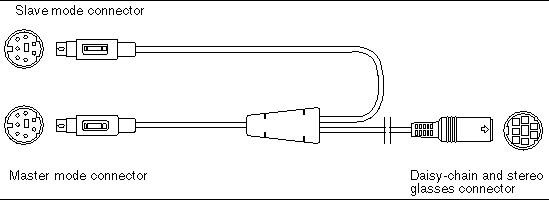
The frame lock cable assembly, FIGURE 4-1, is a Y-shaped cable assembly with three connectors for daisy-chaining multiple Sun XVR-500 graphics accelerator within a computer system. (See Appendix A, Stereo Output Port, for the stereo connector pinout signals.)
 [ D ]
[ D ]
|
Note - There can only be one master Sun XVR-500 graphics accelerator device. You must configure all other Sun XVR-500 graphics accelerator devices as slaves. See the section Configuring Sun XVR-500 Graphics Accelerators for Frame Locking. |
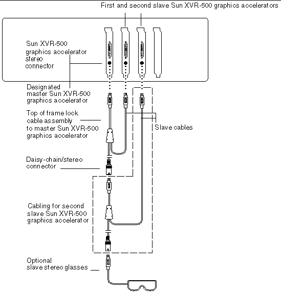
1. Locate the master Sun XVR-500 graphics accelerator I/O backplate on the rear of your system and connect the top of the frame lock cable assembly stereo connector.
2. Connect the slave cable connector to a slave Sun XVR-500 graphics accelerator stereo connector.
3. Connect a second slave Sun XVR-500 graphics accelerator, if applicable, or stereo glasses to the daisy-chain/stereo connector (FIGURE 4-2).
 [ D ]
[ D ]
Copyright © 2002, Sun Microsystems, Inc. All rights reserved.