| C H A P T E R 4 |
|
Battery FRUs |
This chapter provides instructions for removing and installing batteries and battery modules. The FC arrays have an independent battery module located above each I/O module. The SCSI arrays contain a battery on each controller module.
The battery dating information is the same for all batteries.
Topics covered in this chapter are:
Your lithium ion battery should be changed every two years if the unit is continuously operated at 25 degrees C. If the unit is continuously operated at 35 degrees C or higher, it should be changed every year. The shelf life of your battery is three years.
In the event of a power failure, the battery maintains power to the cache for 72 hours. When power is restored, the data in cache is dumped to disk.
The battery LED (on the far right side of the controller module) is an amber LED if the battery is bad or missing. The LED blinks green if the battery is charging and is solid green when the battery is fully charged.
The initial firmware screen displays the battery status at the top of the initial screen where BAT: status displays somewhere in the range from BAD to ----- (charging), or +++++ (fully charged).
For maximum life, lithium ion batteries are not recharged until the charge level is very low, indicated by a status of -----. Automatic recharging at this point takes very little time.
A battery module whose status shows one or more + signs can support cache memory for 72 hours. As long as one or more + signs are displayed, your battery is performing correctly.
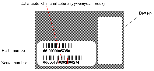
The battery modules display a serial number/part number label, whose placement on the battery is shown in FIGURE 4-1 and FIGURE 4-2.
Below the top bar code is a seven-digit code that indicates the place of manufacture, followed by a dash (-), followed by a four-digit code that indicates the date of manufacture, followed by a six-digit supplier-assigned serial number.
In FIGURE 4-1, the example date of battery manufacture is indicated by "0240," where "02" is the year of manufacture and "40" is the week of manufacture. If a battery does not have a serial number/part number label, the manufacture date for the battery is August 2002.
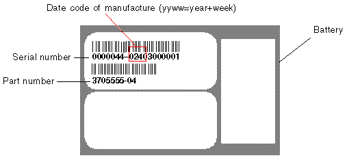
In FIGURE 4-1, the number below the bottom bar code is the part number (for example, 3705555-04).
This section explains how to remove an existing battery and install a new battery. The following procedures are guidelines for replacing batteries in SCSI and FC arrays.
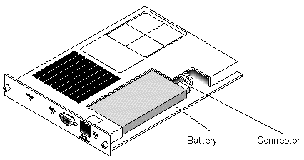
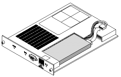
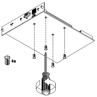
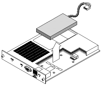
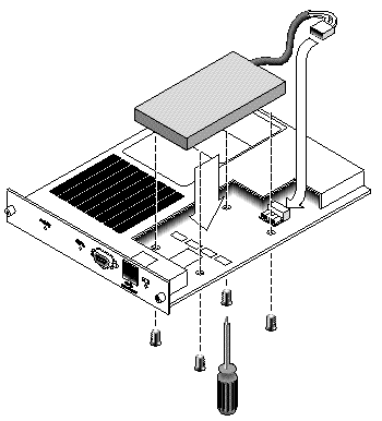
To replace a SCSI array battery, perform the following steps (refer to FIGURE 4-3 through FIGURE 4-7).
1. Turn the thumbscrews on the left and right sides of the controller module that contains the battery counterclockwise until the thumbscrews are disengaged from the chassis.
2. Hold the thumbscrews and pull out the battery module to check the battery date.
3. To replace the battery, pull out the controller module completely.
4. Disconnect the battery connector from the controller module.
5. With a screwdriver, remove the battery screws to release the battery from the battery module.
7. Insert the new battery, and attach the battery connector to the controller module.
8. With a screwdriver, attach the battery to the controller with the screws that you removed in Step 5.
9. Reinsert the controller module into the array, and tighten the thumbscrews firmly to secure the module.
To replace a FC array battery, perform the following steps.
1. Turn the thumbscrews on the left and right sides of a battery module for the FC array counterclockwise until the thumbscrews are disengaged from the chassis.
2. Hold the thumbscrews and pull out the battery module to check the battery date.
3. To replace the battery, pull out the battery module completely and disconnect the battery connector from the battery module.
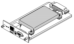
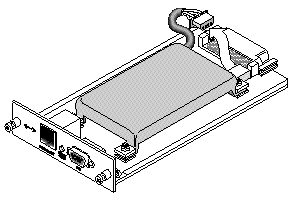
4. Remove the battery screws on the underside of the module to release the battery from the battery module, similar to the screw removal shown in FIGURE 4-5.
6. Insert the new battery and attach the battery connector to the battery module.
7. With a screwdriver, attach the battery to the controller with the screws that you removed in Step 4.
8. Reinsert the battery module into the array, and tighten the module thumbscrews firmly to secure the module.
9. Set the in-service dates for the new FC battery replacement with the CLI or SSCS program. For details, refer to FC Battery Status and In-Service Date Procedures.
The CLI and SSCS programs offer the following features for FC battery modules:
This command sets the in-service date for battery FRU replacements and displays the status of the battery modules.
|
Note - If the battery type is an early board module, then battery expiration monitoring is not supported. In this case, a message displays that says, "battery board type is not supported." |
The following example shows one good battery one and one battery that is set to expire within the next week:
Sun StorEdge Configuration Service monitors the usable life of the FC battery and displays its status in the Battery Information window. The program calculates the battery expiration date using the battery type, manufacture date, and in-service date, which have been programmed at the factory.
|
Note - For an FC battery FRU, you need to verify the in-service date so that Sun StorEdge Configuration Service can set it as explained in Verifying the In-Service Date When Replacing a Battery in SSCS. |
The enclosure icon on the main window displays a degraded (yellow) status 21 days before the battery is going to expire. The enclosure icon also displays a warning (yellow) status if the in-service date has not been set for a battery FRU. A critical (red) status is displayed when a battery has expired.
To view the battery status, choose View  View Enclosure or double-click the enclosure. The View Enclosure window is displayed, showing the battery status in the Summary box.
To view battery information, including type, status, manufacture date, in-service date, and expiration date, click Battery. The Battery Information window is displayed.
When Sun StorEdge Configuration Service detects a battery FRU, the enclosure icon displays a degraded (yellow) status symbol as shown in the following example.
1. Double-click the enclosure icon.
Sun StorEdge Configuration Service calculates the battery expiration date using the in-service date (date that the battery is put into service), which is based on the host clock. The program prompts you to verify the date by displaying the following message:
2. If the host clock is correct, click Yes.
The following confirmation message is displayed. Click OK.
Sun StorEdge Configuration Service sets the in-service date and displays the date in the In-Service Date field in the Battery Information window.
3. If the host clock is incorrect, click No and reset the clock so that Sun StorEdge Configuration Service can prompt you to verify it again and set the in-service date.

|
Caution - If you do not reset and verify the in-service date, Sun StorEdge Configuration Service cannot accurately calculate the battery expiration date. |
Copyright © 2004, Sun Microsystems, Inc. All rights reserved.