| C H A P T E R 2 |
|
Accessing the Controller Firmware |
The RAID controller firmware can be configured using a VT100-compatible terminal or a workstation running a terminal emulation program. Topics covered in this chapter include:
The RAID controller can be configured by means of a Solaris workstation running a VT100 terminal emulation program, or by a Microsoft Windows terminal emulation program such as HyperTerminal.
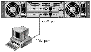
1. Use a serial cable to connect the COM port of the RAID array to an unused serial port on your server.
A DB-9-to-DB-25 serial cable adapter is provided to connect the serial cable to DB-25 serial ports on workstations.
Make sure that a null modem cable can be attached to the host serial port. The null modem cable has serial signals swapped for connecting to a standard serial interface.

It can take two or three minutes for both controllers to be initialized before communication is possible over the connection.
3. Set these serial port parameters on the workstation:
You can specify the baud rate of 38,400 when you type the tip command.
1. Connect the RAID array COM port to a serial port of a Solaris workstation (see FIGURE 2-1).
Use the tip command to access the array locally.
where n is the COM port identifier. For instance, if you have connected the array to the COM port identified as ttyb, use this command:
2. Refresh your screen by holding down the Control key on your keyboard (this is abbreviated Ctrl on some keyboards) and pressing the letter L key on your keyboard.
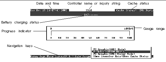
You see the initial controller screen (FIGURE 2-2) when you first access the RAID controller firmware.

The initial screen is displayed when the RAID controller is powered on. Use the up and down arrow keys to choose the VT100 terminal emulation mode, and then press Return to enter the Main Menu.
The progress indicator is displayed when necessary to indicate the percentage of completion of a particular task or event. Sometimes the event is represented by a descriptive title, such as "Drive Copying:"
Event messages showing full descriptive titles for the progress indicator include:
For other events, the progress indicator merely shows a two-letter code in front of the percentage completed. These codes and their meanings are shown in the following table:
The firmware screens described in this document, along with the steps you follow, are the same regardless of whether you have connected to the controller through an IP address or through a serial port connection.
|
Note - The firmware functionality is similar for both Fibre Channel and SCSI arrays, but the contents of some informational screens vary between platforms. |
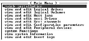
Once you have chosen the VT 100 Terminal Emulation display mode, the Main Menu is displayed.

|
Note - Since Fibre Channel and SCSI arrays share the same controller firmware, most menu options are the same. Parameter values might vary according to the product. |
Use the following keys to navigate within the Main Menu and all its submenus.
|
To return to the previous menu without performing the selected menu option |
|
|
Press a letter as a keyboard shortcut for commands which have a boldface capital letter |
The firmware procedures use the term "Choose" as a shortcut description. Quotation marks are used to indicate a specific menu option or a series of menu options.

|
Caution - Do not use this command unless directed by Technical Support. |
Firmware upgrades are performed by downloading firmware patches. For firmware upgrade procedures and any prerequisite upgrades, refer to the release notes for your array.
Copyright © 2004, Sun Microsystems, Inc. All rights reserved.