| C H A P T E R 3 |
|
Viewing and Editing Logical Drives |
This chapter explains how to view and edit logical drives. Topics covered include:
Use the "view and edit Logical drives" command to combine physical SCSI drives into a logical drive.
For additional commands, highlight the first line or the desired logical drive (LG), and press Return. The following menu is displayed:
Under this menu command, you can create multiple logical drives. Once logical drives are created, you can manipulate them by choosing a desired logical drive.
To create logical drives, you must map the logical drives to a host channel with the "view and edit Host luns" command. If this step is skipped, the logical drives will not be visible to the host.
A logical drive is a set of drives grouped together to operate under a particular RAID level. Each RAID array is capable of supporting as many as eight logical drives.
A drive can be assigned as the local spare drive to one specified logical drive, or as a global spare drive that is available to all logical drives on the RAID array.
Spares can be part of an automatic array rebuild.
|
Note - A spare is not available for logical drives with no data redundancy (RAID 0). |
The logical drives can have the same or different RAID levels.
For a 12-drive array, the RAID array is preconfigured as:
For a 5-drive array, the RAID array is preconfigured as:
For more information about spares and RAID levels, refer to RAID Levels and Local and Global Spare Drives.
|
Note - To reassign drives and add additional local or global spares on your preconfigured array, you must first unmap and then delete the existing logical drives, and then create new logical drives. |
To check and configure logical drives, choose "view and edit Logical drives" from the Main Menu.
The status of all logical drives is displayed in a table.
The RAID array is already configured with one or two RAID 5 logical drives and one or two global spares. Each logical drive consists of a single partition by default.
If you prefer a different configuration, use the procedure described in this section to modify the RAID level or to add more logical drives. In this procedure, you configure a logical drive to contain one or more hard drives based on the desired RAID level, and partition the logical drive into additional partitions.
For redundancy across separate channels, you can also create a logical drive containing drives distributed over separate channels. You can then partition the logical unit into one or several partitions.
In a RAID 1 or RAID 1+0 configuration the order in which you select the physical disks for a logical drive determines the channels to which they are assigned. If you wish drives to be mirrored over two channels, select them in the appropriate order. For example:
1. The first drive you select is assigned to channel 2, ID 0.
2. The second drive you select is assigned to channel 0, ID 0.
3. The third drive you select is assigned to channel 2, ID 1.
4. The fourth drive you select is assigned to channel 0, ID 1.
A logical drive consists of a group of SCSI drives. Each logical drive can be configured at a different RAID level.
A physical drive can be assigned as the local spare drive to a specified logical drive, or as a global spare drive that is available to all logical drives on the RAID array. Spare drives can be part of automatic array rebuild. Spare drives are not available for logical drives with no data redundancy (RAID 0).
|
Note - This procedure is applicable to both SCSI and FC arrays. The illustrations show FC examples. |
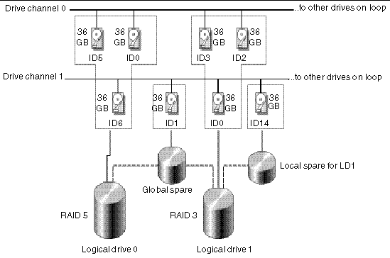
Before configuring disk drives into a logical drive, you must know the status of physical drives in your enclosure.
a. Choose "view and edit Scsi drives."
A table shows information about all the physical drives that are installed.
b. Use the arrow keys to scroll through the table. Check that all installed drives are listed here.
If a drive is installed but is not listed, it might be defective or might not be installed correctly. Refer to the Sun StorEdge 3000 Family FRU Installation Guide for 2U Arrays for information about scanning and replacing drives.
When the power is on, the controller scans all physical drives that are connected through the drive channels. If a physical drive was connected after the controller completed initialization, use the "Scan scsi drive" menu on the "view and edit scsi Drives" menu so the controller can recognize the newly added hard drive. Then you can configure the new drive as a member of a logical drive.

|
Caution - Scanning an existing drive removes its metadata references and its assignment to any logical drive. All data on that drive is lost. |
a. Choose "view and edit logical drive" from the Main Menu.
b. Select the first available unassigned logical group (LG) to proceed.
3. When prompted to "Create Logical Drive?" choose Yes to proceed.
A pull-down list of supported RAID levels is displayed.
4. Choose a RAID level for this logical drive.
For brief descriptions of RAID levels, refer to Default Logical Drives and RAID Levels. See Basic RAID Concepts for more detailed information about RAID levels.
5. Select your member drives from the list of available physical drives.
The drives can be tagged for inclusion by highlighting the drive and then pressing Return. An asterisk (*) is displayed on the tagged physical drives.
To deselect the drive, move the cursor bar back to the physical drive and press Return again. The "*" disappears.
|
Note - You must select at least the minimum number of drives required for the RAID level you've chosen. See RAID Levels for information about the minimum numbers of drives required for each RAID level. |
a. Use the up and down arrow keys and press Return to select more drives.
b. After all physical drives have been selected for the logical drive, press the Esc key to continue to the next option.
After member physical drives are selected, a menu of configuration options is displayed.
6. (Optional) Set Maximum Physical Drive Capacity and assign spares.
a. (Optional) Choose "Maximum Drive Capacity" from the menu.
|
Note - Changing the maximum drive capacity reduces the size of the logical drive and leaves some disk space unused. |
As a rule, a logical drive should be composed of physical drives with the same capacity. A logical drive can only use the capacity of each drive up to the maximum capacity of the smallest drive.
b. Replace the value in the Maximum Drive Capacity<MB> text area with the desired capacity value and press Return.
c. (Optional) Add a local spare drive from the list of unused physical drives.
|
Note - A global spare cannot be created while creating a logical drive. |
The local spare selected here automatically replaces any failed physical drive in this logical drive. The local spare is not available for any other logical drive.
|
Note - A logical drive created in RAID level 0, which has no data redundancy, does not support spare drive rebuilding. |
7. (Optional) Choose "Logical Drive Assignments" to assign this logical drive to the secondary controller.
By default, all logical drives are automatically assigned to the primary controller.
If you use two controllers for the redundant configuration, a logical drive can be assigned to either of the controllers to balance workload. Logical drive assignment can be changed any time later.

|
Caution - Do not assign logical drives to secondary controllers in single-controller arrays. Only the primary controller works in these arrays. |
a. Press the Esc key or No to exit from this window without changing the controller assignment.
b. Choose Yes, press Return to confirm, and then press the Esc key to continue when all the preferences have been set.
A confirmation box is displayed on the screen.
c. Verify all information in the box before choosing Yes to proceed.
A message indicates that the logical drive initialization has begun.
d. Press the Esc key to cancel the "Notification" prompt.
e. After the logical drive initialization is completed, use the Esc key to return to the Main Menu.
8. Choose "view and edit Logical drives" to view details of the created logical drive.
By default, logical drives are automatically assigned to the primary controller. If you assign half the drives to the secondary controller, the maximum speed and performance is somewhat improved due to the redistribution of the traffic.
To balance the workload between both controllers, you can distribute your logical drives between the primary controller (displayed as the Primary ID or PID) and the secondary controller (displayed as the Secondary ID or SID).
After a logical drive has been created, it can be assigned to the secondary controller. Then the host computer associated with the logical drive can be mapped to the secondary controller (see Mapping Logical Drive Partitions to Host LUNs).

|
Caution - Do not assign logical drives to secondary controllers in single-controller arrays. Only the primary controller works in these arrays. |
1. To change a logical drive controller assignment, choose "view and edit Logical drives" from the Main Menu.
2. Select the drive you want to reassign.
3. Choose "logical drive Assignments."
The reassignment is evident from the "view and edit Logical drives" screen.
A "P" in front of the LG number means that the logical drive is assigned to the primary controller. An "S" in front of the LG number means that the logical drive is assigned to a secondary controller.
For example, "S1" indicates that logical drive 1 assigned to the secondary controller.
4. Reassign the controller by choosing Yes.
You must reset the controller for the changes to take effect.
5. Press Esc to display the Main Menu.
6. From the Main Menu, choose "system Functions  Reset controller."
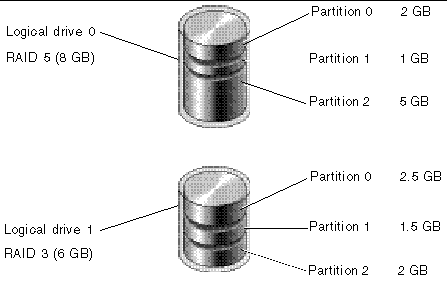
You can divide a logical drive into several partitions, or use the entire logical drive as a single partition. You can configure up to 32 partitions for each logical drive.
For guidelines on setting up 128 LUNs on SCSI arrays, refer to Mapping Logical Drive Partitions to Host LUNs.
For guidelines on setting up 1024 LUNs on Fibre Channel arrays, refer to Planning for 1024 LUNs on FC Arrays.

|
Caution - If you modify the size of a partition or logical drive, you lose all data on those drives. |
1. From the Main Menu, choose "view and edit Logical drives."
2. Select the logical drive you want to partition.
3. Choose "Partition logical drive."
The following message is displayed:
4. Choose Yes to confirm that you want to partition the logical drive and do not want to include it in a logical volume.
A list of the partitions for this logical drive is displayed. If the logical drive has not yet been partitioned, all the logical drive capacity is listed as "partition 0."
5. Select from the list of undefined partitions.
6. Type the desired size for the selected partition and press Return.
A warning prompt is displayed:

|
Caution - Make sure any data on this partition that you want to save has been backed up before you partition the logical drive. |
The remaining capacity of the logical drive is automatically allotted to the next partition. In the following figure, a partition size of 3000 MB was entered; the remaining storage of 27,000 MB is allocated to the partition below the partition created.
8. Repeat the preceding steps to partition the remaining capacity of your logical drive.
|
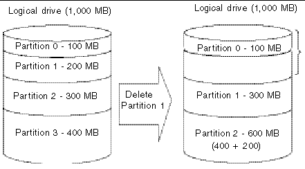
Note - When a partition on a logical drive or logical volume is deleted, the capacity of the deleted partition is added to the partition above the deleted partition. |
|
Note - When you modify a partition or logical drive size, you must reconfigure all host LUN mappings. All the host LUN mappings are removed with any change to partition capacity. See Mapping a Partition to a LUN. |
If you are using a Solaris host, you should use the "Auto configure" menu option from the format menu whenever you resize a logical drive.
For the Solaris operating environment to recognize a LUN, it must be labeled with the format command. Whenever you create or reconfigure a LUN, label it using the following procedure. For more information on the format command, see the format(1M) man page.
|
Note - This example applies to the Sun StorEdge 3310 SCSI array. Follow the same steps for Sun StorEdge 3510 FC arrays as well, using the appropriate drive type and label. |
1. On the data host, type format at the root prompt.
2. Specify the disk number when prompted.
In this example, the array is shown as disk number 2. It can be identified by the SUN-StorEdge3310-0325 label.
3. Type type to select a drive type.
4. Type 0 to choose the Auto configure menu option.
Select the Auto configure menu option regardless of which drive types are displayed by the type option. For further information on partitioning, see the Solaris format(1M) man page.
5. Type label and answer y when prompted to continue.
You can keep the default logical drive configuration, or create new logical drives and different RAID levels with the following procedure. To reconfigure the entire array with different logical drives and RAID levels, you must first delete the existing logical drives and reconfigure the array prior to storing data on the array.

|
Caution - This operation erases all data on the logical drive. Therefore, if any data exists on the logical drive, copy it to another location before deleting the current logical drive. |
|
Note - You can only delete a logical drive if it has first been unmapped. |
1. From the Main Menu, choose "view and edit Logical drives."
2. Select the logical drive to be deleted.
3. Choose "Delete logical drive."
A warning notice is displayed.
4. If it is safe to delete the logical drive, choose Yes.
When you delete a partition on a logical drive, all of the capacity of the deleted partition is added to the remaining partition with the highest partition number. If a logical drive contains partitions 0 through 3 and you delete partition 3, for example, all of the capacity of partition 3 is added to partition 2.
1. Choose "view and edit Logical drives" from the Main Menu.
2. Select the logical drive that has a partition you want to delete.
3. Choose "Partition logical drive."
Partitions of the logical drive are displayed in a table.
4. Select the partition you want to delete.
5. Type "0" in the Partition Size (MB) text area to delete this partition.
A warning prompt is displayed:
As illustrated in FIGURE 3-3, the capacity of the deleted partition 1 (200 MB) is added into the last partition (now partition 2), which combines 400 MB and 200 MB for a total of 600 MB.

|
Caution - If a partition has been changed, you must reconfigure all host LUN mappings. All the host LUN mappings are removed with any partition change. |
You can assign a name to a logical drive after the logical drive is created. This logical drive name is used only in the RAID firmware administration and monitoring, and does not appear anywhere on the host. You can also edit this drive name.
1. Choose "view and edit Logical drives" from the Main Menu.
2. Select the logical drive that you want to name.
3. Choose "logical drive Name."
4. Type the name you want to give the logical drive in the "New Logical Drive Name" text area and press Return to save the name.
If no spare drive is available for logical drive rebuilding, replace the failed drive immediately with a new drive and initiate the rebuild process manually.
1. Choose "view and edit Logical drives" from the Main Menu.
2. Select the logical drive that has a failed member drive.
3. Choose "Rebuild logical drive."
4. When prompted to rebuild the logical drive, choose Yes.
The rebuilding progress is displayed on the screen.
When rebuilding has already started or the logical drive has been automatically rebuilt by a local spare drive or global spare drive, choose "Rebuild progress" to view the rebuilding progress.
|
Note - The rebuild function is displayed only when a logical drive (with RAID level 1, 3. or 5) has a failed drive member. RAID 0 configurations provide no data redundancy. |
RAID 3 and RAID 5 configurations support parity checking. If no verifying method is applied to data writes in these configurations, you can periodically use the "reGenerate parity" menu option to perform a parity check for RAID levels that support parity. In a RAID unit, data is striped across multiple member drives and this menu option can regenerate parity and report any discrepancy.
1. Choose "view and edit Logical drives" from the Main Menu.
2. Select the logical drive that you want to regenerate the parity for.
3. Choose "reGenerate parity  Execute Regenerate Logical Drive Parity."
4. When prompted to regenerate the parity, choose Yes.
A notification is displayed that parity regeneration has begun.
5. Press Esc to see a progress indicator.
|
Note - If a regenerating process is stopped by a drive failure, the process cannot restart until the logical drive rebuild has been completed. |
In normal operation, many regions of physical disks might not be accessed for long periods of time. The primary purpose of the parity checking operation in RAID 3 and RAID 5 configurations is to ensure that all sectors of the media can be successfully read and to provide alerts if a disk is starting to experience read or write errors.
If the result of a parity check indicates an inconsistency, it indicates that a data error exists either on one of the disk drives or on the parity drive. However, RAID algorithms such as RAID 5 that use XOR parity cannot determine if the error resides on a data disk or on the parity disk. Enabling the "Overwrite Inconsistent Parity" menu option causes the RAID controller to correct the data on the parity disk automatically whenever a parity check detects an inconsistency. In most cases it is important to correct the data on the parity disk as soon as an inconsistency is detected, in order to avoid the potential for data loss in the event of a drive failure.
However, some users prefer to check the integrity of their data before overwriting the parity disk. Disabling the "Overwrite Inconsistent Parity" menu option causes the controller to report any inconsistency found in a parity check without overwriting the parity disk. In this case you can check your data and determine if it is intact or if the error occurred on a data disk. Once you've made this determination, and reloaded the data from backup if necessary, you can manually regenerate the parity using the "reGenerate parity" menu option.
|
|
1. Choose "view and edit Logical drives" from the Main Menu.
2. Select the logical drive whose automatic parity area overwriting you want to enable or disable.
3. To toggle between enabling and disabling this menu option, choose "reGenerate parity  Overwrite Inconsistent Parity - ."
RAID expansion allows users to expand a logical drive by adding new physical drives or by copying the data from the original member drives to the new drives, and then replacing the original member drives without powering down the array.
Expansion can be performed only on RAID 0, 3 and 5 logical drives. Expansion cannot be performed on a RAID 1 logical drive.
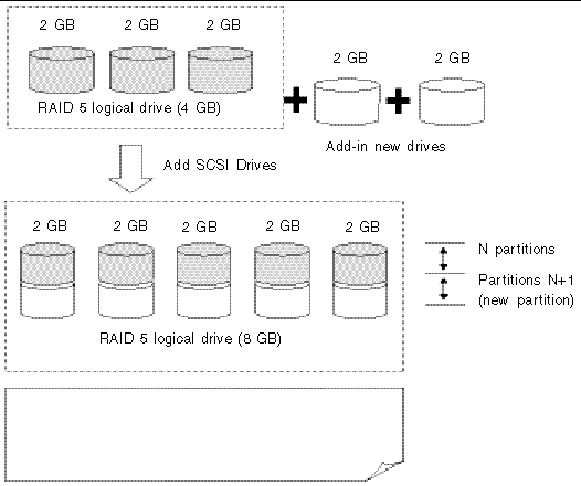
When you add a drive to a logical drive, you add a partition (the size of the new drive) to the logical drive. Therefore, if you have a single 200-Gbyte logical drive and add a 36-Gbyte drive, the total logical drive is 236 Gbytes with two partitions (one 200-Gbyte partition and one 36-Gbyte partition).
The new partition must be mapped to a host LUN for the HBA to recognize its presence. If you want to add the new partition into an existing partition, operating environment support is necessary.
Expanding logical drives by adding more hard disk drives cannot be canceled once begun. If a power failure occurs, the expansion pauses and the controller does not automatically continue the expansion when the power comes back on. Restarting of the RAID expansion must be performed manually.
If a member drive of the logical drive fails during RAID expansion, the expansion pauses. The expansion resumes automatically after the logical drive rebuild has completed.
After new drives are added, the capacity of the original logical drive is the same and the additional capacity is displayed as another partition (new partition).
When expansion is completed, data is re-striped across the original and the newly added drives. After adding drives, the additional capacity is displayed as a new partition, as shown in FIGURE 3-4.
RAID levels supported: RAID 0, 3, and 5.
1. From the Main Menu, choose "view and edit logical drive."
|
Note - Only logical drives that are configured as RAID 0, RAID 3, or RAID 5 support expansion by adding physical drives. |
A confirmation prompt is displayed.
5. A list of available drives is displayed.
6. Select one or more drives to add to the target logical drive and press Return.
The selected drive is indicated by an asterisk (*) mark.
7. Press Esc when all physical drives have been selected.
8. Press Esc again to display a status bar that indicates the percentage of progress.
A notification message informs you when the process is complete.
The capacity of the added drive is displayed as an unused partition.
The added capacity is included in the logical drive automatically, meaning that you do not have to perform "Expand logical drive" later.
|
Note - If the logical drive has already been mapped with a host LUN, you have to map the added capacity to another host ID/LUN to make use of it. |
In the previous "view and edit Host luns" example, the original capacity is 9999 MB, its host LUN mapping remains unchanged, and the added capacity is displayed as a second partition.
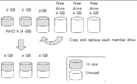
You can expand a logical drive by copying and replacing all member drives with drives of higher capacity. The capacity of member drives are copied and replaced one by one onto drives of larger capacity.
When all the member drives have been replaced, execute the "Expand logical drives" function to make use of the unused capacity.
RAID levels supported: RAID 0, 3, and 5.
1. From the Main Menu, choose "view and edit Logical drives."
2. Select a target logical drive.
3. Choose "cOpy and replace drive."
The member drives belonging to the selected logical drive are listed.
4. Select the member drive (the source drive) that you want to replace with a larger one.
5. Select one of the member drives as the source drive (status indicated as ON-LINE).
A table of available SCSI drives is displayed.
6. Select a new drive onto which you will copy the content of the source drive.
The channel number and ID number of both the source drive and the destination drive are displayed in a confirmation message.
7. A notification message is displayed.
8. Press Esc to view the progress.
A notification message informs you when the process is complete.
9. Repeat these steps to copy and replace every member drive with drives of higher capacity as needed.
You can now perform "Expand logical drive" to make use of the capacity brought by the new drives and then map the additional capacity to a host LUN.
You can make use of unused capacity in a logical drive by expanding the logical drive.
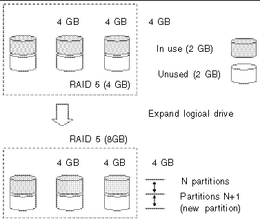
An unused capacity is usually created by replacing the original members with drives of larger capacity or by adding new drives to a logical drive. After a logical drive is expanded, the additional capacity is displayed as a new partition.
RAID levels supported: RAID 0, 1, 3, and 5.
The new partition must be mapped to a host LUN in order for the HBA to recognize its presence. To add the new partition into an existing logical drive, operating system support is needed.
In the following example, the logical drive is originally composed of three member drives and each member drive has the capacity of 1 Gbyte. The "Copy and Replace" function has been performed on the logical drive and each member drive has been replaced by a new drive with the capacity of 2 Gbytes. The next step is to perform the "Expand logical drive" function so you can access the additional capacity of the new drives.
1. Choose "view and edit Logical drives" from the Main Menu.
2. Select the logical drive with its members copied and replaced.
3. Choose "Expand logical drive."
Drive capacity information is displayed.
4. Proceed by pressing Return, or by entering any value no larger than the "maximum drive expand capacity" and then pressing Return.
A confirmation message is displayed.
A notification message informs you when the process is complete.
6. Press Esc to return to the previous menu screen.
The total capacity of logical drive has been expanded to 6 Gbytes.
Copyright © 2004, Sun Microsystems, Inc. All rights reserved.