| C H A P T E R 5 |
|
Viewing and Editing Host LUNs |
The "view and edit Host luns" command allows you to map logical groups or logical volumes to the desired host channels. Each logical drive (LD) or logical volume (LV) can be mapped more than once to achieve a redundant data path, using multipathing software.
Topics covered in this chapter include:
A logical unit number (LUN) is a unique identifier used on a SCSI channel that enables a host to differentiate between separate devices.
Once you have created logical drives or logical volumes, you can map each storage partition as one system drive (host ID/LUN). The host adapter recognizes the system drives after reinitializing the host bus.
|
Note - The UNIX format and Solaris probe-scsi-all commands do not display all mapped LUNs if there is not a logical drive mapped to LUN 0. |
An FC channel can connect up to 126 devices. Each device has one unique ID.
A SCSI bus channel can connect up to 15 devices (excluding the controller itself) when the Wide function is enabled (16-bit SCSI). Each device has one unique ID.
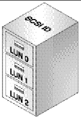
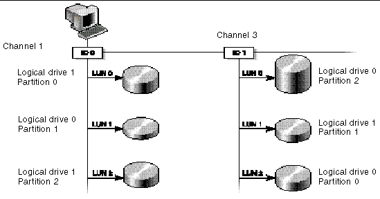
FIGURE 5-1 illustrates the idea of mapping a system drive to a host ID/LUN combination.

Each ID/LUN looks like a storage device to the host computer.

If you want to create 128 LUNs, which is the maximum number of storage partitions that can be mapped for a SCSI RAID array, you need to set up one of the following configurations:
For details on how to add host IDs, refer to Creating Additional Host IDs.
|
Note - For an overview of how partitions, LUNs, and host IDs work, refer to Mapping Logical Drive Partitions to Host LUNs. |
1. Create a minimum of four host IDs.
By default, you have two host IDs:
You can have a total of two IDs per channel, one for the primary controller and one for the secondary controller.
For the detailed procedure, refer to Creating Additional Host IDs.
2. Confirm that the allowed number of LUNs per host ID is 32.
a. Choose "view and edit Configuration parameters  Host-side SCSI Parameters."
b. If "LUNs per Host SCSI ID" is not set to 32, choose "LUNs per Host SCSI ID - 32 LUNS."
3. Create at least four logical drives.
Refer to Creating Logical Drives for more information.
4. For each logical drive, create a number of partitions per logical drive until you reach a total of 128 partitions.
5. Map those partitions to the host IDs.
For the detailed procedures, refer to Partitioning a Logical Drive and Mapping Logical Drive Partitions to Host LUNs.
For FC arrays in loop configurations, if you want to create the maximum number of storage partitions that can be mapped for a Fibre Channel RAID array (1024), set up the following configuration:
1. If necessary, edit "Host-side SCSI Parameters" so that "LUNs Per Host SCSI ID" is set to 32.
See Host-side SCSI Parameters Menu Options for more information.
2. Keep the four default host channels (CH 0, 1, 4, and 5).
3. Create eight host IDs per host channel (four primary controller IDs and four secondary controller IDs per host channel) for a total of 32 host IDs.
For the detailed procedure, see Creating Additional Host IDs.
4. Create eight logical drives.
For the detailed procedure, see Creating Logical Drives.
5. Partition each logical drive into 128 partitions (8 times 128 = 1024).
6. Map the 1024 partitions to the 32 host IDs.
For the detailed procedures, see Partitioning a Logical Drive and Mapping Logical Drive Partitions to Host LUNs.
For FC arrays in point-to-point configurations that use redundant controllers to ensure maximum reliability, accessibility, and serviceability (RAS), you can have a maximum of 64 LUNs. To achieve this redundancy with a maximum number of LUNs, you need to use multipathing software on each host accessing the array.
For example, to set up 64 LUNs with multipathing enabled, you can map 32 LUNs to channel 0 on one controller and channel 1 on the other controller, and map the other 32 LUNs to channel 4 on one controller and channel 5 on the other controller.
Refer to Sun StorEdge 3000 Family Installation, Operation, and Service Manual for more information about point-to-point configurations, including configuring a maximum number of LUNs with redundant controllers and automatic failover. Refer to the Sun StorEdge 3000 Family Best Practices Manual for your array to see more information about point-to-point and loop storage area network (SAN) and direct-attached storage (DAS) configurations.
|
Note - The illustrations in this section depict a FC array, but SCSI arrays follow the same procedure. |
1. Choose "view and edit Host luns" from the Main Menu.
A list of available channels and their associated controllers is displayed.
2. Select the desired channel and ID to which the logical drive will be mapped.
3. If you see "Logical Drive" and "Logical Volume" menu options, choose "Logical Drive."
4. Using the arrow keys, select the desired LUN.
A list of available logical drives is displayed.
|
Note - The Sun StorEdge Configuration Service program requires that a device is mapped to LUN 0 as a minimum. |
5. Select the desired logical drive (LD).
The partition table is displayed.
6. Select the desired partition.
Two mapping options are displayed:
7. Choose the mapping option that is appropriate for your network and proceed with Using the Map Host LUN Option or Creating Host Filter Entries (FC Only).
Each partition must be mapped to a host LUN. Multiple partitions can be mapped to the same host LUN. The "Map Host LUN" menu option is used with all SCSI arrays, and with FC arrays when multiple hosts are not on the same loop.
|
Note - This procedure is applicable to both SCSI and FC arrays. The illustrations show FC examples. |
To map partitions with the host filter entry option, see Creating Host Filter Entries (FC Only).
1. After the completion of the steps in Mapping a Partition to a LUN, choose "Map Host LUN."
2. Confirm the mapping scheme by choosing Yes.
The partition is now mapped to a LUN.
3. Press the Esc key to return to the Main Menu.
4. Repeat Step 1 through Step 3 for each partition until all partitions are mapped to LUNs.
5. To verify unique mapping of each LUN (unique LUN number, unique DRV number, or unique Partition number), choose "view and edit Host luns."
6. Select the appropriate controller and ID to review the LUN information.
|
Note - If you are using host-based multipathing software, map each partition to two or more controller/ID combinations in order to make multiple paths to the same LUN available to the host. |
The following SCSI array example screens illustrate four channel IDs with eight LUNs per channel:
This section provides the procedure for deleting a host LUN mapping
1. Choose "view and edit Host luns" from the Main Menu.
2. Highlight the channel and ID that are mapped to the host LUN.
3. Highlight the specific host LUN.
4. Choose Yes to delete the host LUN.
This option deletes the logical drive or logical volume mapping to the host channel. This option does not delete the data contained within the logical drive.
|
Note - All host LUN mappings are removed when there is any partition change. |
For multiple servers connected to the same Sun StorEdge 3510 FC array, LUN filtering organizes how the array devices are accessed and viewed from host devices. LUN filtering is used to provide exclusive access from a server to a logical drive and exclude other servers from seeing or accessing the same logical drive.
LUN filtering also enables multiple logical drives or partitions to be mapped to the same LUN number, allowing different servers to have their own LUN 0. LUN filtering is valuable in clarifying mapping when each HBA typically sees twice the number of logical drives when viewed through a hub.

An advantage of LUN filtering is that it allows many hosts to attach to an array through a common Fibre Channel port and still maintain LUN security.
Each Fibre Channel device is assigned a unique identifier called a world wide name (WWN). A WWN is assigned by the IEEE and stays with the device for its lifetime. LUN filtering uses the WWN to specify which server is to have exclusive use of a specific logical drive.
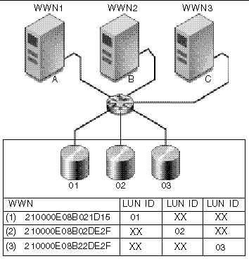
As shown in FIGURE 5-3, when you map LUN 01 to host channel 0 and select WWN1, server A has a proprietary path to that logical drive. All servers will continue to see and access LUN 02 and LUN 03 unless filters are created on them.
Prior to using LUN filtering, you need to identify which Sun StorEdge 3510 FC array is connected to which HBA card, and the WWN assigned to each card.
1. If you have a new HBA device installed on your computer, reboot the computer.
2. Type the following command:
3. Scroll down the listing to see the Fibre Channel devices and the related WWNs.
1. Boot a specific host, and note the BIOS version and HBA card models connected to your host.
2. Access the HBA card's BIOS with the appropriate command (Alt-Q or Ctrl-A are commonly used).
If the host has multiple HBA cards, select the card that is connected to the storage.
3. Scan the card to look for devices attached to it (usually with the Scan Fibre Devices or the Fibre Disk Utility).
The node name (or similar label) is the WWN. The following example shows the node name for a Qlogic card.
Refer to appendixes in the Sun StorEdge 3000 Family Installation, Operation, and Service Manual for the Sun StorEdge 3510 FC Array to see information about determining the WWN for servers running HP-UX or IBM AIX, and for more detailed information regarding WWNs on all supported platforms.
Host filter entries enable you to assign exclusive access to a logical drive to a specific host. Otherwise, in some configurations, multiple hosts would be able to view and access the same drive.
When you create a host filter entry you are also mapping each partition to a specific host, so the procedure described in this section is used instead of the procedure described in Using the Map Host LUN Option.
|
Note - If you plan to map hundreds of LUNs, the process is easier if you use the Sun StorEdge Configuration Service program. |
1. After the completion of the steps in the procedure Mapping a Partition to a LUN, choose "Create Host Filter Entry  Add from current device list."
2. From the device list, select the server WWN number for which you are creating a filter.
3. At the confirmation screen, choose Yes.
4. Review the filter configuration screen. Make any changes necessary by using the arrow keys to select an item.
|
Note - If you press Return to change the first item displayed, which is the logical drive and partition assignment, press Esc and repeat the "Create Host Filter Entry" procedure. |
5. If you want to edit the WWN, choose "Host-ID/WWN."
6. Make the desired changes and press Return.

|
Caution - Be sure that you edit the WWN correctly. If the WWN is incorrect, the host will be unable to recognize the LUN. |
7. To edit the WWN Mask, use the arrow keys to select "Host-ID/WWN Mask" and press Return.
8. If you want to change the filter setting, which toggles between "Include" and "Exclude," choose "Filter Type -."
9. At the confirmation screen, choose Yes.
10. If you want to change the access mode, which toggles between "Read/Write" and "Read Only," use the arrow keys to choose "Access mode -."
11. At the confirmation screen, choose Yes.
12. If you want to set a name, choose "Name -."
13. Type the name you want to use for this filter and press Return.
14. Verify all settings and press Esc to continue.
15. At the confirmation screen, choose Yes.
16. At the Host-ID/WWN list, repeat the previous steps to create additional filters, or press Esc to continue.
|
Note - Unlike most firmware operations where you must complete each entry individually and repeat the procedure if you want to perform a similar operation, you can add multiple WWNs to your list before you actually create the host filter entry in Step 17. Be sure to follow the instructions carefully. |
17. At the confirmation screen, verify the settings and choose Yes to complete the host LUN filter entry.
A mapped LUN displays a number and a filtered LUN displays an "M" for masked LUN in the host LUN partition window.
1. Choose "view and edit Host luns."
2. Select the channel and ID that are mapped to the host LUN.
4. Choose "View and edit host filtering."
5. Select the Host-ID/WWN whose information you want to view or edit.
6. Choose "View Host Filter Information" to see detailed information about that filter.
7. Choose "Add Host Filter Entry" to add another filter. See To Create Host Filter Entries for the steps to follow once you choose this menu option.
8. Choose "Delete Filter Entry" to delete the current filter.
9. Choose "Add Host-ID/WWN Name List" to manually add a WWN. See To Create Host Filter Entries for the steps to follow once you choose this menu option.
Copyright © 2004, Sun Microsystems, Inc. All rights reserved.