| C H A P T E R 6 |
|
Viewing and Editing SCSI Drives |
This chapter explains how to view and edit physical drive parameters. Topics covered include:
To view and edit physical drive parameters, choose "view and edit scsi Drives" from the Main Menu, which displays the SCSI drive status table. In this status table you can view all the SCSI drives associated with the selected logical drive. Each drive's channel, ID, status, and model number is displayed in the table. The SCSI Enclosure Services (SES) device or SAF-TE device that monitors the array's environmental conditions is also included in this table.
To modify configuration information or view additional information, select a drive from the SCSI drive table. When you press Return, you see a menu of available options. See Viewing Drive Information for a description of the details that are available.
|
Note - If a drive is installed but not listed, the drive might be defective or installed incorrectly. |
When the array is powered up, the controller scans all physical drives that are connected through the drive channels. If a physical drive is connected after the controller completes initialization, use the "Scan scsi drive" submenu option after you have selected a drive so the controller can recognize the newly added physical drive. Then you can configure it as a member of a logical drive.
A physical drive has a USED status when it was once part of a logical drive but no longer is. This can happen, for instance, when a drive in a RAID 5 array is replaced by a spare drive and the logical drive is rebuilt with the new drive. If the removed drive is later replaced in the array and scanned, the drive status is identified as USED since the drive still has data on it from a logical drive.
When the RAID set is deleted properly, this information is erased and the drive status is shown as FRMT rather than USED. A drive with FRMT status has been formatted with either 64 KB or 256 MB of reserved space for storing controller-specific information, but has no user data on it.
If you remove the reserved space, using the "View and Edit SCSI drives" menu, the drive status changes to NEW.
To handle BAD drives, see Controller Failover. If two drives show BAD and MISSING status, see Recovering From Fatal Drive Failure.
Each SCSI array must be configured as a single-bus configuration or a dual-bus configuration, based on where the SCSI bus cable is attached on the I/O module. For bus configuration details, refer to the Sun StorEdge 3000 Family Installation, Operation, and Service Manual for your array.
The drive-bus configuration determines how drives and drive IDs are assigned to drive channels on the controller.
When an expansion unit is attached to a RAID array, unique, hard-assigned loop IDs are assigned to each expansion unit drive. A loop ID is the decimal version of an AL_PA. The lowest number loop ID is the lowest priority address on the loop.
On the left front side of an expansion unit, an ID switch is used to set the loop IDs for the disk drives to a different range of values so that the same IDs are not repeated on the same loop. Press the button to change the ID number.
By default, the ID switch on all RAID arrays and expansion units is set to 0, where the range of IDs is automatically 0 to 11 for 12 drives (the IDs 12-15 are ignored).
The ID switch offers eight ID ranges. Each set contains 16 IDs (the last four IDs in each range are ignored). These ranges are shown in TABLE 6-2.
A local spare drive is a standby drive assigned to serve one specified logical drive. If a member drive of that logical drive fails, the local spare drive becomes a member drive and automatically starts to rebuild.
|
Note - Logical drives configured with a nonredundant RAID level (RAID 0) do not support spare drive rebuild. |
1. Choose "view and edit scsi Drives."
2. Select the drive you want to designate as a spare.
3. Choose "add Local spare drive."
4. Select a logical drive to assign the local spare to that logical drive.
A confirmation prompt is displayed,
A global spare drive automatically replaces any failed drive in the array.
1. Choose "view and edit scsi Drives."
2. Select the drive you want to designate as a spare
3. Choose "add Global spare drive."
A confirmation prompt is displayed.
Displayed SCSI drive information includes the revision number, serial number, and disk capacity of individual drives. If you select an SES chip rather than a drive, the "View drive information" menu option also displays the Node name (WWN). From this information you can determine the serial number of the chassis, as described in the following procedure.
1. From the Main Menu, choose "view and edit scsi Drives."
2. Select the SCSI drive you want to view.
3. Choose "View drive information."
The drive's revision number, serial number and disk capacity (in blocks of 512K) of the drive are displayed.
If you selected the SES chip rather than a drive, the Node name (WWN) text area displays the worldwide name assigned to the enclosure.
In the example above, the world wide name is shown in hexadecimal format:
The last six hexadecimal digits of the WWN indicate the serial number of the chassis, which is the same as the chassis Field-Replaceable Unit Identifier (FRU-ID). This number is sometimes shown as only the last four hexadecimal digits. In the example above, the FRU-ID is 002F18, or simply 2F18.
Prior to configuring disk drives into a logical drive, you must know the status of physical drives in your enclosure.
1. Choose "view and edit scsi Drives."
2. Use the arrow keys to scroll through the table. Check to see if there are any drives installed but not listed here.
If a drive is installed but not listed, the drive might be defective or installed incorrectly.
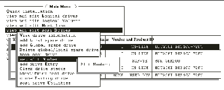
3. If a physical drive was connected after the controller completed initialization, select the drive from the table and press Return. Use the "Scan scsi drive" menu option to recognize the newly added physical drive and to configure it as a member of a logical drive.

|
Caution - Scanning an existing drive removes its assignment to any logical drive. All data on that drive is lost. |
When an array is powered on, the controller scans all physical drives that are connected through drive channels. If a physical drive is connected after the controller completes initialization, use the "Scan scsi drive" menu option
1. Choose "view and edit scsi Drives" from the Main Menu.
2. Select a drive from the SCSI drive table.

|
Caution - Scanning an existing drive removes its assignment to any logical drive. All data on that drive is lost. |
The menu options vary according to the drive status.
5. Select the SCSI ID of the drive you want to scan.
A confirmation prompt is displayed.
This section describes how to delete a local spare or global spare drive.
1. Choose "view and edit scsi Drives" from the Main Menu.
2. Select a local spare drive or a global spare drive.
3. Choose "Delete global/local spare drive."
A confirmation message is displayed.
The status of the spare drive you deleted, or any drive you replaced from a logical unit, is now indicated as a "FRMT DRV."
This function is used to optionally add a slot number identifier in the Slot column of the SCSI drive table. This function has no effect on controller operation.
1. Choose "view and edit scsi Drives" from the Main Menu.
A list of the connected SCSI drives is displayed.
2. Select a drive from the SCSI drive table.

4. Type in a value (0-15) that represents the slot number of the drive.
This value does not need to be the device's predetermined SCSI ID number. The slot number is displayed in the Slot column of the drive information list.
When there is an empty slot (or air management sled) that does not contain a drive, the corresponding SCSI channel/ID does not appear in the drive information list.
You can assign a slot number to the empty slot and add a drive entry in order to use it later when a drive is installed.
This section describes how to delete a slot number of a SCSI drive.
1. Choose "view and edit scsi Drives" from the Main Menu.
2. Select the desired SCSI drive.
3. Choose "Set Slot Number  0."
0."
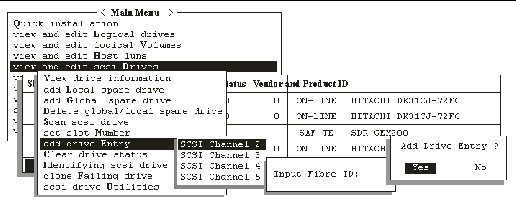
Use the "add drive Entry" menu option to add an additional record to the SCSI drive table prior to adding a SCSI drive.
Use the "Clear drive status" menu option if you want to remove an empty drive designation from the table later.

1. Choose "view and edit scsi Drives" from the Main Menu.
2. Select an insertion spot within the SCSI drive table.
For installed SCSI drives, a table shows the available IDs.
5. Type the desired ID number in the provided text area and press Return.
A confirmation prompt is displayed.
A drive entry is created. Its status is displayed as ABSENT.
1. On the Main Menu, choose "view and edit scsi Drives."
2. Select the desired SCSI drive.
3. Choose "set slot Number  0
0  Clear drive status."
The empty drive entry is removed from the SCSI drive table.
|
Note - You cannot remove an empty drive entry if it has been assigned a slot number. Delete the slot number before removing the empty drive entry. |
With the maturity of industry-standard technologies such as Self-Monitoring, Analysis and Reporting Technology (SMART), disk drive failures can sometimes be predicted before they happen. Encountering drive bad block reassignments is one common predictor of a drive that is about to fail.
System administrators can decide when to substitute a healthy drive for a drive showing symptoms of impending failure. This section discusses manual and automated procedures for averting disk failures.
To assist fault prevention, a system administrator can manually clone a disk drive that shows signs of failing, choosing a convenient time when system performance will not be adversely affected.
|
Note - The "Clone Failing Drive" menu option is not displayed with RAID 1 logical drives because its use is not supported in RAID 1 configurations. |
Use the Clone Failing Drive menu option when:
There are two options for cloning a failing drive:
These options are described in the following sections.
Data on the source drive (the drive with the predicted error or any selected member drive) is cloned to a standby spare. The spare then becomes the new source drive. The status of the original source drive is redefined as a "USED DRIVE." System administrators can replace the used drive with a new one, and then configure the new drive as a spare drive.
1. Choose "view and edit scsi Drives."
2. Select the member drive that you want to clone.
3. Choose "clone failing drive."
This option is displayed only if there is a standby drive available.
4. Choose "Replace After Clone."
The controller automatically starts the cloning process using the existing standby (local or global spare drive) to clone the source drive (the target member drive with a predicted error).
5. A notification message is displayed.
The cloning process is indicated by a status bar.
7. Select the drive indicated as "CLONING."
|
Note - To quit the status bar, press Esc to return to the table of SCSI drives. |
8. Choose "clone Failing drive" again to view the current status.
|
Note - You can identify the source drive and choose "View clone progress," or choose "Abort clone" if you selected the wrong drive. |
When the process is completed, the following message is displayed.
Data on the source drive (the drive with a predicted error or any selected member drive) is cloned to the standby spare, but the spare does not become the new source drive. The standby spare drive clones the source drive without substituting it.
The status of the spare drive is displayed as a CLONE drive as soon as the cloning process is complete. The source drive remains a member of the logical drive.
1. Choose "view and edit scsi Drives" from the Main Menu.
2. Select the member drive with a predicted error.
3. Choose "clone Failing drive  Perpetual Clone."
A confirmation message is displayed.
The controller automatically starts the cloning process, using the existing standby (local or global spare drive) to clone the source drive.
|
Note - If there is no standby drive (local or global spare drive), you must add a new drive and configure it as a standby drive. |
A notification message is displayed when the cloning process begins:
5. Press Esc to view current progress on a status bar.
6. To quit viewing the status bar, press Esc to return to the previous menu screen.
7. Select the drive indicated as "CLONING" by pressing Return.
8. Choose "clone Failing drive" again to view the progress.
|
Note - You can identify the source drive and choose "View clone progress." Choose "Abort clone" if you have selected the wrong drive. |
A notification message informs you when the process is complete.
9. Press Esc to clear the notification message and to see the SCSI drives' status after the cloning process.
The source drive (Channel 1 ID 5) remains as a member of logical drive 0, and the standby drive (Channel 1 ID 2, the local or global spare drive) becomes a CLONE drive.
While a cloning operation is underway you can examine its status, including the operation's progress and the identity of the target drive.
1. Choose "view and edit Scsi drives" from the Main Menu.
The SCSI drive table is displayed.
2. Select the target drive whose status is CLONING.
3. Choose "clone Failing drive" to identify the source drive that is being cloned and to see a menu whose options enable you to display the progress of the cloning operation or abort the cloning operation.
|
Note - If you are viewing an active monitoring session with Sun StorEdge Configuration Service software, the progress of the cloning operation is displayed by the Controller Array Progress bar. |
SMART is an industry-standard technology that provides near-term failure prediction for disk drives. When SMART is enabled, the drive monitors predetermined drive attributes that are susceptible to degradation over time. If a failure is likely to occur, SMART makes a status report available so that the host can prompt the user to back up data on the failing drive.
Not all failures can be predicted, however. SMART predictability is limited to the attributes the drive can monitor that are selected by the device manufacturer, based on the attribute's ability to contribute to the prediction of degrading or fault conditions.
Although SMART attributes are drive-specific, a variety of typical characteristics can be identified:
Sun StorEdge 3000 family arrays implement the ANSI-SCSI Informational Exception Control (IEC) document X3T10/94-190 standard.
Sun StorEdge 3000 family array firmware supports four manual selections related to SMART function in firmware:
If the drive whose failure has been predicted does fail subsequently, the clone drive takes over immediately.
This section describes how to configure the SMART settings you want.
1. Choose "view and edit Configuration parameters  Drive-side SCSI Parameters
  Periodic Drive Check Time."
A confirmation message is displayed.
4. Choose "Drive-side SCSI Parameters  Drive Predictable Failure Mode (SMART)."
5. Choose one of the menu options from the "Drive Predictable Failure Mode (SMART)" menu.
6. Determine whether your drives support SMART.
a. From the "View and Edit SCSI Drives" menu, select one drive to test.
A "Predictable Failure Test" menu option is displayed.
|
Note - If the SMART feature is not properly enabled, this menu option is not displayed. |
b. Choose "Predictable Failure Test."
A confirmation prompt is displayed.
The drive simulates a predictable drive error.
The next time the controller performs the periodic drive check, the controller detects the error simulated by the drive and displays an error message.
|
Note - The "(TEST)" component of the message indicates that no predictable failure was actually detected and no action is necessary. |
This section describes setting SMART to only detect future problems and not attempt to fix them.
1. Choose "Drive-side SCSI Parameters  Drive Predictable Failure Mode (SMART)
  Detect Only."
Whenever a drive predicts symptoms of predictable drive failure, the controller writes an error message to the event log.
This section describes setting SMART to detect future problems and clone a spare drive so that it is ready when failure does occur.
1. Choose "Drive-side SCSI Parameters  Drive Predictable Failure Mode
  Detect and Perpetual Clone."
2. Assign at least one spare drive to the logical drive (either a local spare or global spare).
When a drive (logical drive member) detects a predictable drive failure, the controller clones the drive to a spare drive.
3. To see the status of the source drive or the cloning progress, or to cancel the cloning process, from the "View and Edit SCSI Drive" menu select the spare drive (either local or global) and choose the appropriate menu option.
|
Note - The spare drive stays mirrored to the source drive (the drive whose failure has been predicted) but does not replace it until the source drive fails. |
This section describes setting SMART to detect future problems, clone a spare drive, and immediately use the cloned drive to replace the original drive whose failure is predicted.
1. Choose "Drive-side SCSI Parameters  Drive Predictable Failure Mode (SMART)
  Detect and Clone+Replace."
2. Assign at least one spare drive (either local or global) to the logical drive.
When a drive failure is predicted, the controller clones that drive to a spare drive. After the clone process is complete, the controller immediately replaces the source drive (the drive whose failure has been predicted). The status of the source drive then is changed to a used drive, and you can replace this drive with a new one.
|
Note - If you want to see the progress of cloning, press Esc to clear the notification message and see the status bar. |
If there is a failed drive in a RAID 5 logical drive, replace the failed drive with a new drive to keep the logical drive working.
|
Note - The following procedure works only if there is no I/O activity. |
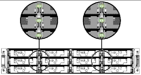
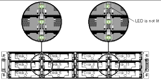
To find a failed drive, identify a single drive, or test all drive activity LEDs, you can flash the LEDs of any or all drives in an array. Since a defective drive does not light up, this provides a good way for you to visually identify a failed drive before replacing it.
1. On the Main Menu, choose "view and edit scsi Drives."
2. Select the drive you want to identify.
3. Choose "Identify scsi drive  flash All drives" to flash the activity LEDs of all of the drives in the drive channel.
The option to change the Flash Drive Time is displayed.
4. Change the duration if you want and press Return.
A confirmation message is displayed.
The read/write LED of a failed hard drive does not light. The absence of a lit LED helps you locate and remove the failed drive.
In addition to flashing all drives, you can flash the read/write LED of only a selected drive or flash the LEDs of all drives except the selected drive, using steps similar to those outlined in this section. These three drive-flashing menu options are described in the remainder of this section.
The read/write LED of the drive you select lights steadily for a configurable period of time from 1 to 999 seconds.

The "Flash All SCSI Drives" menu option lights LEDs of all good drives but does not light LEDs for any defective drives.

With this menu option, the read/write LEDs of all connected drives except the selected drive lights for a configurable period of time from 1 to 999 seconds.

Do not use the "scsi drive Utilities" menu option. These utilities are reserved for specific troubleshooting methods and should be used only by qualified technicians.
1. Choose "view and edit scsi Drives" from the Main Menu.
2. Select the drive that the utility is to performed on.
3. Choose "scsi drive Utilities  SCSI Drive Low-level Format" or "scsi drive Utilities
  Read/Write Test."

|
Caution - All data on the disk drive is destroyed when you use this command. |
The SCSI disk drive on which a low-level disk format will be performed cannot be a spare drive (local or global) nor a member drive of a logical drive. "Disk Reserved space" must be removed before this menu option appears. See Changing Disk Drive Reserved Space for more information.
The "SCSI Drive Low-level Format" menu option appears only if the drive status is a NEW or USED drive.
1. Choose "view and edit scsi Drives" from the Main Menu.
2. Select a new or used drive that the utility is to performed on.
3. Choose "scsi drive Utilities  scsi Drive Low-level Format."
A confirmation message is displayed.
This section describes how to perform a read/write test.
1. Choose "view and edit scsi Drives" from the Main Menu.
2. Select a new or used drive on which the utility is to be performed.
3. Choose "scsi drive Utilities  Read/Write Test."
4. Enable or disable the following options and press Return after each change.
5. When configuration is complete, choose "Execute Drive Testing."
The Read/Write test progress is indicated by a status bar.
|
Note - At any time you can press Esc, choose "Read/Write Test," and then choose "View Read/Write Testing Progress" or "List Current Bad Block Table." |
|
Note - If you want to stop testing the drive, choose "Abort Drive Testing." |
Before a disk can be included in a logical drive, the RAID controller needs to format an amount of space for storing controller-specific data separately from user data. The default reserved space is 256 MB, but older drives might have only 64 KB of reserved space. Use the default value unless you are using an older (non-upgraded) version of controller firmware that can only recognize 64 KB of reserved space.
|
Note - It is preferable to upgrade your controller firmware rather than make your drive reserved space backward-compatible. |
1. Make sure the drive is not part of a logical drive.
1. Choose "view and edit scsi Drives" from the Main Menu.
2. Select the drive whose reserve space you want to change.
3. Choose "disk Reserved space - "
If reserved space currently exists, a confirmation prompt asks if you want to remove the reserved space.
The "disk Reserved space - " menu option now indicates that the reserved space is unformatted.
5. Choose "disk Reserved space - " again if you want to allocate reserved space.
6. Choose either "256 MB" or "Backward-Compatible (64KB)" to allocate reserved space.
A confirmation prompt asks if you want to format disk reserved space.
Copyright © 2004, Sun Microsystems, Inc. All rights reserved.