| Skip Navigation Links | |
| Exit Print View | |

|
Sun ZFS Storage 7x20 Appliance Customer Service Manual |


Power Distribution, Fan Module and Disk Components
Standalone Controller Configurations
7320 CPU and Memory Components
7320 Power Distribution and Fan Module Components
7320 Single and Cluster Controller Configurations
7420 Standalone and Cluster Controller Configurations
7720 Cluster Controller Configurations
7x20 and 7700 CRU Maintenance Procedures
Required Tools and Information
7x20 Controller Replacement Tasks
7x20 Cabinet Replacement Tasks
Disk Shelf Maintenance Procedures
Electrostatic Discharge Precautions
This page contains information and instructions to help prepare you for servicing replaceable components in the Sun ZFS Storage 7700 appliance. For instructions on how to replace appliance components or for more information about the system controller, refer to the following pages:
Controller Tasks - replace controller or cabinet CRU components
7420/7720 Hardware Overview - view storage controller component diagrams, specifications, and cluster options
The Sun ZFS Storage 7700 appliance cabinet houses all of the components that support a clustered storage system. The cabinet includes 12 cages that host 30 hard disk drives (HDDs), 2 leaf controller cards (LCCs), and 2 optional Logzilla solid state drives (SSDs). To control these resources, the appliance includes 2 system controllers and 2 rack controller cards (RCCs) on internal and external SAS and Ethernet networks. To power and cool the components, the cabinet includes 6 power supplies (PSUs) and 3 fan trays.
The lower cabinet is populated with 2 3U Sun ZFS 7720 storage controllers containing 4-socket CPU motherboards with large memory capacities, 4 optional read-optimized Readzilla SSDs and 10 PCIe slots with installed adapters that are clustered by default in a high availability configuration.
The following illustration shows the 7700 front panel (left) and rear panel
(right) of the main cabinet. 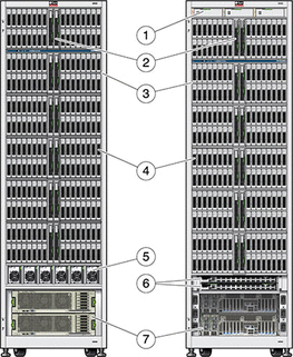
| ||||||||||
Refer to http://www.sun.com/storage/disk_systems/unified_storage/7700/specs.xml for the most recent component specification.
|
This section includes descriptions about the main components included in the 7700 main cabinet.
The 7700 appliance is shipped with installed external cables located behind the cabinet doors. SAS cables connect the RCCs to the storage controllers, and Ethernet cables connect the internal Ethernet bus between the system controllers.
The external cables consist of power and data cables. The power cables
(1) connect the power supplies and system controllers in the main cabinet
to the power circuits (2 and 3) in the facility that connect
to the power sources (4 and 5). 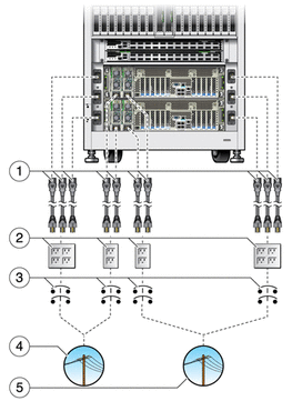
The following illustration shows the data cables that create the default cluster
configuration between the system controllers and the RCCs. 
Each 7700 cabinet comes with three fan trays that each host three fan modules. Individual fan modules cannot be replaced; the entire fan tray must be replaced.
Caution: Operating a cabinet for an extended period of time with a
fan tray removed reduces the effectiveness of the cooling system, and may
initiate an emergency thermal shutdown. Unpack the replacement fan tray in advance,
and insert it into the cabinet as soon as the faulted fan
tray is removed. Cooling for the 7720 controllers is independent from that
of the 7700 cabinet, but the same guidelines apply when replacing fans
in a controller. 
The 7700 appliance cabinet hosts 12 drive cages (6 on each side).
Each cage hosts 30 HDDs, 2 SSDs and 2 LCCs. Drives can
be hot-swapped. 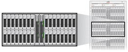
The leaf controller cards (LCCs) are the final SAS fan out to the HDDs that are the leaves in the SAS topology. Each drive cage has 2 LCCs that are load-balanced. In the event of a fault, one LCC provides connectivity to the HDDs. The LCCs can be hot-swapped without shutting down the appliance. If both an LCC and RCC (see below) are being replaced at the same time, replace the RCC first.

Each 7700 cabinet comes with 6 power supplies near the bottom of
the cabinet. The power supplies can be hot-swapped while the system is
running. The system controllers also have power supplies. See the 7x20 Overview
for more information. 
The 7700 appliance contains two RCCs that are located between the storage
controllers and the drive cages. In the event of an RCC failure,
one RCC can provide connectivity to both system controllers and the drive
cages. The RCCs are the primary interface to the storage controllers and
the root of the SAS topology. The RCCs are hot-swappable, but they
must be replaced by a Sun service technician. If both an
RCC and one or more LCCs are being replaced at the same
time, replace the RCC first. 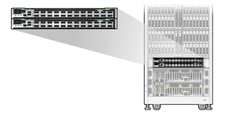
All of the drive cages and both system controllers use SSDs as part of the hybrid storage pool, seamlessly adding flash into the storage hierarchy for performance. Slots 30 and 31, if populated, are dedicated to write-optimised SSDs. Zero to 2 SSDs may optionally be present in each cage. Populate all of the drive cages containing LCCs with one SSD in slot 30 before adding a second SSD to any of the cages.
The minimum SSD configuration is four SSDs per base cabinet. Refer to 7420/7720 CPU and Memory components for other storage controller component guidelines.
The following sections contain descriptions of the internal components in the Sun ZFS Storage 7700 appliance. Note: All internal components must be serviced by a Sun Service technician.
The internal cables deliver power to the components and plumb the necessary SAS and Ethernet connections between the backplanes, storage controllers and RCCs. All cabling connections are shown in the cabling label on the inside of the cabinet. Failed internal cables must be replaced by a Sun Service technician.
The 7700 cabinet includes several internal interface boards. There are no CRUs inside the 7700 cabinet, and access to the internal interface boards is limited to Oracle's Sun Service technicians.
Fan Tray Backplane - Provides power to the fan trays and the system indicators. The fan tray backplane also provides an interface between the system software and the system indicators.
HDD Backplane - Delivers power and data connections to the HDDs, SSDs and LCCs.
System Indicator Boards - Provides system-level status indicators on the front and rear panels under the top drive cage.
Power Distribution Backplane - Distributes power from the power supplies to the other components in the cabinet, except for the system controllers and Ethernet switch.
RCC Backplane - Interface card between the RCC and the Disk Cage backplanes. The RCC backplane also delivers power to the RCCs.


|