| Skip Navigation Links | |
| Exit Print View | |

|
Sun ZFS Storage 7x20 Appliance Customer Service Manual |


Power Distribution, Fan Module and Disk Components
Standalone Controller Configurations
7320 CPU and Memory Components
7320 Power Distribution and Fan Module Components
7320 Single and Cluster Controller Configurations
7420 Standalone and Cluster Controller Configurations
7720 Cluster Controller Configurations
7x20 and 7700 CRU Maintenance Procedures
Required Tools and Information
7x20 Controller Replacement Tasks
7x20 Cabinet Replacement Tasks
This section provides procedural details for customer replaceable units (CRUs) of any disk shelf in the Sun ZFS Storage 7000 family of products. Refer to Disk Shelf Overview for component specifications and diagrams.
Read the information in the overview section for your controller and become familiar with the replaceable parts of the system:
Follow the instructions in the Electrostatic Discharge Precautions section.
Legacy platform overviews for 7110, 7210, 7310, 7410, and J4400/J4500 Disk Shelf are provided in those sections of the Sun Storage 7000 Unified Storage System Service Manual.
Follow all Sun cautions, warnings, and instructions marked on the equipment and described in Important Safety Information for Sun Hardware Systems located at http://dlc.sun.com/pdf/816-7190-12/816-7190-12.pdf.
Remove all plastic, vinyl, and foam material from the work area.
Wear an antistatic wrist strap at all times when handling any CRU.
Before handling any CRU, discharge any static electricity by touching a grounded surface.
Do not remove a CRU from its antistatic protective bag until you are ready to install it.
After removing a CRU from the chassis, immediately place it in an antistatic bag or antistatic packaging.
Handle any card that is part of a CRU by its edges only and avoid touching the components or circuitry.
Do not slide a CRU over any surface.
Limit body movement (which builds up static electricity) during the removal and replacement of a CRU.
The shelf drives are hot-swappable and may be replaced without removing power from the shelf. The replacement drive must be of the same capacity and type as the drive to be replaced. To avoid possible data loss when removing non-faulted drives, label each drive with the number of the slot from which it was removed and reinstall each drive into the same slot.
Faulted drives are indicated by an amber LED. Go to the Maintenance
> Hardware section of the BUI and double click the shelf thumbnail
to view Details for HDDs or  to turn on the locator
LED.
to turn on the locator
LED.
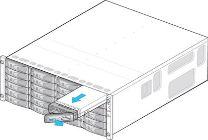
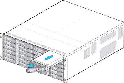
 for the controller and then click HDD to verify that the
  icon is green for the newly installed disk.
The power supplies are hot-swappable and can be replaced without removing power
from the system. The power supplies can produce high energy hazard and
should only be replaced by instructed individuals with authorized access to the
equipment. Failed power supplies are indicated by an amber LED on the
rear panel, see the Shelf Rear Panel illustration. Go to the Maintenance > Hardware
screen of the BUI. Double click the shelf and then click PSU
to view details or to turn on the locator LED.
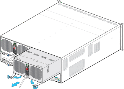
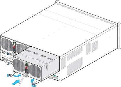 for the controller and then click PSU to verify that the
icon is green for the newly installed power supply.
for the controller and then click PSU to verify that the
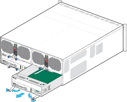
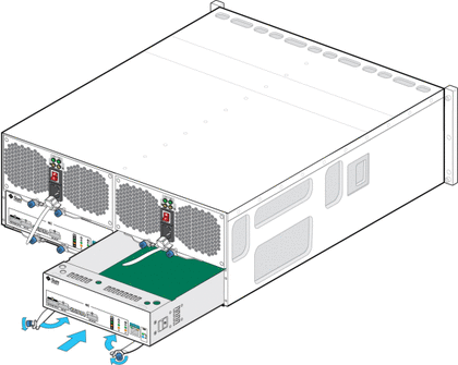
icon is green for the newly installed power supply.The SIM boards are hot-swappable so you can replace them without removing power to the system. The SIM boards are multi-pathed, so you can remove one of the SIM boards at any time, regardless of the state of the blue SIM OK indicator. A faulted SIM board is indicated by an amber LED.


|