| Oracle® Communications IP Service Activator Network and SLA Monitoring Guide Release 7.2 E47717-01 |
|
|
PDF · Mobi · ePub |
| Oracle® Communications IP Service Activator Network and SLA Monitoring Guide Release 7.2 E47717-01 |
|
|
PDF · Mobi · ePub |
This chapter provides information about using Service Assurance Agent (SAA) Measurement with Oracle Communications IP Service Activator.
Service Assurance Agent (SAA) is a Cisco technology that measures key SLA metrics such as response time, network resources, availability, jitter, connect time and packet loss between two devices (CE to CE, or between Virtual CEs, or between a CE and Virtual CE - in this chapter, the term ’device' can refer to a CE or a Virtual CE). Figure 2-1 illustrates this concept.
For measurements to or from a Virtual CE, you drag the CE device into the SAA VPN site and you also add the Virtual CE object. After this is completed, you can perform measurements between Virtual CEs and between CEs and Virtual-CEs in addition to CE to CE measurements.
SAA is also referred to as Response Time Reporter (RTR).
Note:
IPv6 SAA is implemented as IP SLA rather than RTR.SAA's measurement features are built into the Cisco IOS software, supporting response time monitoring without the need to purchase and deploy additional equipment and software in the network. This feature may represent significant cost and management savings.
For information on device and IOS support, see IP Service Activator Cisco IOS Cartridge Guide.
When you apply SAA to a VPN, Oracle Communications IP Service Activator tests the connection between pairs of sites in the VPN. The SAA operation that performs the test is configured at the device level.
Also known as probes, SAA operations collect response time and availability information. An operation is configured on a device and tests the connection to a target device by placing synthetic packets in the network. The packets simulate other forms of network traffic, depending on the type of operation that has been configured. Each SAA operation has a unique ID number that enables tracking of the operation.
This section details how different VPN configurations can affect the implementation of SAA operations. The SAA operations supported by IP Service Activator are also covered.
The number of operations that are configured when you apply SAA to a VPN depends on the topology of the VPN and whether you choose to configure one or two-way tests.
Unmanaged devices can also be configured for SAA measurement by modelling the device as a virtual device in IP Service Activator.
The number of tests performed depends on the VPN's topology and whether the probe properties are set to half or full duplex:
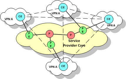
In a fully-meshed VPN, IP Service Activator tests the connection between each pair of sites, as shown in Figure 2-2.
Figure 2-2 Connection Tests in a Fully-Meshed VPN
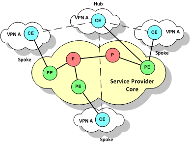
In a hub and spoke VPN, IP Service Activator tests the connection between the hub site and each spoke site, as shown in Figure 2-3.
Figure 2-3 Connection Tests in a Hub and Spoke VPN
If there are multiple hub sites and they are meshed, IP Service Activator also tests the connection between each pair of hub sites.
When you apply SAA to a VPN, you can specify whether the probe configured for each pair of sites is:
A one-way (half duplex): an operation is configured on only one device in the connection
A two-way (full duplex): an operation is configured on both devices in the connection
For TCP Connect, UDP Echo and Jitter operations, IP Service Activator also configures SAA Responder on target devices probed by one of these operations.
For a one-way probe, IP Service Activator configures the operation on only one device for each A to B pair.
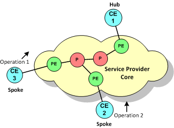
For hub and spoke VPNs, a probe is configured on each spoke, testing the connection from the spoke to the hub. These probes are shown in Figure 2-4.
Figure 2-4 One-way Probes in a Hub and Spoke VPN
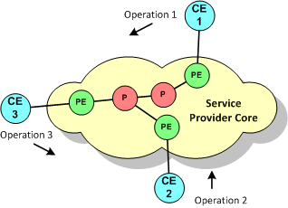
For fully-meshed VPNs, IP Service Activator chooses one of the devices in each pair and configures the probe on that device only, ensuring that the load imposed by SAA is evenly distributed between devices. These probes are shown in Figure 2-5
Figure 2-5 One-way Probes in a Fully-Meshed VPN
For a two-way probe, IP Service Activator configures the operation on both devices for each A to B pair.
For hub and spoke VPNs, an operation is configured on each spoke, with the hub as the target, and on the hub an operation is configured to probe each spoke connection. These operations are shown in Figure 2-6.
Figure 2-6 Two-way Probes in a Hub and Spoke VPN
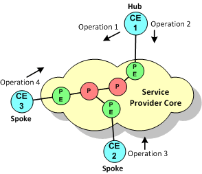
If there are multiple hub sites and they are meshed, IP Service Activator probes the connection between each pair of hub sites.
For fully-meshed VPNs, probes are performed between each pair of sites. These probes are show in Figure 2-7.
Figure 2-7 Two-way Probes in a Fully-Meshed VPN
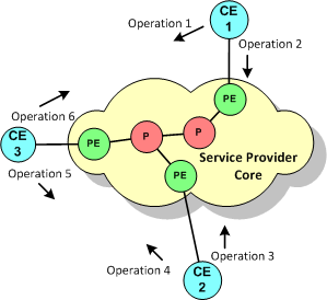
An unmanaged device is a device that is not managed by IP Service Activator. It is possible to test the connection from a managed device to an unmanaged device by modelling the unmanaged device as a virtual router. The virtual device is set up as the destination device in a one-way probe. One or more managed devices can then send test packets to the virtual device.
For information on modelling a virtual device, see IP Service Activator User's Guide.
Note:
When testing the connection to a virtual device, Jitter, UDP Echo and TCP Connect operations require the manual configuration of rtr responder on the target device. IP Service Activator cannot configure rtr responder on an unmanaged (virtual) device.The connection to a virtual device can be tested in one direction only; that is, from the managed to the unmanaged device.
Table 2-1 summarizes IP Service Activator's support for SAA operations.
Table 2-1 Supported SAA Operations
| Operation | Description |
|---|---|
|
ICMP Echo |
Measures end-to-end response time between a Cisco router and devices using IP. |
|
UDP Echo |
Calculates UDP response times between a Cisco router and an IP-enabled device. |
|
TCP Connect |
Discovers the time it takes to connect to a target device. |
|
Jitter |
A super set of the UDP Echo operation. The Jitter operation additionally measures per-direction packet-loss and jitter (inter-packet delay variance). |
For detailed information about these operations, consult the Cisco documentation.
Note:
The number of SAA operations that can be configured on a Cisco device is limited by the router's IOS and hardware specification. Devices running IOS 12.1 or later support a maximum of 500 operations.For UDP Echo, ICMP and Jitter operations, the target device may not natively provide the service. You can specify whether the operation sends a control message to the target device to enable the destination port prior to sending a packet.
When you push ICMP probe to the device IP Service Activator doesn't activate RTR responder on the device. In this case, you must manually activate the RTR responder on the device.
For all operations, you can define the rising or falling threshold for response times to the operation's test packets. A variety of algorithms are available for calculating a violation. You can also specify how long the operation waits for a response, whether error checking is performed and whether loss of connection is reported for connection-oriented protocols. You can specify what happens when a threshold is violated or a timeout or error condition occurs, either sending an SNMP trap or an SNA NMVT alert. An SNA NMVT alert is an SNA message that conveys network management specific information.
Note:
IP Service Activator does not configure the target address for an SNMP trap or SNA NMVT alert. If you wish to send an SNMP trap or SNA NMVT alert, you must manually configure the target address details on the relevant devices.If you are generating reports using InfoVista, note that InfoVista does not respond to SNMP traps sent as a result of a violated threshold, timeout or loss of connection.
UDP Echo, Jitter and TCP Connect operations use non-native services to test the connection to a target device. The SAA Responder enables a router to respond to these operation types and must be configured on target devices. IP Service Activator automatically configures an SAA Responder on the relevant devices.
In IP Service Activator, an SAA template acts as a container for one or more SAA operations. A template may contain configuration details for different operation types, such as UDP and Jitter, or TCP Connect and Jitter. Once defined, a template can be applied to any number of VPNs.
For information on the limits that operate when defining an SAA template and applying SAA to a VPN, see "Creating an SAA Template".
IP Service Activator can apply SAA measurements to both MPLS and measurement-only VPNs.
When you apply SAA to a VPN, IP Service Activator configures operations between pairs of devices within the VPN. The number of operations configured depends on the VPN's topology and whether connections are tested in one or both directions. For more information, refer to the "Configuration Considerations".
Applying SAA to an MPLS VPN is suitable only where the VPN has a small number of sites or has a hub and spoke topology. If the VPN topology is fully-meshed, IP Service Activator configures a full mesh of SAA operations. The number of operations configured on each device will therefore be one less than the number of sites in the VPN.
SAA is processor intensive and significantly affects device performance. The greater the number of sites in the VPN, the greater the number of operations configured on each device.
If you choose to deploy more than one SAA operation, for example, Jitter and TCP Connect, operations are configured for each type.
A measurement-only VPN allows you to apply SAA to a subset of devices in an MPLS VPN or to apply SAA without configuring an MPLS VPN. A measurement-only VPN can be used to:
Group a subset of devices that belong to an MPLS VPN and apply SAA to those devices.
This enables you to measure the connection between selected devices in an MPLS VPN, where the size of the VPN or its topology makes measuring all connections unfeasible.
Figure 2-8 illustrates this idea. All CE devices are members of an MPLS VPN. To reduce the number of operations configured, however, only the connection between CE1 and CE2 is measured. This is achieved by overlaying the MPLS VPN with a measurement-only VPN and applying SAA to the measurement-only VPN.
Group devices that do not participate in an MPLS VPN and apply SAA measurement.
This enables you to measure a connection between any pair of devices without the need to configure MPLS.
SAA Measurement is configured in IP Service Activator by defining an SAA template that holds one or more SAA operations and applying the template to a VPN.
This section covers the following topics:
For more information on the Service Assurance Agent, refer to the Cisco documentation.
Before configuring SAA in IP Service Activator, ensure that the following pre-requisites are implemented:
The RTT-MON MIB v2.1.0 or later must be present on the devices that you want to configure an SAA operation.
Given that memory problems are common, the following command should be run on CE devices before configuring the SAA probes:
Global config mode
rtr low-memory #
Where # is an integer that is equal to 25% of the memory available in the system. For more information, refer to the Cisco documentation.
If you intend to generate reports based on the SAA measurement, there may be additional pre-requisites associated with the reporting tool. For more information about the reporting tool's measurement requirements, see one of the following chapters, depending on which reporting tool you intend to use: Generic Exporter, InfoVista Integration, or Micromuse Integration.
This section highlights some of the deployment considerations associated with applying SAA using IP Service Activator.
Check the device's capabilities to determine which operation types are supported. The operation types can be found on the device object's Properties page in the Capabilities section, as shown in Figure 2-9.
Make sure that you specify the correct device roles when defining data collection points. For more information, see "Creating Collectors".
Ensure that you apply SAA templates only to the VPNs that you want to measure.
SAA measurement can be set up for the following VPN connections:
Configuring SAA for a PE to PE Connection using Shadow Routers
Configuring SAA for a PE to CE Connection using a Shadow Router
You can also test the connection to an unmanaged device by modelling it as a virtual router. For more information, see "Unmanaged Devices".
A shadow router is a device dedicated to SAA measurements in a service provider's Points of Presence (POP). Deploying shadow routers enables realistic PE to PE or PE to CE metrics to be gathered and protects measurement routers from customers. A PE device may have any number of shadow routers attached to it.
When configuring SAA measurements for different VPN connections, you may need to refer to the following additional references:
For information on setting up a VPN, see IP Service Activator VPN User's Guide.
Refer to the section "Configuring SAA Measurement in IP Service Activator" for procedures on how to:
Create an SAA template and apply it to a VPN.
Create a measurement-only VPN.
By deploying SAA on CE devices (or Virtual CEs), as shown in Figure 2-10, you can capture information about the complete end-to-end performance of a VPN service.
You can only test a CE to CE connection where one or both CE devices are managed. An unmanaged device may be modelled as a virtual router and a one-way test performed. See "Unmanaged Devices".
There are two alternatives for monitoring a CE to CE connection:
Apply SAA to the MPLS VPN: this setup is feasible only in some scenarios. See "Configuration Considerations" and "MPLS VPN".
Overlap an MPLS VPN with a measurement-only VPN populated by a subset of the CE devices and apply SAA to the measurement-only VPN
To apply SAA to a CE to CE connection in an MPLS VPN:
Create a Management VPN populated by the CE devices and the management station.
Create an MPLS VPN where each site consists of a CE device and a PE interface.
Apply an SAA template to the MPLS VPN.
To apply SAA to a CE to CE connection in a measurement-only VPN:
Create a Management VPN populated by the CE devices and the management station.
Create an MPLS VPN where each site consists of a CE device and a PE interface.
Create a measurement-only VPN, populated by a subset of the MPLS VPN's CE devices.
You do not need to associate the PE interface with the measurement-only VPN's sites.
Apply an SAA template to the measurement-only VPN.
For information about setting up a VPN, see IP Service Activator VPN User's Guide.
For information about creating and applying an SAA template and creating a measurement only VPN, see "Configuring SAA Measurement in IP Service Activator".
PE to PE measurement provides information about the performance across the network backbone.
If you wish to collect PE to PE metrics, you must deploy shadow routers.
In IP Service Activator, a shadow router behaves in a similar way to a CE device: it may be associated with a site and have a VRF table associated with it, a protocol may be specified for connection to the PE device, and so on.
IP Service Activator includes a system-defined Shadow role which must be assigned to the shadow devices. For information on assigning a role to a device, see IP Service Activator User's Guide.
Figure 2-11 SAA for PE to PE Connections using Shadow Routers
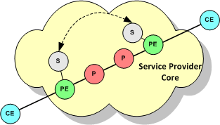
The PE device to which a shadow router is attached may participate in more than one MPLS VPN, where each VPN belongs to a different customer. If you wish to view performance metrics per customer in IP Service Activator using an integrated reporting tool, you must create a measurement-only VPN for each customer. Populate the measurement-only VPN with the relevant shadow routers and apply SAA to the VPN.
To apply SAA to a PE to PE connection using shadow routers:
Create a Management VPN populated by the shadow routers and the management station.
Create an MPLS VPN where each site is a shadow router and a PE interface.
If you wish to group a subset of shadow routers by customer, create a measurement-only VPN populated by the relevant shadow routers.
Apply an SAA template to the MPLS VPN and, if created, each measurement-only VPN.
For information about setting up a VPN, see IP Service Activator VPN User's Guide.
For information about creating and applying an SAA template and creating a measurement only VPN, see "Configuring SAA Measurement in IP Service Activator".
PE-CE metrics provide information about the connection between the service provider's POP and a customer site. A shadow router must be deployed at the PE device, as shown in Figure 2-12.
Figure 2-12 SAA for PE to CE Connections using a Shadow Router
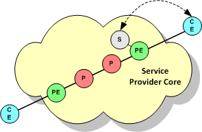
If the CE device is not managed it is possible to test the connection to it by modelling the device as a virtual router. See "Unmanaged Devices".
To apply SAA to a PE to CE connection using a shadow router:
Create a Management VPN that contains the shadow routers and the management station and, optionally, the CE devices.
Alternatively, you can create two Management VPNs: one for the shadow routers and one for the CE devices.
Create an MPLS VPN where each site is a CE device and a PE interface.
Create a measurement-only VPN populated by a shadow router attached to one of the MPLS VPN's PE devices and one or more of the CE devices attached to the PE device.
Apply an SAA template to the measurement-only VPN.
For information about setting up a VPN, see IP Service Activator VPN User's Guide.
For information about creating and applying an SAA template and creating a measurement only VPN, see "Configuring SAA Measurement in IP Service Activator".
This section covers the following procedures:
By default, an SAA template has:
A maximum of 1024 devices may participate in the VPN
A maximum of 4 Type of Service (ToS) values may be used within the VPN
A maximum of 4 operation types may be applied to the VPN
However, you can adjust these VPN-specific limits by specifying the amount of space that IP Service Activator allocates to store device, ToS value or operation type data.
Figure 2-13 Adjusting the SAA Template Values
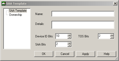
By adjusting the values of Device ID Bits, TOS Bits, and SAA Bits, you can increase the number of devices within the VPN, the number of operations, or the number of operation types that can be applied. The values specified for these three fields must add up to exactly 14. If you choose to increase the number of bits allocated to the device ID, you must reduce either the number of bits allocated to the ToS value or the SAA operation type.
If you wish to apply more than one operation to a single peer-to-peer connection in a VPN, you must ensure that either the ToS value or the operation type differs between the operations. This is because IP Service Activator bases each operation's unique RTR (Round Time Response) number on the ToS value and operation type (in combination with other types).
To create an SAA template:
On the System tab, right-click on the SAA Templates folder.
Select Add SAA Template from the context menu.
The SAA Template dialog box opens.
Specify values including Name, Details, Device ID Bits, TOS Bits, and SAA Bits.
Click OK and commit the transaction.
You can only configure SAA operations to test the connection between two devices that are in the same customer VPNs.
To add an SAA operation to a template:
On the System tab, open the SAA Templates folder.
Right-click on the SAA template and select Add SAA Operation from the context menu.
The SAA Operation dialog box appears.
On the SAA Operation property page, specify values including Type, Source port, Destination Port, Request size, ToS, Control, Packets in sequence, Inter-packet interval, History lives kept, History filter, History buckets, and Tag Value.
Select the Threshold property page.
Specify values including Type, Rising, Falling, Repetitions, X, Y, Average, and Action.
Select the Other property page.
Specify values including Period, Timeout, Lifetime, Half duplex, Full duplex, Error checking, Connect checking, and Timeout checking.
You can use SAA to measure the point-to-point connection between any pair of devices without configuring an MPLS VPN.
To apply SAA without configuring an MPLS VNP:
Apply the appropriate roles to the relevant devices.
You can associate devices tagged with the Access or Shadow role with sites in a VPN.
Associate each device with a site. For Virtual CE measurements, you also associate the Virtual CE to the site.
You do not need to associate an interface with the site.
If needed, specify the device's (or Virtual CE's) SAA destination and source measurement address as follows:
Open the Device/Virtual CE dialog box.
Select the SAA property page. Note that attributes on the Virtual CE SAA property page are different than those on the Device SAA property page.
Configure Measurement Probe Destination Address in one of two ways:
Select Use device management address to use the device management IP address set up on the Device property page as the SAA destination measurement address.
Select Use and from the drop down list and choose one of the interfaces previously discovered on the device.
Configure Measurement Probe Source Address in one of four ways:
Select Use Measurement Probe Destination Address to use the Measurement Probe Destination Address as the Measurement probe source address in the device.
Select Use Device Management Address to use the Device Management Address as the Measurement probe source address in the device.
Select Use and from the drop-down menu select an address from the other available addresses in the device as the Measurement probe source address.
Select Not configured to avoid configuring the Measurement probe source address in the device.
Select Use and select an IP address from the drop-down list of interfaces that have previously been discovered by the device.
For each site:
Right-click on the site and select Properties from the context menu to open the Site dialog box.
Select the Connectivity property page.
In the Routing Type field, select None.
Create a VPN by right-clicking on the VPN folder and selecting Add MPLS VPN from the context menu.
Ensure that the Use MPLS option on the VPN property page of the VPN dialog box is cleared to effectively create a measurement-only VPN.
Add the relevant sites to the VPN.
To apply an SAA template to a VPN:
On the Service tab, select the relevant VPN and select Properties from the VPN's context menu.
VPNs are listed in the VPNs folder beneath the relevant customer.
Select the Measurement property page.
In the SAA Measurement field, select an SAA template from the drop-down list.
If a site is a member of more than one VPN to which SAA measurement is applied, there may potentially be one operation per VPN configured on the device, depending on the VPN's topology and whether one or two-way tests are performed. For information on the factors that affect the number of operations configured within a VPN, see "SAA Operations".