| Skip Navigation Links | |
| Exit Print View | |

|
Netra SPARC T5-1B Server Module HTML Document Collection |
Understanding the Server Module
Front and Rear Panel Components
Plan Communication With the Server Module During Installation
Prepare the Modular System and Server Module
Insert the Server Module Into the Chassis
Powering On the Server Module for the First Time
Powering On the Host for the First Time
Power On the Host Through the CMM (Web Interface)
Power On the Host Through the CMM (CLI)
Power On the Host Through the Front Panel (CLI)
Power On the Host Through the CMM SER MGT Port (CLI)
Oracle Solaris Configuration Parameters
Reach a State to Install a Fresh OS (Oracle ILOM Web Interface)
Reach a State to Install a Fresh OS (Oracle ILOM CLI)
For setup, testing, or service purposes, you can connect cables directly to the server module SP by first attaching a dongle cable to the UCP on the front panel of the server module.
 | Caution - Dongle cables should be removed when not in use. These cables have not been evaluated for electromagnetic compatibility compliance and are not to be used during normal system operation. |
There are two types of dongle cables you can use:
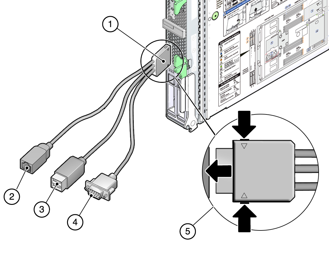
UCP-3 – Three-connector dongle cable (preferred) ships with the server module. Use the RJ-45 connector to connect to the server module SP.
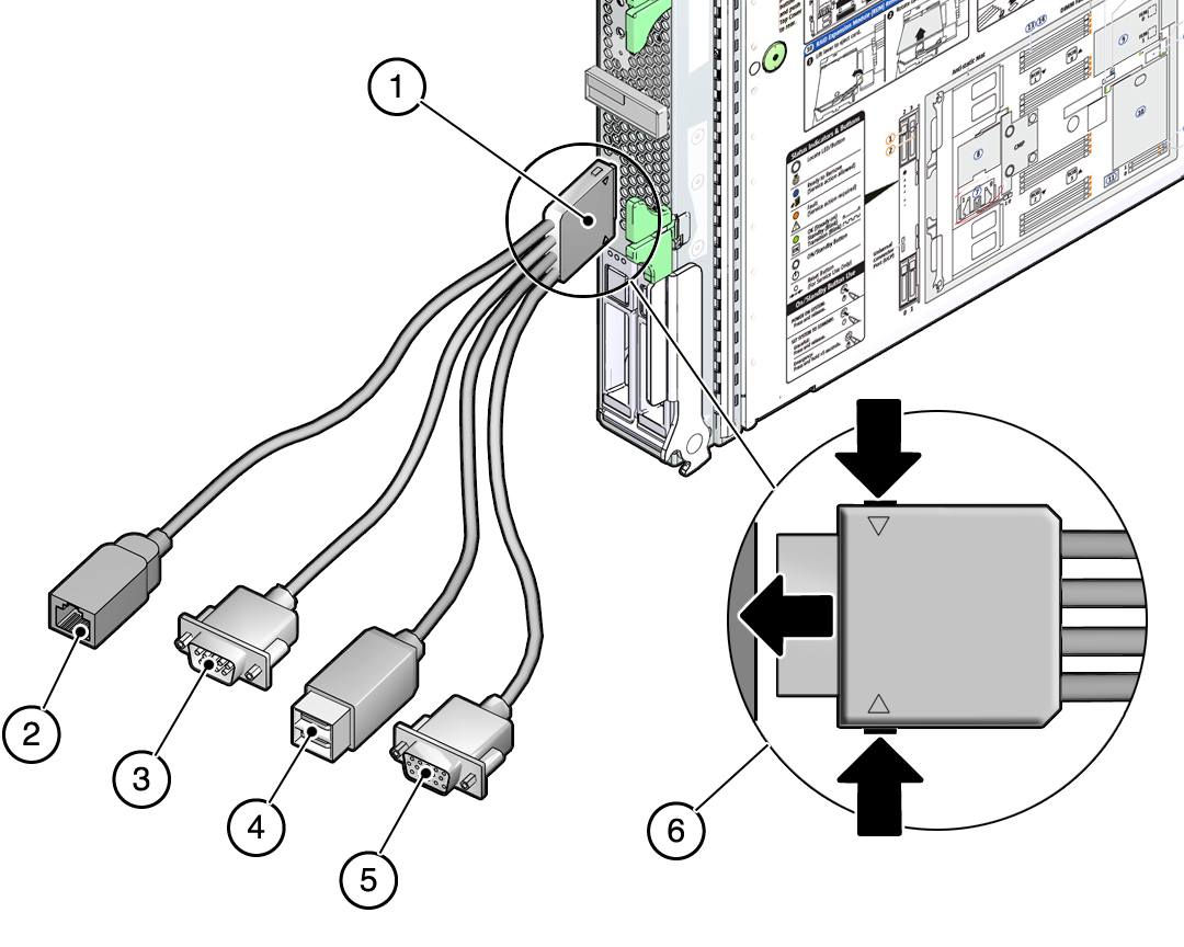
UCP-4 – Four-connector dongle cable (previous version). You must use the DB-9 connector to connect to the server module SP. The RJ-45 connector is not supported. If you need an RJ-45 connection, attach an optional DB-9-to-RJ-45 adapter to the DB-9 connector.
Figure 2-1 UCP-3 Three-Connector Dongle Cable

Figure Legend
1 Dongle connector attaching to the server module UCP
2 RJ-45 serial connector
3 USB 2.0 (two connectors)
4 VGA 15-pin female connector
5 Insertion and release buttons
Figure 2-2 UCP-4 Four-Connector Dongle Cable

Figure Legend
1 Dongle connector attaching to the server module UCP
2 RJ-45 serial connector (Do not use this connector on the UCP-4)
3 DB-9 serial male connector (TTYA)
4 USB 2.0 (two connectors)
5 VGA 15-pin female connector
6 Insertion and release buttons