6to4 Tunnels
Oracle Solaris includes 6to4 tunnels as an interim method for making the transition from IPv4 to IPv6 addressing. 6to4 tunnels enable isolated IPv6 sites to communicate across an automatic tunnel over an IPv4 network that does not support IPv6. To use 6to4 tunnels, you must first configure a boundary router on your IPv6 network as one endpoint of the 6to4 automatic tunnel. Thereafter, the 6to4 router can participate in a tunnel to another 6to4 site or to a native IPv6 non-6to4 site, if required.
Topology of a 6to4 Tunnel
A 6to4 tunnel provides IPv6 connectivity to all 6to4 sites everywhere. Likewise, the tunnel also functions as a link to all IPv6 sites, including the native IPv6 internet, provided that the tunnel is configured to forward to a relay router. The following figure shows how a 6to4 tunnel provides this connectivity between 6to4 sites.
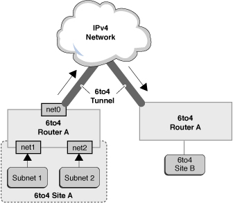
Figure 4-2 Tunnel Between Two 6to4 Sites

The previous figure depicts two isolated 6to4 networks, Site A and Site B. Each site has configured a router with an external connection to an IPv4 network. A 6to4 tunnel across the IPv4 network provides a connection to link 6to4 sites.
Before an IPv6 site can become a 6to4 site, you must configure at least one router interface for 6to4 support. This interface must provide the external connection to the IPv4 network. In the previous figure, boundary Router A's interface net0 connects Site A to the IPv4 network. The address that you configure on net0 must be globally unique. You must configure the net0 interface with an IPv4 address before you can configure a tunnel interface for 6to4 support on the router.
In the figure, 6to4 Site A is composed of two subnets that are connected to interfaces net1 and net2 on Router A. All IPv6 hosts on either subnet of Site A are automatically reconfigured with 6to4-derived addresses upon receipt of the advertisement from Router A.
Site B is another isolated 6to4 site. To correctly receive traffic from Site A, a boundary router on Site B must be configured for 6to4 support. Otherwise, packets that the router receives from Site A are not recognized and are then dropped.
6to4relay Command
6to4 tunneling enables communication between isolated 6to4 sites. However, to transfer packets with a native, non-6to4 IPv6 site, the 6to4 router must establish a tunnel with a 6to4 relay router. The 6to4 relay router then forwards the 6to4 packets to the IPv6 network and ultimately, to the native IPv6 site. If your 6to4-enabled site must exchange data with a native IPv6 site, you use the 6to4relay command to enable the appropriate tunnel.
Note - Because the use of relay routers is insecure, tunneling to a relay router is disabled by default in Oracle Solaris. Carefully consider the issues that are involved in creating a tunnel to a 6to4 relay router before deploying this scenario. For detailed information, see Considerations for Enabling Tunnels to a 6to4 Relay Router. If you decide to enable 6to4 relay router support, you can find the related procedures in How to Create and Configure an IP Tunnel.
For more information, see the 6to4 (7M) man page.
Packet Flow Through the 6to4 Tunnel
This section describes the flow of packets from a host at one 6to4 site to a host at a remote 6to4 site. This scenario uses the topology that is shown in Figure 4–2. Moreover, the scenario assumes that the 6to4 routers and the 6to4 hosts are already configured.
The packet flow is as follows:
-
A host on Subnet 1 of 6to4 Site A sends a transmission with a host at 6to4 Site B as the destination. Each packet header has a 6to4-derived source address and 6to4-derived destination address.
-
Site A's router encapsulates each 6to4 packet within an IPv4 header. In this process, the router sets the IPv4 destination address of the encapsulating header to Site B's router address. For each IPv6 packet that flows through the tunnel interface, the packet's IPv6 destination address also contains the IPv4 destination address. Thus, the router is able to determine the IPv4 destination address that is set on the encapsulating header. Then, the router uses standard IPv4 routing procedures to forward the packet over the IPv4 network.
-
Any IPv4 routers that the packets encounter use the packets' IPv4 destination address for forwarding. This address is the globally unique IPv4 address of the interface on Router B, which also serves as the 6to4 pseudo-interface.
-
Packets from Site A arrive at Router B, which decapsulates the IPv6 packets from the IPv4 header.
-
Router B then uses the destination address in the IPv6 packet to forward the packets to the recipient host at Site B.
Considerations for Enabling Tunnels to a 6to4 Relay Router
6to4 relay routers function as endpoints for tunnels from 6to4 routers that need to communicate with native IPv6, non-6to4 networks. Relay routers are essentially bridges between the 6to4 site and native IPv6 sites. Because this solution might be insecure, by default, Oracle Solaris does not enable 6to4 relay router support. However, if your site requires such a tunnel, you can use the 6to4relay command to enable tunneling, as depicted in the following figure.
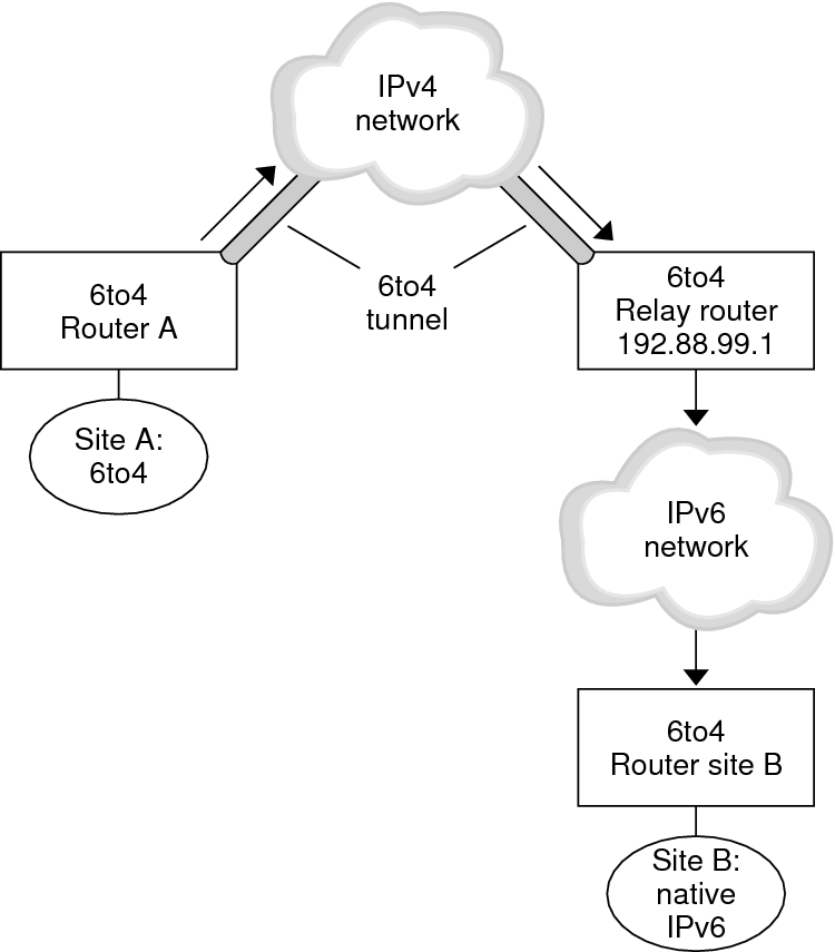
Figure 4-3 Tunnel From a 6to4 Site to a 6to4 Relay Router

In Figure 4–3, 6to4 Site A needs to communicate with a node at the native IPv6 Site B. The figure shows the path of traffic from Site A onto a 6to4 tunnel over an IPv4 network. The tunnel has 6to4 Router A and a 6to4 relay router as its endpoints. Beyond the 6to4 relay router is the IPv6 network, to which IPv6 Site B is connected.
Packet Flow Between a 6to4 Site and a Native IPv6 Site
This section describes the flow of packets from a 6to4 site to a native IPv6 site. This scenario uses the topology that is shown in Figure 4–3.
The packet flow is as follows:
-
A host on 6to4 Site A sends a transmission that specifies as the destination a host at native IPv6 Site B. Each packet header has a 6to4-derived address as its source address. The destination address is a standard IPv6 address.
-
Site A's 6to4 router encapsulates each packet within an IPv4 header, which has the IPv4 address of the 6to4 relay router as its destination. The 6to4 router uses standard IPv4 routing procedures to forward the packet over the IPv4 network. Any IPv4 routers that the packets encounter forward the packets to the 6to4 relay router.
-
The physically closest anycast 6to4 relay router to Site A retrieves the packets that are destined for the 192.88.99.1 anycast group.
Note - 6to4 relay routers that are part of the 6to4 relay router anycast group have the IP address 192.88.99.1. This anycast address is the default address for 6to4 relay routers. If you need to use a specific 6to4 relay router, you can override the default and specify that router's IPv4 address. -
The relay router decapsulates the IPv4 header from the 6to4 packets, revealing the native IPv6 destination address.
-
The relay router then sends the now IPv6-only packets onto the IPv6 network, where the packets are ultimately retrieved by a router at Site B. The router then forwards the packets to the destination IPv6 node.