| Skip Navigation Links | |
| Exit Print View | |

|
Sun Blade X4-2B Service Manual |
Troubleshooting the Server Module
Servicing Server Module Components
Returning the Server Module to Operation
Return the Server Module to Operation
Install the Server Module Top Cover
Remove Server Module Filler Panel
Power On Using the Power Button
Power On (Oracle ILOM SP Web Interface)
BIOS Power-On Self-Test (POST) Checkpoints
Caution - Component damage or personal injury. Blades can weigh up to 22 lbs (10kg). Use two hands to install or remove the blade from the chassis. |
Caution - Over-temperature condition. Do not operate the chassis with empty slots. Always insert a server module filler panel into an empty slot within 60 seconds to reduce the possibility of server module shutdown due to overheating. |
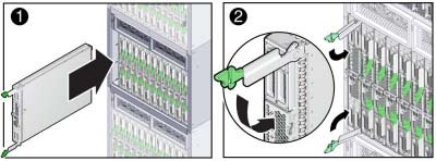
Pull the lever handle out and eject the server module filler panel.
Retain the server module filler panel.
To unlock the handles, squeeze the green color lock releases on the end of the handles. Rotate the handles outward, away from the front of the server module.

Rotating the levers draws the server module into the chassis and engages the connector on the server with the internal connector on the chassis mid plane. The server module is now flush with the chassis, and the ejectors are locked.
If the chassis has power, the server module SP boots and the server powers on to standby power state. The green OK indicator on the front panel blinks (0.2 seconds on, 2.8 seconds off).
Next Steps