JavaScript is required to for searching.
Skip Navigation Links
Exit Print View
Sun Blade X4-2B Service Manual
Oracle Technology Network
Library
PDF
Print View
Feedback
search filter icon
search icon

Document Information

Using This Documentation

Service Manual Overview

About the Sun Blade X4-2B

Product Description

About Front and Rear Panels

Front Panel Features

Front Panel Indicators and Buttons

Location of Front Panel Indicators and Buttons

Locate Indicator Button

Ready To Remove Indicator

Service Action Required Indicator

Power OK Indicator and Button

NMI Button

Rear Panel of the Server Module

UCP and the Multi-Port Dongle Cable

Attach the Multi-Port Dongle Cable

About the Chassis

The System Chassis

The Chassis Monitoring Module (CMM)

About Oracle ILOM

About System Components

Illustrated Parts Breakdown

Replaceable Components (FRUs and CRUs)

Component Serviceability

Troubleshooting the Server Module

Preparing for Service

Servicing Server Module Components

Returning the Server Module to Operation

BIOS Power-On Self-Test (POST) Checkpoints

BIOS Setup Utility Menu Options

Index

Front Panel Features

The following illustration shows front panel features on the Sun Blade X4-2B.
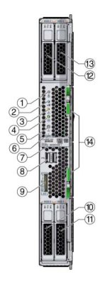
image:An illustration showing the server module system front panel.
Figure Legend
1
Locate Button and Indicator– white
8
USB ports (2)
2
Ready to Remove Indicator – blue
9
Universal connector port (UCP)
3
Service Action Required Indicator – amber
10
Storage drive (HDD 0)
4
Power OK Indicator – green
11
Storage drive (HDD 1)
5
Power button
12
Storage drive (HDD 2)
6
NMI Reset button (Service only)
13
Storage drive (HDD 3)
7
RFID tag (with serial number)
14
Ejector levers

See Also:

Front Panel Indicators and Buttons