7 Networks
The following information is included:
7.1 Introduction to Networks
Oracle Enterprise Manager Ops Center manages network resources, from the physical to the virtual. Fabrics provide the physical infrastructure and network domains provide the logical infrastructure. Networks are created from the resources of a network domain.
Oracle Enterprise Manager Ops Center supports Ethernet and InfiniBand network protocols. While the Ethernet interconnect is the established and common interconnect, InfiniBand is popular in high-performance computing environments because it maximizes the speed of transactions using the short, multiple connections found in clusters and data centers.
-
For an Ethernet network, both tagged and untagged VLANs are supported. An untagged VLAN has no VLAN IDs. Use tagged VLANs to create multiple networks on a fabric that use the same network address but different VLAN IDs. The network instances are independent of each other. However, in a server pool, use either all tagged VLANs or all untagged VLANs; do not mix the types of network in a server pool. For more information, see Mixed Network Tagging Mode Configurations in Server Pool.
Note:
Previous versions of the product software did not create independent network instances. -
For an InfiniBand network, partitions are supported.
Note:
If you use an InfiniBand switch in an Ethernet network, the ports on the switch have Ethernet names.7.2 Roles Required for Networks
Table 7-1 lists the tasks and the role required to complete the task. Contact your administrator if you do not have the necessary role or privilege to complete a task. See the Oracle Enterprise Manager Ops Center Administration Guide for information about the different roles and the permissions they grant.
7.3 Actions for a Networks
After a network is discovered or created, you can perform the following actions, depending on the requirements.
-
Discover and manage the switches
-
Add a fabric to network domain
7.4 Location of Network Information in the User Interface
Table 7-2 shows where to find information.
Table 7-2 Location of Network Information in the BUI
| Object | Location |
|---|---|
|
Fabric |
Expand Networks in the Assets pane. Then select Fabrics. |
|
Physical Fabric |
Expand Networks in the Assets pane. Then select Fabrics and select Network Switches. |
|
Network |
To see all networks, regardless of type, expand Networks in the Assets pane. Then select Network Domains. |
|
Services of a Network |
Network Services tab: time server, WINS, DNS, and NIS. To modify these services, edit the network services. You cannot change the network's IP address or name. |
|
Network Domain |
Expand Networks in the Assets tree. The Default Network Domain is the first item. |
|
Physical switch |
Expand Assets and expand Network Switches. To see each port, click the Connectivity tab. |
7.5 Fabrics
The fabric is the physical network infrastructure, such as switches, ports, host bus adapters, that provides network resources, through a network domain, to virtual assets.
When you use Oracle Enterprise Manager Ops Center to discover a physical switch or the host of switch, all the switching fabrics that the switch supports are also discovered. One physical fabric supports many fabrics, also called data links. The physical fabric is the collection of all switch ports, links, and physical interfaces or endpoints.
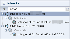
Description of the illustration fabric_pane.png
For each Ethernet fabric, the maximum VLAN ID range is 4096, which allows you to create 4096 networks.
For each InfiniBand physical fabric, the maximum number of partitions keys is 32000 so you can create 32000 partitions. Each partition is a logical fabric. For example, if a server has two partition keys, it participates in two different partitions.
Fabrics provide resources to the virtual networks they support in a manner that depends on their type: fully-managed, host-managed, or unmanaged. Table 7-3 shows the types of fabrics.
Table 7-3 Fabrics and the Network Domain
| na | What Is Managed | Capability | Comments |
|---|---|---|---|
|
The switch is discovered and managed. |
For each VLAN ID or partition key, you can create a static or dynamic private network. |
This type of fabric can be achieved on only the Sun Ethernet 10GbE Fabric switch or the Sun Datacenter InfiniBand switch and gateway. |
|
|
The host connected to the Ethernet switch is discovered and managed. A range of VLAN IDs has been assigned. |
For each VLAN ID, you can create a static or dynamic private network. |
To create a host-managed fabric, use the Define Ethernet Fabric action to specify the fabric and its VLAN ID range. |
|
|
The Ethernet fabric is discovered or declared during the discovery of another asset, but the switch is not managed. |
If the fabric has existing networks with VLAN IDs, you can create static private networks. |
To convert an unmanaged fabric to a host-managed fabric, use the Assign VLAN ID Range action. |
7.6 Network Domains
A network domain is a container for fabrics, managed networks, and private networks. The network domain handles the relationship between the physical fabrics and the virtual assets, such as virtualization hosts or server pools. The fabrics provide data links and IP subnets to the network domain, which then provides networks to the virtualization hosts and server pools.
Within the network domain, networks that have been discovered or specified are available for assignment. These are called public networks because their IP address space has been specified for their exclusive use. Another type of network is private, that is, the network is created using an IP address space that the network domain allocates to it.
A fabric can contribute to more than one network domain. When a network domain has more than one fabric, you designate one of the fabrics as the anchor fabric, which is the fabric from which new networks are created.
Public networks can be members of more than one network domain because their IP addresses are specific and dedicated. Private networks exist only within a specific network domain so two network domains could construct a private network with the same IP address without a conflict.
In Oracle Enterprise Manager Ops Center, networks become part of a network domain in the following ways:
-
An asset that has a network is discovered.
-
A user creates a network.
-
A network is created when it is required. This is a dynamic network.
Oracle Enterprise Manager Ops Center operates on more than one layer of the Open Systems Interconnection model, using the network domain. Table 7-4 shows what the network domain manages in the physical to logical stack.
Table 7-4 Elements of a Network Domain
| Layer | Asset | What Is Managed | Capability |
|---|---|---|---|
|
Layer 3 Network: IP address |
For Ethernet: fabric networks For InfiniBand: non-fabric networks |
IP subnet and mask IP address range VLAN or Partition Services Routing |
The network provides connectivity. |
|
Layer 2 Data links |
For a tagged Ethernet: VLAN For an untagged Ethernet: portID For InfiniBand: partition |
VLAN IDs Partition keys (P-key) |
A virtual host uses the virtual NIC and a virtual switch in a VLAN or partition. |
|
Layer 1 Physical: switches, ports, host bus adapters |
Fabrics |
Varies, by type of fabric. See Table 7-3 |
Varies by type of fabric. See Table 7-3 |
7.6.1 Default Network Domain
The Oracle Enterprise Manager Ops Center software always has a Default Network Domain and all networks are members of it. If you have upgraded your product software from the previous release, the existing managed networks are now in the Default Network Domain. A new network becomes a member of the default network domain. If you direct the new network to a user-defined network domain, the network is also a member of that network domain.
7.6.2 User-Defined Network Domains
Like the default network domain, a user-defined network domain provides network resources to a server pool or virtualization host. You create a network domain to support the use of virtualization hosts, server pools, or a virtual datacenter. For example, a virtual datacenter uses server, storage, and network resources in a dynamic way, allocating and releasing resources whenever necessary. The network domain provides the network resources to the virtual datacenter.
When you create a network domain, you set a limit on the number of networks that can be created in the network domain. Increase the number of networks when accounts in a virtual datacenter are not able to create vnets.
A new user-defined network domain includes the address space specified as private by the RFC 1918 specification. These addresses cannot be routed to the Internet and provide a way for organizations to create intranets. If you organization uses a portion of this private address space, reserve these IP addresses when you create a network domain so that the network domain does not use them.
7.6.3 Editing Attributes of a User-Defined Network Domain
You can change the name and description of the network domain and you can change the number of dynamic networks that are in use simultaneously.
To Edit Attributes of a Network Domain
-
Expand Networks in the Navigation pane.
-
Click the network domain.
-
Click Edit Attributes in the Actions pane.
The Details tab is displayed in the center pane. You can now change the Name Description, and Number of Networks fields.
-
Edit the name or description or increase the number of networks.
-
Click Save.
7.7 Networks
In Oracle Enterprise Manager Ops Center, networks are the discovered and managed IP subnets. Oracle Enterprise Manager Ops Center manages network resources for its virtualization hosts.
Note:
These networks are part of Oracle Enterprise Manager Ops Center's virtualization services. For a description of the networks that support the product, see Oracle Enterprise Manager Ops Center's Networks.Networks are associated with a single virtualization host or a server pool, which contain multiple virtualization hosts. When you assign a network to a server pool, the network is accessible to each virtualization hosts in the pool and every guest of each virtualization host.
You can use networks to do the following:
-
Manage individual virtualization hosts
-
Connect virtualization hosts to the Proxy Controller
-
Allow guests to communicate with each other or with the Internet
-
Connect remote JMX with the public API
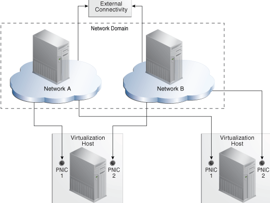
A network depends on the physical network interface card (PNIC) that is available to the host. You can create one network for each physical network interface card. If one host has two PNICs, it is a good practice to create two networks: a management network and a data network. Then place all virtual hosts on the data network, keeping them separate from the management network. The management network is dedicated to giving access to internal resources of the data center.
Figure 7-1 shows how two virtualization hosts participate in two networks. The actual network connection is made to the PNICs in the virtualization host. Network A is connected to PNIC 1 of both hosts and Network B is connected to PNIC 2 of the hosts.
7.7.1 Requirements for a Network
A network requires a physical network interface or a link aggregation and the following specifications:
-
IP address and netmask or CIDR format
-
If you use static IP addressing, the IP address of the management interface
If you use dynamic IP addressing, the range of allowed IP addresses and the gateway address
Before you attach a network to a server pool, verify that each virtualization host in the server pool has a physical network interface to the network so that all members of the pool can continue to share the network resources of the server pool.
7.7.2 Limitations of Networks
Ethernet networks and InfiniBand networks in the default configuration must not have the same CIDR (Classless Inter-Domain Routing) or with sub-blocks of the same CIDR. When discovering assets, verify that the Ethernet networks or InfiniBand networks in the default configuration comply with the following constraints. If so, reconfigure the asset before it is discovered.
-
No assets with overlapping management networks. For example, 192.0.2.1/21 and 192.0.2.1/24 are overlapping. However, you can use the same CIDR (not sub-block) for different assets. For example, you can use 192.0.2.1/22 as a CIDR for the Ethernet network for two assets.
-
No overlapping private networks. For example, two private networks cannot have the same CIDR.
-
No overlapping public networks. However, you can use the same CIDR (not sub-block) for different assets. For example, you can use 192.2.0.0/22 as a CIDR for the public EoIB network for multiple engineered systems.
For more examples of valid network specifications, see Example Oracle SuperCluster Network Configurations.
Starting in Release 12.2.2.0.0, you can configure InfiniBand networks to share a CIDR. However, when you allow networks to have the same CIDR, you must ensure that all the NFS shares used by storage libraries have a unique pathname. Oracle Enterprise Manager Ops Center identifies an NFS share by its CIDR, its NFS server, and the share name. When the CIDR addresses are the same, either each NFS server must have a unique name or each share must have a unique name. Use the following procedure to allow overlapping InfiniBand networks. You must have the Ops Center Admin role to change the value of a product property variable.
-
Log in to the Enterprise Controller.
-
Click Administration in the Navigation pane.
-
Click Enterprise Controller.
-
Click Configuration in the center pane.
-
In the Subsystem field, click Network/Fabric Manager. The
oem.oc.networkmgmt.ib.overlapping.enabledproperty's default value isfalse. -
Click in the Value field to edit it. Change the value to
true. -
Click the Save Properties icon.
-
Stop and restart the Enterprise Controller:
/opt/SUNWxvmoc/bin/ecadm stop
/opt/SUNWxvmoc/bin/ecadm start
7.7.3 Public Networks and Private Networks
Networks are introduced into Oracle Enterprise Manager Ops Center in the followings ways:
-
By discovering the fabric that supports existing networks. All the attributes are discovered but, other than the name and description, they cannot be changed. All networks of a discovered fabric are in the Default network domain.
-
By specifying the network completely, using the resources provided by a fabric. Use the Define Network action to specify the IP addresses and the VLAN IDs for an Ethernet network, based on what the fabric can provide. To create untagged networks, specify a VLAN ID of -1. For InfiniBand networks, the P-keys are assigned automatically.
Note:
In previous versions of the product software, this action was called Manage Network. -
The Create Private Network action creates a network from the resources of a user-defined network domain. Oracle Enterprise Manager Ops Center allocates the IP address from the addresses available within the network domain.
If you are creating networks for the use of virtual datacenters, create a private network to ensure that the virtual datacenter has exclusive use of the IP address space that it gets from the network domain. See Creating Private Networks in a Virtual Datacenter in the Operate How To library at http://docs.oracle.com/cd/E40871_01/nav/operatehowto.htm.
Note:
The Automated Installer for Oracle Solaris 11 uses theinstalladm service to identify all network interfaces and adds them to the /var/ai/ai-webserver/listen-addresses.conf file.
When you add a network interface, run the following command to update the installadm service and ensure the Automated Installer has access to all network interfaces:
svcadm refresh system/install/server
To see the list of network interfaces handled by the installadm service, view the /var/ai/ai-webserver/listen-addresses.conf file.
7.7.4 Assigning Networks to a User-Defined Network Domain
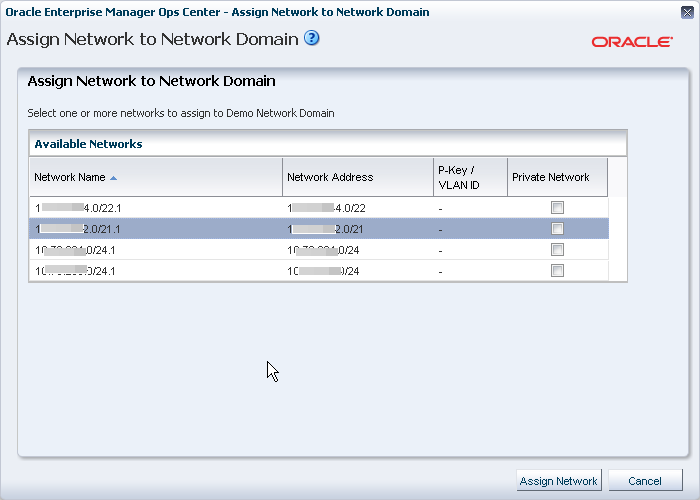
All networks are in the Default network domain, but a network can be a member of more than one user-defined network domains. You place a network into a user-defined network domain so that the network is available to the server pools associated with the network domain. Use the Assign Network action to place a network into a specific network domain.
-
Expand Networks in the Navigation pane.
-
Select the user-defined network domain.
-
Select Assign Network in the Actions pane.
-
Select a network. If the network is does not share its IP addresses with any other network, select the Private Network option.
-
Click Assign Network to submit the job.
7.7.5 Bandwidth Management
A data link is a physical NIC, an aggregated link, or a virtual NIC. When a new data link is created, the operating system sets the default bandwidth flow. You cannot remove this flow. The flow is removed only when the physical link is removed.
In Oracle Solaris 11 operating system environments, you can manage the bandwidth flow of a data link, prioritizing the network traffic on the link and setting the maximum bandwidth limit.
7.7.5.1 Managing the Bandwidth Flows for a Data Link
-
Select an Oracle Solaris 11 operating system.
-
Click the Networks tab in the center pane.
-
Click the Bandwidth Management subtab in the center pane.
-
To modify a flow, click the Modify icon. To create a new link, click the Add icon, then specify a name for the flow and the physical network interface.
The name of flow must meet the following requirements:
-
The first character must be alphabetic.
-
All characters must be alphanumeric: a-z, A-Z, 0-9, underscore ('_'), period ('.'), or hyphen ('-').
-
Maximum number of characters is 127.
-
-
Set the new bandwidth properties, as described in Properties of Bandwidth Flow.
7.7.5.2 Properties of Bandwidth Flow
-
Priority: Set the priority of the network traffic on the link as high, medium or low.
-
Bandwidth Limit: Enable the bandwidth limit to allocate guaranteed bandwidth to the specified link. Enter the maximum value for bandwidth limit in Kbps, Mbps, or Gbps.
-
Set attributes for the data flow to identify its network traffic:
-
Local and Remote IP: The source and destination IP address.
-
Transport: The Internet Protocol used such as TCP, UDP. SCTP, ICMP.
-
Ports: The source and destination ports for TCP, UDP, and SCTP.
-
DS Field: The type of service field in the IP packets' header.
-
7.7.6 Creating IPMP Groups
For information about how IPMP groups work in Oracle Solaris 11.2, see http://docs.oracle.com/cd/E36784_01/html/E37476/index.html. For information about how IPMP groups work in Oracle Solaris 11.1, see http://docs.oracle.com/cd/E26502_01/html/E28993/index.html. For Oracle Solaris 10 documentation, see IP Services at http://docs.oracle.com/cd/E26505_01/html/E27061/index.html.
From the Network tab, view and manage IPMP groups as shown in Figure 7-3.

For all types of networks, you create an IPMP group by specifying the following:
-
The link-based failure detection is enabled by default. To use, Probe-Based failure detection, select the Probe-Based option and provide the test address to track the interface status.
-
You must assign the data addresses for the physical interfaces in the IPMP group. Data traffic flow uses the data addresses hosted on the IPMP interface and flows through the active interfaces of the group.
-
The active and the standby interfaces of the group. By default, an interface added to an IPMP group is active. You can configure as many standby interfaces as you want for the group. The list of available network interfaces contains the interfaces that qualify, depending on the operating system, the type of network you select, and the network's existing attributes.
-
For an Ethernet network on Oracle Solaris 10:
-
If the network has a VLAN ID, you can select the Tagged mode and you can keep or change the VLAN ID.
-
If the network has a VLAN ID, you can select the Untagged mode and you can keep or change the VLAN ID.
-
If the network does not have a VLAN ID, the option to make it a tagged or untagged network is not available.
-
-
For an Ethernet network on Oracle Solaris 11, you can specify its media type:
-
For the Ethernet media type, the resulting options are the same as for an Ethernet network in the Oracle Solaris 10 environment.
-
For the InfiniBand media type for a network with a VLAN ID, the P-Key field is displayed.
-
-
For an InfiniBand network on Oracle Solaris 10, no network interfaces are included in the list of available network interfaces.
-
For an InfiniBand network on Oracle Solaris 11:
-
For the InfiniBand media type for a network with a VLAN ID, the P-Key field is displayed and you can keep or change its value.
-
For the Ethernet media type, the P-Key field is not available.
-
-
-
Click the Network tab in the center pane.
-
Click the IPMP Groups subtab in the pane. The existing IPMP groups are listed in the subtab.
-
Click the Create IPMP Group icon to open the Create IPMP Group wizard.
Figure 7-4 Specify IPMP Group Details for an Ethernet Network on Oracle Solaris 11
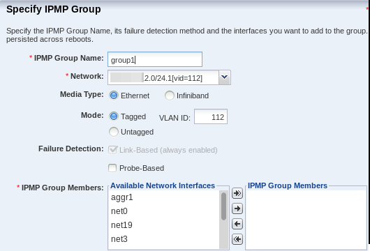
Description of "Figure 7-4 Specify IPMP Group Details for an Ethernet Network on Oracle Solaris 11"
Figure 7-5 Specify IPMP Group Details for an InfiniBand Network on Oracle Solaris 11
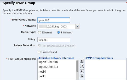
Description of "Figure 7-5 Specify IPMP Group Details for an InfiniBand Network on Oracle Solaris 11"
-
Enter the following details for the IPMP group, as shown in Figure 7-4:
-
Provide a name for the IPMP group.
-
Select a network from the list of available network interfaces.
-
Depending on the type of network you select, specify the characteristics of the network interfaces.
-
The Link-Based failure detection is always enabled by default. Select whether you want to also enable Probe-Based failure detection.
-
Select each interface you want in the IPMP group from the Available Network Interfaces list and click the right arrow to include the interface in the group.
Click Next to specify the NIC settings.
-
-
If you enabled probe-based failure detection, enter the test address for the NICs.
-
Select the interfaces that are in standby mode.
You must have at least one active interface in the group. Click Next.
-
Enter the data address for the active interfaces of the group and select whether the interface has a failover and click Next.
-
Review the information and click Finish to create the IPMP group.
7.7.7 Creating Link Aggregation
The link aggregation conforms to the Link Aggregation Control Protocol (LACP) as described in the IEEE 802.3ad Link Aggregation Standard specification. The switch that communicates with the network interface must also support LACP.
To create a link aggregation, specify the following:
-
Load balancing policy
-
Link Aggregation Control Policy (LACP) mode and timer
-
MAC address policy and if required, the MAC address
From the Network tab, you can create and manage the link aggregations as shown in Figure 7-6.

-
Click the Link Aggregation subtab.
-
Click the Create Link Aggregation icon to open the wizard.
-
Enter the name of the link aggregation. By default, the name starts with
aggrAppend a number to make the name unique. -
Select the network interfaces to be in the aggregation by selecting each one from the list of available interfaces and clicking the right arrow to include them in the list of network interfaces in the link aggregation. Click Next.
-
Specify the following information:
-
Policy for load balancing by setting the type of packet identification in outgoing traffic. Packets with the same identification ar e routed to the same network interface in a link aggregation. The L4 policy is the fastest and the default.
-
LACP mode, which is the type of LACPDU or packet required between the link aggregation and the switch. The value of
offrequires no packet, the value ofactivesends packets at intervals set by the LACP timer, and a value ofpassivesends a packet when the switch sends one. -
LACP timer, which sets the time for the LACP active mode. The default is 1 second.
-
MAC address policy is either Auto or Fixed. The Auto policy generates the MAC address. The Fixed policy uses the MAC address you enter.
Click Next to view the summary.
-
-
Review the information and click Finish to create the link aggregation.
7.8 Properties of a Network
7.8.1 IPv4 and IPv6 Protocols
Some environments have a mix of IPv4 and IPv6. Oracle Enterprise Manager Ops Center is "IPv6-aware." If an asset has an IPv6 network interface, Oracle Enterprise Manager Ops Center can read it and displays its information, but it cannot provision an IPv6 network or use IPv6 networks to discover, monitor, or provision assets.
7.8.2 Routing Mode
A virtual host uses the network assigned to it according to the host's routing mode. You specify a virtual host's routing mode during its initial configuration if you do not accept the default mode, Automatic Routing. Oracle Enterprise Manager Ops Center supports the following routing modes:
-
Automatic Routing – This is the default routing mode. Applying the static routes depends on the following conditions:
-
If your site defined a default gateway or static route or retrieved one from the DHCP server, this route is used and dynamic routing is disabled.
-
If no default gateway or static route is available, dynamic routing is enabled.
-
-
Dynamic Routing Off – The virtual host uses the default gateway and any static routes configured for the network. The default gateway is retrieved from the DHCP server.
-
Dynamic Routing On – The virtual host uses routes provided by the dynamic routing service. The default gateway and any static routes configured for the network are ignored.
7.8.3 Static Route for the Network
Static routes specify the route for external access. Although you define a default gateway for a network, it might not reach a particular subnet. In this case, you must also provide a static route for the subnet.
When you create a network, you can specify the static route. To add static routes after the network has been created, use the following procedure.
To Add a Static Route for the Network
-
Click Managed Networks in the Navigation pane.
-
Select a network from the list of networks.
-
Click Edit Network Attributes in the Actions pane.
-
Click the Add icon in the Static Routes table. A row is added to the table.
-
Enter the values for destination IP, netmask, and gateway.
-
Click Finish.
You can delete a static route and change the order of the routes using the icons in the Static Routes table.
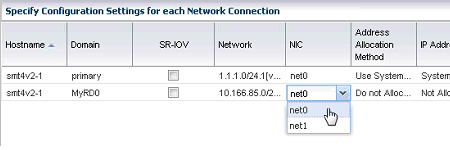
7.8.4 Address Allocation Method
When you define a new network, you specify how its IP address is assigned:
-
Static IP: You enter a specific IP address.
-
Use System Allocated IP: Oracle Enterprise Manager Ops Center assigns an available IP address.
-
Do not allocate IP: No IP address is assigned.
-
DHCP: Use the DHCP service to acquire an IP address.
When you create an Ethernet network without an SR-IOV connection for a control domain, you have an additional option: Do Not Plumb Interface.
7.8.5 Maximum Transmission Unit (MTU)
The default size for the network's Maximum Transmission Unit (MTU) is 1500 bytes. If your network interface card is one of the following types, you can change the size of the MTU to a size between 576 and 9216 bytes. However, to assign the network to a logical domain, the minimum MTU size is 1500 bytes.
-
e1000g -
ce -
nxge -
nge -
bge -
xge -
hme -
ixgbe -
hxge -
ipge -
igb
When you specify a size greater than 1500 bytes, Oracle Enterprise Manager Ops Center modifies the network interface card's MTU size. For other types of network interface cards, the MTU is changed when the card's driver firmware is updated to support the new MTU size. However, to change the MTU value for an IPMP group, you must edit the MTU value manually.
Note:
When you provision an operating system, the MTU size resets to the default value. You must change the MTU again after you provision the system.7.9 Network Utilization
Oracle Enterprise Manager Ops Center collects information every five minutes on every managed asset and displays the last hour of data on the asset. To see utilization data for a network over longer periods of time, up to six months, create a Network Utilization chart, which includes operating system, operating system for a virtual machine, virtual host, and server pool. You can also create a network utilization chart for an OS group or host group.
7.10 Network Connectivity
Connectivity is the network interface of the system. You can view information about a hardware asset's Network Interface Card (NIC) on the Connectivity tab of the asset's dashboard, including name, connection status, MAC address, and the corresponding IP address.
For switch hardware, the Connectivity tab shows information about each port.
For an Oracle Solaris OS, the Connectivity tab includes IPMP groups and aggregated links.
-
The IPMP Groups subtab shows the group's name, its assigned network, and the type of failure detection, either link-based, probe-based, or both. For each IPMP group, the details include the state of the connection for each NIC, whether it is in standby mode or failover mode, and the IP address the NIC supports.
-
The Link Aggregation subtab shows the aggregation's name, its MAC address, and its attributes. For each aggregated link, the subtab shows the state of the connection for each NIC, whether it is in standby mode or failover mode, and the IP address the NIC supports.
When you attach or assign networks or when you create virtual hosts, Figure 7-7 shows an example of a step in the wizard where you configure the network connection.
7.11 Network Hardware
Oracle Enterprise Manager Ops Center can manage Sun Ethernet 10GbE Fabric switches and Sun Datacenter InfiniBand switches. These switches reside in the system or blade system and provide the switch fabric.
The InfiniBand Gateway switch can expose the ports of a server that resides on an InfiniBand partition to an Ethernet network. To create an Ethernet on InfiniBand (EoIB) interface on the switch, you associate the switch's external port (eport) with the InfiniBand partition where the server resides, creating a virtual NIC (vNIC). The server's ports are displayed on the Switch Connectivity tab in the center pane.
For more information about these switches, see Switch Details or see Related Resources for Networks for links to the switch documentation.
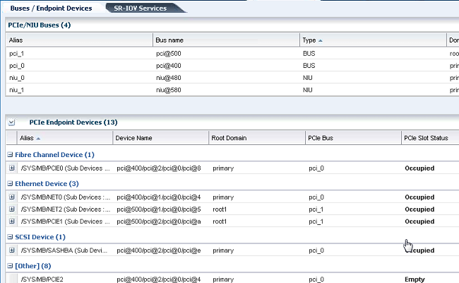
7.11.1 PCIe Endpoints
A PCIe bus consists of the PCIe bus itself and all of its PCI switches and devices. Oracle VM Server for SPARC software can assign a PCIe bus (also known as a root complex) to a domain. An I/O domain that is configured with an entire PCIe bus is also known as a root domain.
Oracle Enterprise Manager Ops Center also supports the NIU-compatible cards in T5x20, T3 or T4 systems if an XAUI card is present. You can assign the NIU device to a Logical Domain in the same way you assign a PCIe bus or End Point.
7.11.2 Single Root I/O Virtualization
InfiniBand switches support Single Root I/O Virtualization (SR-IOV), so that a single PCIe device (a physical network card) is presented as multiple PCIe devices. SR-IOV relies on both the hardware BIOS and the hypervisor layer to create these virtual PCIe devices. Each virtual PCIe device specializes in an operation called its virtual function (VF), but does not have the complete functionality of the physical PCIe device.
By defining a network on a virtual PCIe device, one physical PCIe device supports several networks as if each network had exclusive access to the device. Figure 7-9 shows the physical PCIe devices available to a virtualization host. When one of the physical functions is selected, its virtual functions are also displayed.
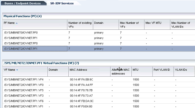
When you create a virtual host, you specify its network connection. If the networks are backed by an InfiniBand fabric, you can specify that the virtual host uses a virtual function by checking the SR-IOV option.
7.11.3 Network Interface Card (NIC)
The Network Interface Card (NIC) is the physical connection between a network switch and a network. When you create a network or attach an asset to a network, you select the NIC. You can create one network for each physical network interface card. To see the NICs for a server, select the server and then click the Connectivity tab. The Server Processor Connectivity table lists all of the NICs.
7.11.4 Network Switches
Oracle Enterprise Manager Ops Center can manage Sun Ethernet 10GbE Fabric switches and Sun Datacenter InfiniBand switches. These switches reside in the system or blade system and provide the switch fabric. The Cisco Catalyst® 4948 Switch is also supported.
For the Ethernet switches, both tagged and untagged VLANs are supported.
If you use an InfiniBand switch in an Ethernet network, the ports on the switch have Ethernet names.
For more information about these switches, see the product documentation:
-
For the Sun Ethernet 10GbE Fabric switch, see http://docs.oracle.com/cd/E19934-01/index.html
-
For the Sun Network QDR InfiniBand Gateway Switch, see http://docs.oracle.com/cd/E36256_01
-
For the Sun Datacenter InfiniBand Switch 36, see http://docs.oracle.com/cd/E26698_01
7.11.5 Virtual Network Switches
Oracle Solaris network virtualization provides an internal virtual network solution in which a virtualization host communicates with its virtual hosts as if using a network hardware. A virtual network consists of virtual network interface cards (VNICs) and virtual switches. A VNIC depends on a physical NIC and handles incoming and outgoing data in the same ways as a physical NIC. A virtual switch is created from the hypervisor layer of Oracle Solaris to provide the data path between the virtual hosts that reside on the same server and so must communicate with each other using the same ports. Figure 7-10 shows the relationship among the elements of a virtual network built on a single system with one NIC. Three VNICs support three zones. The virtual switch handles the communication, both between the VNICS and between the VNICs and the physical NIC.
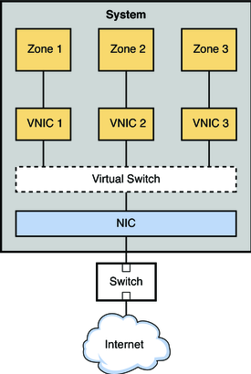
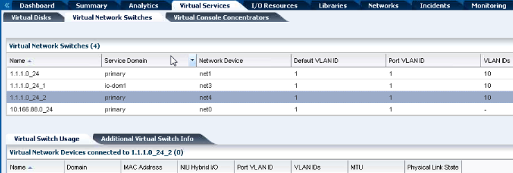
In Oracle Enterprise Manager Ops Center, the virtual network switches are listed on the Virtual Services tab, as shown in Figure 7-11. For a specific switch, you can also see VNICs that use the virtual switch.
7.12 Network Profiles
Oracle Enterprise Manager Ops Center provides default profiles for the following operations:
-
Monitor Network hardware – Reports Cisco switch's connection to assets on the Switch Connectivity tab.
-
Discover a switch – Use a discovery profile with Cisco iOS credentials.
7.13 Oracle Enterprise Manager Ops Center's Networks
This section describes the requirements for the networks that Oracle Enterprise Manager Ops Center uses. This section does not discuss the networks that support virtual hosts and server pools.
In the product environment, a unique network is a combination of an IP subnet address and a subnet mask. You can implement Oracle Enterprise Manager Ops Center's network connections using any combination of VLAN-tagged and untagged networks.
-
A network is considered VLAN-tagged when the interface is tagged at the Operating System. This is host-based tagging and the interface on the switch is the trunked interface.
-
A network is considered untagged when the interface is untagged at the Operating System. This is port-based tagging because VLAN tagging is configured at the switch.
7.13.1 Network Switch Configuration
Use these guidelines to configure a network switch for a system running the Oracle Enterprise Manager Ops Center software.
-
Use an Virtual LAN (VLAN)-capable switch.
-
Discover and manage the switch. Provide the credentials to log in to the switch management controller's
ilom-adminaccount. Do not use therootaccount.
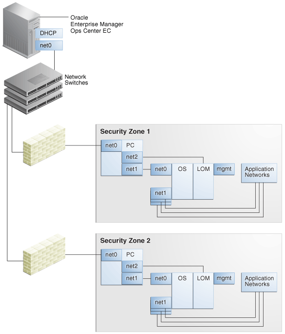
7.13.2 Separate Networks for LOM Management, Enterprise Manager Ops Center, and Applications
Create a separate VLAN for asset management and provisioning networks, as shown in Figure 7-14. For Ethernet connectivity:
-
The network used for managing a server's LOM must be a 10/100 MB connection to the server's net MGMT port. This is a requirement of the physical server.
-
The network used for managing a server's LOM must be a 10/100 MB connection to the server's net MGMT port. This is a requirement of the physical server.
7.13.3 DHCP Servers on Proxy Controllers
Each Proxy Controller has a DHCP server process that is used for OS provisioning. This DHCP server process does not provide general DHCP services. Instead, this DHCP server responds to requests only from the specific MAC address of the asset that is being provisioned and only for the duration of the provisioning job. When OS provisioning an asset on a network that is not connected directly to the Proxy Controller, you must enable DHCP Forwarding on each intermediate network switch.
7.13.4 Types of Network Configurations for Oracle Enterprise Manager Ops Center
7.13.4.1 Simplest Configuration: Test System
Figure 7-12 shows a minimal configuration:
-
Enterprise Controller (EC)
-
Co-located Proxy Controller (PC), that is, the PC runs on the same system as the Enterprise Controller.
-
Network connection (net0) can be a physical NIC, a link aggregate, or an IPMP group.
Figure 7-12 Configuration of a Test System

Description of "Figure 7-12 Configuration of a Test System"
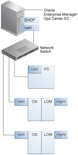
7.13.4.2 Simple Configuration: Datacenter on Same Network
Figure 7-13 shows a common configuration:
-
Enterprise Controller (EC)
-
Remote Proxy Controller (PC), that is, one or more Proxy Controllers running on different systems.
-
Network connection (net0) can be a physical NIC, a link aggregate, or an IPMP group.
Figure 7-13 Configuration Using One Network
Description of "Figure 7-13 Configuration Using One Network"
7.13.4.3 Good Practice: Separated Networks and Security
Figure 7-14 shows the preferred configuration:
-
Enterprise Controller (EC)
-
Remote Proxy Controllers (PC) in security zones.
-
Firewalls protect security zones.
-
Network connection (net0) can be a physical NIC, a link aggregate, or an IPMP group.
Figure 7-14 Configuration Using Separate Networks
Description of "Figure 7-14 Configuration Using Separate Networks"
7.14 Related Resources for Networks
For instructions in performing actions or to learn more about the role of this feature, go to one of the following resources.
-
Deploy Networks Workflow in the Deploy How To library at http://docs.oracle.com/cd/E40871_01/nav/deployhowto.htm
-
For the Sun Ethernet 10GbE Fabric switch, see http://docs.oracle.com/cd/E19934-01/index.html
-
For the Sun Network QDR InfiniBand Gateway Switch, see http://docs.oracle.com/cd/E36256_01
-
For the Sun Datacenter InfiniBand Switch 36, see http://docs.oracle.com/cd/E26698_01