17.4 Load Balancing Between Access Management Components
For example, instead of configuring the primary servers in each WebGate in the NYDC as ssonode1.ny.acme.com, ssonode2.ny.acme.com and so on, they can all point to a single virtual hostname like sso.ny.acme.com and the load balancer will resolve the DNS to direct them to various nodes of the cluster. However, while introducing a load balancer between Access Manager components, there are a few constraining requirements to keep in mind.
-
OAP connections are persistent and need to be kept open for a configurable duration even while idle.
-
The WebGates need to be configured to recycle their connections proactively prior to the Load Balancer terminating the connections, unless the Load Balancer is capable of sending TCP resets to both the Webgate and the server ensuring clean connection cleanup.
-
The Load Balancer should distribute the OAP connection uniformly across the active Access Manager Servers for each WebGate (distributing the OAP connections according the source IP), otherwise a load imbalance may occur.
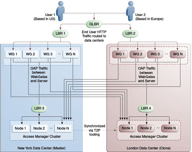
Figure 17-11 illustrates a variation of the deployment topology with local load balancers (LBR 3 and LBR 4) front ending the clusters in each data center. These local load balancers can be Oracle HTTP Servers (OHS) with mod_wl_ohs. The OAP traffic still flows between the WebGates and the Access Manager clusters within the data center but the load balancers perform the DNS routing to facilitate the use of virtual host names.
Note:
For information on monitoring Access Manager server health with a load balancer in use, see Monitoring the Health of an Access Manager Server.
Figure 17-11 Load Balancing Access Manager Components

Description of "Figure 17-11 Load Balancing Access Manager Components"
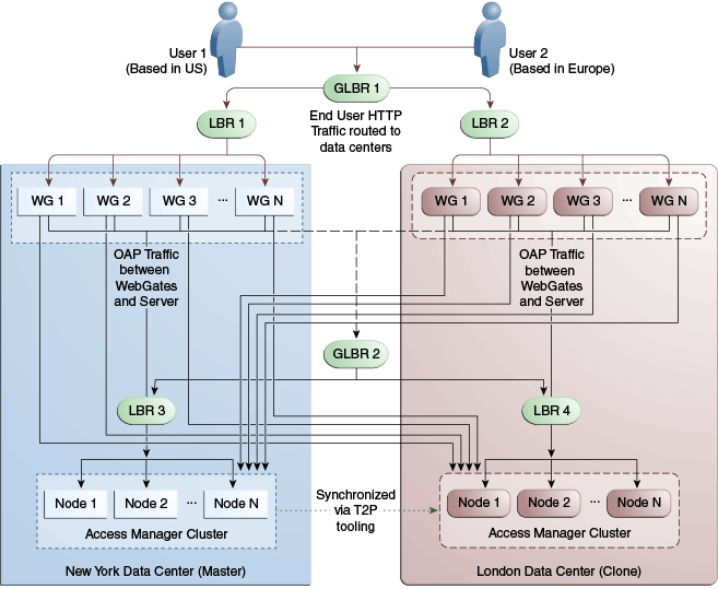
Figure 17-12 illustrates a second variation of the deployment topology with the introduction of a global load balancer (GLBR2) to front end local load balancers (LBR3 and LBR4). In this case, the host names can be virtualized not just within the data center but across the data centers. The WebGates in each data center would be configured to load balance locally but fail over remotely. One key benefit of this topology is that it guarantees high availability at all layers of the stack. Even if the entire Access Manager cluster in a data center were to go down, the WebGates in that data center would fail over to the Access Manager cluster in the other data center.
Figure 17-12 Global Load Balancer Front Ends Local Load Balancer

Description of "Figure 17-12 Global Load Balancer Front Ends Local Load Balancer"