17.3 Active-Active Multi-Data Center Topology Deployment
An Active-Active topology is when Master and Clone Data Centers are exact replicas of each other (including applications, data stores and the like).
They are active at the same time and cater to different sets of users based on defined criteria - geography, for example. A load balancer routes traffic to the appropriate Data Center. Identical Access Manager clusters are deployed in both locales with New York designated as the Master and London as the Clone.
Note:
An Active-Active topology with agent failover is when an agent has Access Manager servers in one Data Center configured as primary and Access Manager servers in the other Data Centers configured as secondary to aid failover scenarios.
Figure 17-9 illustrates the topology for a Multi-Data Center deployment in Active-Active mode. The New York Data Center is designated as the Master and all policy and configuration changes are restricted to it. The London Data Center is designated as a Clone and uses T2P tooling and utilities to periodically synchronize data with the New York Data Center. The global load balancer is configured to route users in different geographical locations (US and Europe) to the appropriate data centers (New York or Europe) based on proximity to the data center (as opposed to proximity of the application being accessed). For example, all requests from US-based User 1 will be routed to the New York Data Center (NYDC) and all requests from Europe-based User 2 will be routed to the London Data Center (LDC).
The Global Load Balancer is configured for session stickiness so once a user has been assigned to a particular data center, all subsequent requests from that user would be routed to the same data center. In this example, User 1 will always be routed to the New York Data Center and User 2 to the London Data Center.
User requests in the respective data centers are intercepted by different WebGates depending on the application being accessed. Each WebGate has the various nodes of the Access Manager cluster within the same data center configured as its primary servers. In this case, the WebGates load balance and failover the local data center.
Note:
Administrators have the flexibility to configure the primary servers for every WebGate in different orders based on load characteristics. Running monitoring scripts in each data center will detect if any of the Access Manager components – the WebGates or the servers – are unresponsive so administrators can reconfigure the load balancers to direct user traffic to a different data center.
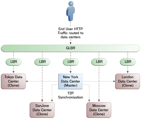
Any number of Clone data centers can be configured to distribute the load across the globe. The only condition is that all Clone data centers are synchronized from a single Master using T2P. Figure 17-10 below depicts an Active-Active Multi-Data Center deployment across five data centers.
Figure 17-10 Active-Active Topology Across Multiple Data Centers

Description of "Figure 17-10 Active-Active Topology Across Multiple Data Centers"
