17.2 Multi-Data Center Deployments
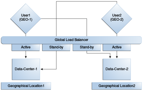
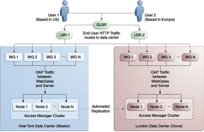
In a Multi-Data Center deployment, each data center will include a full Access Manager installation; WebLogic Server domains will not span the Data Centers.
Global load balancers will maintain user to Data Center affinity although a user request may be routed to a different Data Center when:
-
The data center goes down.
-
A load spike causes redistribution of traffic.
-
Each Data Center is not a mirror of the other. For example, certain applications may only be deployed in a single Data Center.
-
WebGates are configured to load balance within the Data Center and failover across Data Centers.
Figure 17-4 illustrates a basic Multi-Data Center deployment.
The following sections describe several deployment scenarios.
-
Session Adoption Without Re-authentication, Session Invalidation or Session Data Retrieval
-
Session Adoption Without Re-authentication But With Session Invalidation andSession Data Retrieval
-
Authentication and Authorization Requests Served By Different Data Centers
Note:
The OAP connection used for back channel communication does not support load balancing or failover so a load balancer needs to be used.
17.2.1 Session Adoption Without Re-authentication, Session Invalidation or Session Data Retrieval
The following scenario illustrates the flow when the Session Adoption Policy is configured without re-authentication, remote session invalidation and remote session data retrieval.
It is assumed the user has affinity with DC1.
-
User is authenticated by DC1.
On successful authentication, the OAM_ID cookie is augmented with a unique data center identifier referencing DC1 and the user can access applications protected by Access Manager in DC1.
-
Upon accessing an application deployed in DC2, the user is routed to DC2 by a global load balancer.
-
Access Manager in DC2 is presented with the augmented OAM_ID cookie issued by DC1.
On successful validation, Access Manager in DC2 knows that this user has been routed from the remote DC1.
-
Access Manager in DC2 looks up the Session Adoption Policy.
The Session Adoption Policy is configured without reauthentication, remote session invalidation or remote session data retrieval.
-
Access Manager in DC2 creates a local user session using the information present in the DC1 OAM_ID cookie (lifetime, user) and re-initializes the static session information ($user responses).
-
Access Manager in DC2 updates the OAM_ID cookie with its data center identifier.
Data center chaining is also recorded in the OAM_ID cookie.
-
User then accesses an application protected by Access Manager in DC1 and is routed back to DC1 by the global load balancer.
-
Access Manager in DC1 is presented with the OAM_ID cookie issued by itself and updated by DC2.
On successful validation, Access Manager in DC1 knows that this user has sessions in both DC1 and DC2.
-
Access Manager in DC1 attempts to locate the session referenced in the OAM_ID cookie.
-
If found, the session in DC1 is updated.
-
If not found, Access Manager in DC1 looks up the Session Adoption Policy (also) configured without reauthentication, remote session invalidation and remote session data retrieval.
-
-
Access Manager in DC1 updates the OAM_ID cookie with its data center identifier and records data center chaining as previously in DC2.
17.2.2 Session Adoption Without Re-authentication But With Session Invalidation andSession Data Retrieval
The following scenario illustrates the flow when the Session Adoption Policy is configured without re-authentication but with remote session invalidation and remote session data retrieval.
It is assumed the user has affinity with DC1.
-
User is authenticated by DC1.
On successful authentication, the OAM_ID cookie is augmented with a unique data center identifier referencing DC1.
-
Upon accessing an application deployed in DC2, the user is routed to DC2 by a global load balancer.
-
Access Manager in DC2 is presented with the augmented OAM_ID cookie issued by DC1.
On successful validation, Access Manager in DC2 knows that this user has been routed from the remote DC1.
-
Access Manager in DC2 looks up the Session Adoption Policy.
The Session Adoption Policy is configured without reauthentication but with remote session invalidation and remote session data retrieval.
-
Access Manager in DC2 makes a back-channel (OAP) call (containing the session identifier) to Access Manager in DC1 to retrieve session data.
The session on DC1 is terminated following data retrieval. If this step fails due to a bad session reference, a local session is created. See Session Adoption Without Re-authentication, Session Invalidation or Session Data Retrieval.
-
Access Manager in DC2 creates a local user session using the information present in the OAM_ID cookie (lifetime, user) and re-initializes the static session information ($user responses).
-
Access Manager in DC2 rewrites the OAM_ID cookie with its own data center identifier.
-
The user then accesses an application protected by Access Manager in DC1 and is routed to DC1 by the global load balancer.
-
Access Manager in DC1 is presented with the OAM_ID cookie issued by DC2.
On successful validation, Access Manager in DC1 knows that this user has sessions in DC2.
-
Access Manager in DC1 makes a back-channel (OAP) call (containing the session identifier) to Access Manager in DC2 to retrieve session data.
If the session is found, a session is created using the retrieved data. If it is not found, the OAM Server in DC1 creates a new session. The session on DC2 is terminated following data retrieval.
17.2.3 Session Adoption Without Re-authentication and Session Invalidation But With On-demand Session Data Retrieval
Multi-Data Center supports session adoption without re-authentication except that the non-local session are not terminated and the local session is created using session data retrieved from the remote DC.
Note that the OAM_ID cookie is updated to include an attribute that indicates which data center is currently being accessed.
17.2.4 Authentication and Authorization Requests Served By Different Data Centers
Consider a scenario where an authentication request is served by the New York Data Center (NYDC) but the authorization request is presented to the London Data Center (LDC) because of user affinity.
If Remote Session Termination is enabled, the scenario requires a combination of the OAM_ID cookie, the OamAuthn/ObSSO authorization cookie and the GITO cookie to perform the seamless Multi-Data Center operations. This flow (and Figure 17-5 following it) illustrates this. It is assumed that the user has affinity with NYDC.
-
Upon accessing APP1, a user is authenticated by NYDC.
On successful authentication, the OAM_ID cookie is augmented with a unique data center identifier referencing NYDC. The subsequent authorization call will be served by the primary server for the accessed resource, NYDC. Authorization generates the authorization cookie with the NYDC identifier (cluster-id) in it and the user is granted access to the APP1.
-
User attempts to access APP2 in LDC.
-
The WebGate for APP2 finds no valid session in LDC and initiates authentication.
Due to user affinity, the authentication request is routed to NYDC where seamless authentication occurs. The OamAuthn cookie contents are generated and shared with the APP2 WebGate.
-
The APP2 WebGate forwards the subsequent authorization request to APP2's primary server, LDC with the authorization cookie previously generated.
During authorization, LDC will determine that this is a Multi-Data Center scenario and a valid session is present in NYDC. In this case, authorization is accomplished by syncing the remote session as per the configured session adoption policies.
-
A new session is created in LDC during authorization and the incoming session id is set as the new session's index.
Subsequent authorization calls are honored as long as the session search by index returns a valid session in LDC. Each authorization will update the GITO cookie with the cluster-id, session-id and access time. The GITO cookie will be re-written as an authorization response each time.
lf a subsequent authentication request from the same user hits NYDC, it will use the information in the OAM_ID and GITO cookies to determine which Data Center has the most current session for the user. The Multi-Data Center flows are triggered seamlessly based on the configured Session Adoption policies.
Figure 17-5 Requests Served By Different Data Centers
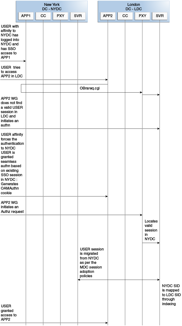
Description of "Figure 17-5 Requests Served By Different Data Centers"
17.2.5 Logout and Session Invalidation
In Multi-Data Center scenarios, logout ensures that all server side sessions across Data Centers and all authentication cookies are cleared out. For session invalidation, termination of a session artifact over the back-channel will not remove the session cookie and state information maintained in the WebGates.
However, the lack of a server session will result in an Authorization failure which will result in re-authentication. In the case of no session invalidation, the logout clears all server side sessions that are part of the current SSO session across Data Centers. This flow (and Figure 17-6 following it) illustrates logout. It is assumed that the user has affinity with NYDC.
-
User with affinity to NYDC gets access to APP1 after successful authentication with NYDC.
-
User attempts to access APP2.
At this point there is a user session in NYDC as well as LDC as part of SSO.
-
User logs out from APP1.
Due to affinity, the logout request will reach NYDC.
-
The NYDC server terminates the user's SSO session and logs out from all the SSO partners.
-
The NYDC server sends an OAP terminate session request to all relevant Data Centers associated with the SSO session - including LDC.
This results in clearing all user sessions associated with the SSO across Data Centers.
Figure 17-6 Logout and Session Invalidation
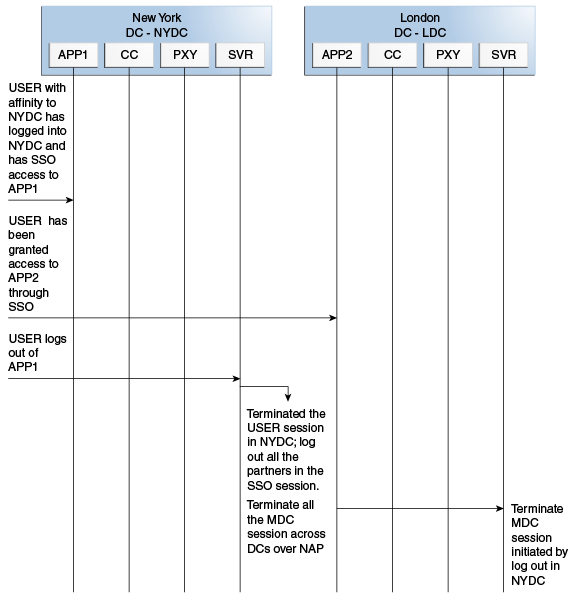
Description of "Figure 17-6 Logout and Session Invalidation"
17.2.6 Stretch Cluster Deployments
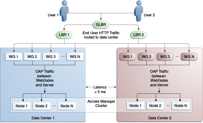
For data centers that are geographically very close and have a guaranteed latency of less than 5 milliseconds, customers can choose a Stretch Cluster deployment.
In this case, unlike the traditional Multi Data Center deployment described in the preceding sections, a single OAM cluster is stretched across multiple data centers; there are some OAM nodes in one Data Center and the remaining nodes in another Data Center. Though the deployment is spread across two data centers, Access Manager treats this as a single cluster. The policy database would reside in one of the Data Centers. The following limitations apply to a Stretch Cluster Deployment.
-
Access Manager depends on the underlying WebLogic and Coherence layers to keep the nodes in sync. The latency between Data Centers must be less than 5 milliseconds at all times. Any spike in the latency may cause instability and unpredictable behavior.
-
The cross data center chatter at runtime in a Stretch Cluster deployment is relatively more than that in the traditional Multi Data Center deployment. In case of the latter, the runtime communication between Data Centers is restricted to use-cases where a session has to be adopted across Data Centers.
-
Since it is a single cluster across Data Centers, it does not offer the same level of reliability/availability as a traditional multi data center deployment. The policy database can become a single point of failure. In a traditional Multi Data Center deployment, each Data Center is self-sufficient and operates independent of the other Data Center which provides far better reliability.
Figure 17-7 illustrates a Stretch Cluster deployment while Figure 17-8 below it illustrates a traditional MDC deployment. Oracle does recommend a traditional multi data center deployment over a Stretch Cluster deployment.
See Also:
Supported Multi-Data Center Topologies