17 Configuring the Server Instance
This chapter describes how to configure and manage a server instance using the dsconfig command or using Oracle Directory Services Manager.
This chapter includes the following sections:
-
Section 17.1, "Managing the Server Configuration Using
dsconfig" -
Section 17.3, "Managing the Server Configuration Using ODSM"
-
Section 17.4, "Managing Administration Traffic to the Server"
17.1 Managing the Server Configuration Using dsconfig
The topics in this section are intended for administrators or users who want to configure and manage a deployed Oracle Unified Directory instance. These topics provide an overview of the dsconfig command-line utility and its use in server configuration.
You can use the dsconfig command to configure both the Oracle Unified Directory directory server and the proxy server. For a list of the supported subcommands for the directory server or proxy instance, and for specific information about this command, see Appendix A, "dsconfig."
You can also use dsconfig to configure some proxy-specific components.
This section contains the following topics:
-
Section 17.1.4, "Configuring a Server Instance Using
dsconfig" -
Section 17.1.5, "Configuring Connection Handlers Using
dsconfig" -
Section 17.1.8, "Configuring Workflow Elements Using
dsconfig" -
Section 17.1.11, "Configuring Access Control Groups With
dsconfig"
17.1.1 Using the dsconfig Command
The dsconfig command provides a simple mechanism for accessing the server configuration. dsconfig presents the configuration as a set of components, each of which can be managed through one or more subcommands.
You can also use dsconfig interactively. In interactive mode, dsconfig functions much like a wizard, walking you through the server configuration. For more information, see Section 17.1.2, "Using dsconfig in Interactive Mode."
You can only use dsconfig to configure a running server instance. Offline configuration is not supported by dsconfig.
Like the other administration commands, dsconfig uses the administration connector to access the server. For more information, see Section 17.4, "Managing Administration Traffic to the Server." All of the examples in this section assume that the administration connector is listening on the default port (4444) and that the command is accessing the server running on the local host. If this is not the case, the --port and --hostname options must be specified.
This section contains the following topics:
-
Section 17.1.1.1, "Running
dsconfigand Certificate Checking" -
Section 17.1.1.3, "Working with
dsconfigAdvanced Properties"
17.1.1.1 Running dsconfig and Certificate Checking
The dsconfig command accesses the server over a secured connection with certificate authentication. If you run dsconfig in interactive mode, then you are prompted about how you want to trust the certificate.
If you run dsconfig in non-interactive mode (that is, with the -n option), specification of the trust store parameters depends on whether you run the command locally or remotely.
-
Running dsconfig locally. (The command is launched on the server that you are administering.) If you do not specify the trust store parameters, the server uses the local instance trust store by default. Unless you specify otherwise, the local instance trust is
INSTANCE_DIR/OUD/config/admin-truststore. -
Running dsconfig remotely. (The command is launched on a different server to the one you are administering.) You must specify the trust store parameters or the
-X(--trustAll) option. The easiest way to specify the trust store parameters is to run the command once in interactive mode and to save the certificate that is presented by the server in your trust store.$ dsconfig >>>> >>>> Specify Oracle Unified Directory LDAP connection parameters Directory server hostname or IP address [host1.example.com]: Directory server administration port number [4444]: Administrator user bind DN [cn=Directory Manager]: Password for user 'cn=Directory Manager': How do you want to trust the server certificate? 1) Automatically trust 2) Use a truststore 3) Manually validate Enter choice [3]: 3 Administrator user bind DN [cn=Directory Manager]: Password for user 'cn=Directory Manager': Server Certificate: User DN : CN=host1.example.com, O=Administration Connector Self-Signed Certificate Validity : From 'Wed Apr 29 11:13:21 MEST 2009' To 'Fri Apr 29 11:13:21 MEST 2011' Issuer : CN=host1.example.com, O=Administration Connector Self-Signed Certificate Do you trust this server certificate? 1) No 2) Yes, for this session only 3) Yes, also add it to a truststore 4) View certificate details Enter choice [2]: 3 Truststore path: /local/instances/certificates/jctruststore Password for keystore '/local/instances/certificates/jctruststore': ...When you have saved the certificate in the trust store, you can specify those trust store parameters in non-interactive mode.
$ dsconfig -h localhost -p 4444 list-connection-handlers -n \
--trustStorePath /local/instances/certificates/jctruststore \
--trustStorePasswordFile /local/instances/certificates/jctruststore.pin -j pwd-file
Connection Handler       : Type : enabled : listen-port : use-ssl
-------------------------:------:---------:-------------:--------
JMX Connection Handler   : jmx  : false   : 1689        : false
LDAP Connection Handler  : ldap : true    : 1389        : false
LDAPS Connection Handler : ldap : false   : 636         : true
LDIF Connection Handler  : ldif : false   : -
17.1.1.2 Working with dsconfig Subcommands
dsconfig provides an intuitive list of subcommands to manage various elements of the configuration.
You can use these subcommands to add, delete, list, view, and modify different components:
| Subcommand | Function |
|---|---|
dsconfig create-component options |
Creates a new component |
dsconfig delete-component options |
Deletes an existing component |
dsconfig get-component-prop options |
Displays the properties of a component |
dsconfig list-components options |
Lists the existing defined components |
dsconfig set-component-prop options |
Modifies the properties of a component |
For example, the following five subcommands are used to manage connection handlers:
| Subcommand | Function |
|---|---|
dsconfig create-connection-handler options |
Creates connection handlers |
dsconfig delete-connection-handler options |
Deletes connection handlers |
dsconfig get-connection-handler-prop options |
Displays the properties of a connection handler |
dsconfig list-connection-handlers options |
Lists the existing defined connection handlers |
dsconfig set-connection-handler-prop options |
Modifies the properties of a connection handler |
Not all types of components can be created and deleted. For example, a directory server has only a single global configuration. For this reason, the global configuration is managed with only two subcommands:
| Subcommand | Function |
|---|---|
dsconfig get-global-configuration-prop options |
Displays the global configuration properties |
dsconfig set-global-configuration-prop options |
Modifies the global configuration properties |
The configurable properties of all components can be queried and modified to change the behavior of the component. For example, an LDAP connection has properties that determine its IP listener address, its port, and its SSL configuration.
17.1.1.3 Working with dsconfig Advanced Properties
Some component properties are considered advanced properties. These advanced properties are not displayed by default, and have default values that apply in most cases. If you want to modify the advanced properties or their values, use --advanced before the subcommand. For example:
$ dsconfig --advanced get-extension-prop
17.1.2 Using dsconfig in Interactive Mode
Unless you specify all configuration parameters and the -n (--no-prompt) option, dsconfig runs in interactive mode. Interactive mode functions like a wizard, walking you through the server configuration. Interactive mode is a good approach to start using dsconfig.
When you run dsconfig in interactive mode, you can specify that you want the equivalent command (including all your selections) to be displayed or written to a file.
The following example shows how to use the --displayCommand option to display the equivalent non-interactive command when configuring the trust manager. Notice that the equivalent command is displayed at the point at which the command has been applied and validated by the directory server.
$ dsconfig -h localhost -p 4444 -D "cn=directory manager" -j pwd-file --displayCommand
...
The TrustStore Manager Provider was modified successfully

The equivalent non-interactive command-line is:
dsconfig --hostname "localhost" --port "4444" --bindDN "cn=directory
manager" --bindPasswordFile pwd-file --trustAll
set-trust-manager-provider-prop --provider-name "PKCS12" --set
"enabled:true"
To copy the equivalent command to a file, use the --commandFilePath option, as shown in the following example:
$ dsconfig -h localhost -p 4444 -D "cn=directory manager" -j pwd-file --commandFilePath /tmp/filename
17.1.3 Getting Help With dsconfig
The dsconfig command has extensive online help that is accessed using the --help option. This section provides an overview, and contains the following topics:
-
Section 17.1.3.3, "Getting Help for an Individual Subcommand"
-
Section 17.1.3.4, "Displaying a Summary of a Component's Properties"
17.1.3.1 Displaying Global Usage
Use the following command to display dsconfig's global usage:
$ dsconfig --help
17.1.3.2 Finding the Correct Subcommand
The global usage information does not include the list of available subcommands. To retrieve the list of subcommands, use one of the --help-xxx options, where xxx determines the group of subcommands to be displayed.
Note:
Use the--help-all option used to display all of the available subcommands.For example, to find all the subcommands relating to distribution, use the following command:
$ dsconfig --help-distribution
17.1.3.3 Getting Help for an Individual Subcommand
When you have determined which subcommand you want, you can get more detailed help on that subcommand using the subcommand --help option as follows:
$ dsconfig create-monitor-provider --help
17.1.3.4 Displaying a Summary of a Component's Properties
The dsconfig command has built-in documentation for all of the components and their properties. You can access this documentation using the list-properties subcommand. For example, a summary of the properties associated with a work queue can be displayed using the following command:
$ dsconfig list-properties -c work-queue
If the -c option is not specified, a summary of the properties for all components is displayed.
17.1.3.5 Displaying Detailed Help on a Property
The summary table displays only brief usage information for each property. More detailed information are available using the verbose mode of the list-properties subcommand:
$ dsconfig list-properties -c work-queue --property num-worker-threads -v
If the --property option is not specified, verbose help is provided for all the work-queue properties.
17.1.4 Configuring a Server Instance Using dsconfig
The dsconfig command is the recommended utility for accessing the server configuration. Accessing the configuration directly over LDAP, using the ldap* utilities is discouraged. This section describes the utility to access the server components and contains the following topics:
-
Section 17.1.4.3, "Configuring How Server Changes Are Recorded"
-
Section 17.1.4.6, "Modifying the Values of a Multi-Valued Property"
17.1.4.1 Viewing the Properties of a Component
You can use a component's get-xxx-prop subcommand to view a list of its properties. Each component is associated with a single LDAP entry in the server configuration, and each property is associated with a single LDAP attribute.
To display the properties of the default LDAP connection handler, run the following command:
$ dsconfig -h localhost -p 4444 -D "cn=directory manager" -j pwd-file -X -n \
  get-connection-handler-prop --handler-name "LDAP Connection Handler"

Property : Value(s)
------------------------:-------------------------------------------------------
allow-ldap-v2 : true
allow-start-tls : false
allowed-client : -
denied-client : -
enabled : true
keep-stats : true
key-manager-provider : -
listen-address : 0.0.0.0
listen-port : 1389
ssl-cert-nickname : server-cert
ssl-cipher-suite : -
ssl-client-auth-policy : optional
ssl-protocol : -
trust-manager-provider : -
use-ssl : false
The dsconfig command displays the default values or behavior for properties that have not been customized.
17.1.4.2 Listing Components
You can view a list and summary of the instances of one component using the component's list-xxxs subcommand. This can be particularly useful if you have more than one instance of the same component.
For example, to list the configured connection handlers, run this command:
$ dsconfig -h localhost -p 4444 -D "cn=directory manager" -j pwd-file -X -n \
  list-connection-handlers
Depending on your installation, the output will be similar to the following.
Connection Handler       : Type : enabled : listen-port : use-ssl
-------------------------:------:---------:-------------:--------
JMX Connection Handler   : jmx  : false   : 1689        : false
LDAP Connection Handler  : ldap : true    : 1389        : false
LDAPS Connection Handler : ldap : false   : 636         : true
LDIF Connection Handler  : ldif : false   : -           : -
SNMP Connection Handler  : snmp : false   : 161         : -
17.1.4.3 Configuring How Server Changes Are Recorded
Whenever someone makes a change to the server (ADD, MODIFY, DELETE, etc.), Oracle Unified Directory stores that change as an entry containing information; including which object was changed, which attributes were changed, and who made the changes.
The server itself automatically generates and handles either the modifiersName attribute or the creatorsName attribute, as follows:
-
For MODIFYs and DELETEs, the server creates the
modifiersNameattribute. -
For ADDs, the server creates the
creatorsNameattribute.
Server changes can be explicitly performed by one user (user1) or by a user (user1) acting as another user (user2).
-
If a single user (user1) performs the change, then there is no ambiguity and that modifiers's name or creator's name is stored.
-
If a user (user1) performs the change acting as another user (user2), then user1 binds to the server, but "becomes" user2 to modify the object.
You can choose how you want the server to record these changes by configuring the use-authid-for-audit-attrs attribute. For example,
-
False (default): Stores the authentication ID, such as the bind DN, of the bound user (user1) as the modifier.
-
True: Stores the authorization ID of the proxied user (user2) as the modifier (If relevant, for example, when using proxy auth). The server records the authorization ID in the
creatorsNameormodifiersNameduring a write operation on the entry.
The following example illustrates setting the use-authid-for-audit-attrs attribute value to true, so that the server will record the proxied user (user2) as the modifier:
./dsconfig set-plugin-prop \
   --plugin-name LastMod \
   --set use-authid-for-audit-attrs:true \
   --hostname localhost \
   --port 4444 \
   --trustAll \
   --bindDN cn=Directory\ Manager \
   --bindPasswordFile /tmp/dsconfigpwd \
   --no-prompt
17.1.4.4 Creating a Component
You can create new instances of a component using the component's create-xxx subcommand.
Components often have several subtypes. For example, there are four types of connection handler: LDAP, LDIF, JMX, and SNMP. Because all of these are created using the same subcommand, you must specify the type of component that you want to create using the -t or --type subcommand.
When you create a new component, you must specify the component's mandatory properties. The mandatory properties depend on the type of component that is being created. For example, an LDAP connection handler might have different mandatory properties to a JMX connection handler. If a mandatory property is left undefined, dsconfig enters interactive mode and prompts you for the undefined properties. If you include the -n (non-interactive) option, dsconfig fails to create the component and displays an error message indicating which properties need to be defined.
-
Display the types of connection handler that can be created by accessing the help for the connection handler component.
$ dsconfig create-connection-handler --help Usage: dsconfig create-connection-handler {options} Creates Connection Handlers Global Options: See "dsconfig --help" SubCommand Options: --handler-name {NAME} The name of the new Connection Handler --set {PROP:VALUE} Assigns a value to a property where PROP is the name of the property and VAL is the single value to be assigned. Specify the same property multiple times in order to assign more than one value to it -t, --type {TYPE} The type of Connection Handler which should be created. The value for TYPE can be one of: custom | jmx | ldap | ldif | snmp -
Create a new LDAP connection handler, specifying values for the mandatory
enabledand thelisten-portproperties.$ dsconfig -h localhost -p 4444 -D "cn=directory manager" -j pwd-file -X -n \ create-connection-handler -t ldap --handler-name "My LDAP Connection Handler"
An error message similar to the following will be displayed.
The LDAP Connection Handler could not be created because the following
mandatory properties were not defined:

Property     Syntax
----------------------------------
enabled      false | true
listen-port  1 <= INTEGER <= 65535
17.1.4.5 Modifying Component Properties
The properties of a component can be modified using the component's set-xxx-prop subcommand. Multiple properties can be modified at the same time using multiple occurrences of the --set option. The following example uses the set-connection-handler-prop subcommand to modify the properties of a connection handler.
Note:
Many components have a Java class property that specifies the name of a Java class to be used as the implementation of the component. Do not modify this property, as doing so could prevent your server from operating correctly. These properties are treated as advanced properties and hidden from view unless you rundsconfig with the --advanced option.For example, to configure the LDAP connection handler to accept LDAPv2 connections, run this command:
$ dsconfig -h localhost -p 4444 -D "cn=directory manager" -j pwd-file -X -n \
  set-connection-handler-prop --handler-name="LDAP Connection Handler" \
  --set allow-ldap-v2:true
17.1.4.6 Modifying the Values of a Multi-Valued Property
You can set multiple values for a property using the --add option multiple times in the same dsconfig command.
This example sets multiple values for the allowed-client property.
To restrict connections through the LDAP connection handler to specific clients, run these commands:
$ dsconfig -h localhost -p 4444 -D "cn=directory manager" -j pwd-file -n \
  set-connection-handler-prop --handler-name "LDAP Connection Handler" \
  --add allowed-client:myhost --add allowed-client:myhost.example \
  --add allowed-client:myhost.example.com
17.1.4.7 Deleting a Component
Existing instances of a component can be removed using the dsconfig delete-xxx subcommand
The following example deletes the LDAP connection handler that was created in the previous example:
$ dsconfig -h localhost -p 4444 -D "cn=directory manager" -j pwd-file -X -n \
  delete-connection-handler --handler-name "My LDAP Connection Handler"
17.1.4.8 Using dsconfig in Batch Mode
You can use the -F or --batchFilePath option of the dsconfig command to specify operations that are completed in a single command by consolidating those operations in a file. Consolidating these operations can significantly improve performance when several dsconfig commands are required.
To use dsconfig in batch mode, complete the following steps:
-
Create a script that contains the required commands for creating a new back end that is used to store a new suffix.
For example, the following file (named
new-backend.txt) achieves three separate tasks:-
Creates the db-local-backend workflow element
-
Adds a set of index entry limit for the uniquemember attribute (for example, how to set properties, but this step is not mandatory)
-
Creates the workflow for the new suffix
-
Registers the new suffix in the default network group
create-workflow-element --element-name myBackend --type db-local-backend \
--set enabled:true --set base-dn:cn=myexample,cn=com
set-local-db-index-prop --element-name myBackend --index-name uniqueMember \
--set index-entry-limit:5000
create-workflow --workflow-name myWorkflow --set base-dn:cn=myexample,cn=com \
--set enabled:true --set workflow-element:myBackend
set-network-group-prop --group-name network-group --add workflow:myWorkflow
-
-
Run the
dsconfigcommand with that file as a parameter.$ dsconfig -h localhost -p 4444 -D cn="directory manager" -j pwd-file \ -F new-backend.txt -X -n
17.1.5 Configuring Connection Handlers Using dsconfig
Connection handlers are responsible for handling all interaction with client applications, including accepting connections, reading requests, and sending responses.
For information about configuring secure connections, see Section 26.5, "Configuring SSL and StartTLS for LDAP and JMX."
The section describes how to configure the connection handlers using the dsconfig command, and contains the following topics:
These sections provide examples on only a few aspects of the configuration. For details about all the configuration properties, use the following command:
$ dsconfig list-properties -c connection-handler
17.1.5.1 Viewing All Connection Handlers
Oracle Unified Directory supports the following types of connection handler:
-
LDAP connection handler. This connection handler is used to interact with clients using LDAP. It provides full support for LDAPv3 and limited support for LDAPv2.
-
LDAPS connection handler. This connection handler is used to interact with clients using LDAP over SSL.
-
LDIF connection handler. This connection handler is used to process changes in the server using internal operations.
-
JMX connection handler. This connection handler allows interactions with clients using the Java Management Extensions (JMX) framework and the Remote Method Invocation (RMI) protocol.
-
SNMP. This connection handler is used to process SNMP requests to retrieve monitoring information described by MIB 2605. The supported SNMP protocols are SNMP V1, V2c and V3.
To display all configured connection handlers, along with their basic properties, use the dsconfig list-connection-handlers command.
$ dsconfig -h localhost -p 4444 -D "cn=directory manager" -j pwd-file -X -n \
  list-connection-handlers
Connection Handler       : Type : enabled : listen-port : use-ssl
-------------------------:------:---------:-------------:--------
JMX Connection Handler   : jmx  : false   : 1689        : false
LDAP Connection Handler  : ldap : true    : 1389        : false
LDAPS Connection Handler : ldap : false   : 636         : true
LDIF Connection Handler  : ldif : false   : -           : -
SNMP Connection Handler  : snmp : false   : 161         : -
17.1.5.2 Configuring the LDAP Connection Handler
The following command displays the properties of the LDAP connection handler:
$ dsconfig -h localhost -p 4444 -D "cn=directory manager" -j pwd-file -X -n \
  get-connection-handler-prop --handler-name "LDAP Connection Handler"
Depending on your configuration, the output will be similar to the following.
Property               : Value(s)
-----------------------:------------
allow-ldap-v2          : true
allow-start-tls        : false
allowed-client         : -
denied-client          : -
enabled                : true
keep-stats             : true
key-manager-provider   : -
listen-address         : 0.0.0.0
listen-port            : 1389
ssl-cert-nickname      : server-cert
ssl-cipher-suite       : -
ssl-client-auth-policy : optional
ssl-protocol           : -
trust-manager-provider : -
use-ssl                : false
17.1.5.2.1 Controlling Which Clients Have LDAP Access to the Directory Server
You can specify a list of clients that may or may not access the directory server over LDAP. To do this, set the allowed-client or denied-client property of the LDAP connection handler. These properties take an IP address or subnetwork with subnetwork mask as values.
By default, these properties are not set and all clients are allowed access. Changes to these properties take effect immediately but do not interfere with connections that are already established.
This example permits access only to clients in the subnet mask 255.255.255.10.
Run the dsconfig command as follows:
$ dsconfig -h localhost -p 4444 -D "cn=directory manager" -j pwd-file -X -n \
  set-connection-handler-prop --handler-name "LDAP Connection Handler" \
  --set allowed-client:255.255.255.10
17.1.5.3 Configuring the LDIF Connection Handler
The LDIF connection handler is disabled by default. This connection handler can be used to process changes in the server using internal operations. The changes to be processed are read from an LDIF file.
The following command displays the default properties of the LDIF connection handler:
$ dsconfig -h localhost -p 4444 -D "cn=directory manager" -j pwd-file -n \
  get-connection-handler-prop --handler-name "LDIF Connection Handler"
Depending on your installation, the output will be similar to the following.
Property       : Value(s)
---------------:-------------------------
allowed-client : -
denied-client  : -
enabled        : false
ldif-directory : config/auto-process-ldif
poll-interval  : 5 s
The ldif-directory property specifies the directory in which the LDIF files are located. The connection handler checks if there are any files in this directory, at an interval specified by the poll-interval property. The connection handler then processes the changes contained in those files as internal operations and writes the result to an output file with comments indicating the result of the processing.
17.1.5.3.1 Enabling the JMX Alert Handler Through the LDIF Connection Handler
This example demonstrates how to enable the JMX alert handler through the LDIF connection handler.
-
Check the status of the JMX alert handler (disabled by default).
$ dsconfig -h localhost -p 4444 -D "cn=directory manager" -j pwd-file -X -n \
  get-alert-handler-prop --handler-name "JMX Alert Handler"
Depending on your installation, the output will be similar to the following.
Property            : Value(s)
--------------------:---------
disabled-alert-type : -
enabled             : false
enabled-alert-type  : -
-
Create an LDIF file in the default LDIF directory that enables the JMX alert handler.
$ cd ../config/
$ mkdir auto-process-ldif
$ cd auto-process-ldif/
$ cat > disable-jmx.ldif << EOM
> dn: cn=JMX Alert Handler,cn=Alert Handlers,cn=config
> changetype: modify
> replace: ds-cfg-enabled
> ds-cfg-enabled: true
> EOM
$
-
After a period of time longer than
poll-interval, recheck the status of the JMX alert handler.$ dsconfig -h localhost -p 4444 -D "cn=directory manager" -j pwd-file -X -n \ get-alert-handler-prop --handler-name "JMX Alert Handler" Property : Value(s) --------------------:--------- disabled-alert-type : - enabled : true enabled-alert-type : -
17.1.5.4 Configuring the JMX Connection Handler
The following command displays the default properties of the JMX connection handler:
$ dsconfig -h localhost -p 4444 -D "cn=directory manager" -j pwd-file -X -n \
  get-connection-handler-prop --handler-name "JMX Connection Handler"
Depending on your installation, the output will be similar to the following.
Property             : Value(s)
---------------------:------------
allowed-client       : -
denied-client        : -
enabled              : false
key-manager-provider : -
listen-port          : 1689
ssl-cert-nickname    : server-cert
use-ssl              : false
17.1.5.4.1 Changing the Port on Which the Server Listens for JMX Connections
This example changes the port on which the server listens for JMX connections to 1789.
Use the dsconfig command as follows:
$ dsconfig -h localhost -p 4444 -D "cn=directory manager" -j pwd-file -n \
  set-connection-handler-prop \
  --handler-name "JMX Connection Handler" --set listen-port:1789
17.1.6 Configuring Network Groups Using dsconfig
Network groups are the single entry point of all client requests to the Oracle Unified Directory. The network group handles all client interactions, dispatching them and delegating the treatment of the request to workflows. A client connection is associated to the network group with the highest priority and for which all the criteria are met. During installation, a default network group with a priority of 1 is created. To set request filtering policies or resource limits, you must create a network group quality of service policy.
Each network group is associated with one or more workflows. The workflows provide access to a naming context (or suffix). By associating a workflow with a network group, you indicate to the network group which naming contexts are available. Typically to create a network group, you would already have a workflow created. For information about workflows, see Section 17.1.7, "Configuring Workflows Using dsconfig."
This section describes how to configure network groups using the dsconfig command, and covers the following topics:
-
Section 17.1.6.3, "Creating a Network Group Quality of Service Policy"
-
Section 17.1.6.4, "Modifying a Network Group Quality of Service Policy"
-
Section 17.1.6.5, "Relocating the Root DSE Entry for a Network Group"
-
Section 17.1.6.6, "Customizing the Root DSE Entry for a Network Group"
All the commands in the following procedures specify the hostname (-h), the admin port (-p), the bind DN (-D), and the bind password file (-j). The examples use the -X option to trust all certificates.
17.1.6.1 Creating a Network Group
You can create many network groups, in which case client requests will be handled by the network group with the highest priority, for which the criteria are met. Therefore, when you create a network group, you must consider all the network groups you plan to create, and the priority of each. The priority can be 0 or above, where 0 is the highest priority.
It is possible to create two network groups with the same priority. However, if two or more network groups have the same priority and match the client request, the network group that will handle the request is random, among those matching the client request. You should therefore specify a different priority for each network group.
The default properties of a new network group are as follows.
Property                 Value(s)
----------------------------------------------------------------------
allowed-auth-method      All authorization methods are allowed.
allowed-bind-dn          All bind DNs are allowed.
allowed-bind-id          All bind IDs are allowed.
allowed-client           All clients with addresses that do not match
                         an address on the deny list are allowed. If
                         there is no deny list, then all clients are
                         allowed.
allowed-portAll          All port numbers are allowed.
allowed-protocol         All supported protocols are allowed.
certificate-mapper       The global certificate mapper will be used.
denied-client            If an allow list is specified, then only
                         clients with addresses on the allow list are
                         allowed. Otherwise, all clients are allowed.
enabled                  true
generic-identity-mapper  The global generic identity mapper will be
                         used.
gssapi-identity-mapper   The global GSSAPI identity mapper will be
                         used.
is-security-mandatory    false
priority                 1
workflow                 userroot0
To create a network group, use the dsconfig create-network-group command, as follows:
$ dsconfig -h localhost -p 4444 -D "cn=Directory Manager" -j pwd-file -X -n \
  create-network-group --group-name network-group1 --set enabled:true\
  --set workflow:workflow1 --set priority:1
After you have created a network group, you can associate a network group quality of service policy to it. For information about creating a quality of service policy, see Section 17.1.6.3, "Creating a Network Group Quality of Service Policy."
17.1.6.2 Modifying Network Group Properties
The network group properties filter the traffic and indicate how a request is directed.
You can modify network group properties, using the dsconfig set-network-group-prop command. For example, to modify the priority of the network group:
$ dsconfig -h localhost -p 4444 -D "cn=Directory Manager" -j pwd-file -X -n \
  set-network-group-prop --group-name network-group1 --set priority:3
You can configure the network group properties to set the following criteria:
-
the authentication method allowed between the client and the network group (
allowed-auth-method). -
the bind DN allowed to connect to the network group (
allowed-bind-dn). -
the list of clients authorized to access the Oracle Unified Directory (
allowed-client), expressed by the IP address or name of the client. If no allowed client list is provided, all clients are allowed, assuming they are not listed in the denied client list. -
the protocol allowed to connect to the Oracle Unified Directory (
allowed-protocol). If none is specified, then all protocols are allowed. -
the allowed port (s) to configure client connection to connect to the Oracle Unified Directory (
allowed-portAll). If none is specified, then all the connection handlers ports are allowed. -
the name of the certificate mapper that should be used to match client certificates to user entries (
certificate-mapper). If none is specified, then global certificate mapper is used. -
the list of clients not authorized to access the Oracle Unified Directory (
denied-client). If no denied client list is provided, then all clients are authorized, assuming there is no limitation set by an allowed client list. -
the set of identity mappers that will be used by the network group to map an identity while performing SIMPLE, non-GSSAPI SASL bind requests and proxy authorization controls (
generic-identity-mapper). -
the set of identity mappers that will be used by the network group to map an identity while performing GSSAPI/SASL bind requests (
gssapi-identity-mapper). -
whether security between the client and the Oracle Unified Directory is always required (
is-security-mandatory). -
the priority of the network group (
priority). A client connection is first compared against the network group with the highest priority. If the client connection does not match its connection criteria, the client connection is compared against the network group with the next highest priority, and so on. If no network group is selected, the client connection is rejected.
For example, you can ensure that no connections are accepted from the IP address 208.77.188.166, by network-group1 as follows:
$ dsconfig -h localhost -p 4444 -D "cn=Directory Manager" -j pwd-file -X -n \
  set-network-group-prop --group-name network-group1 \
  --set denied-client:208.77.188.166
17.1.6.2.1 Setting an Allowed or Denied Client List
For allowed-client and denied-client lists, you must be aware of the name service configuration on the server. For example, if the name service knows the host as myclienthost.example.com, you must specify myclienthost.example.com as the value, and not just myclienthost. Similarly, if the name service knows the host as myclienthost, you must specify the value as myclienthost. If you do not know how the name service is configured, you should specify both the fully qualified domain name (for example myclienthost.oracle.com) and the short name (myclienthost) of the machine. Specifying multiple values will ensure that the name is resolved correctly. For example:
$ dsconfig -h localhost -p 4444 -D "cn=Directory Manager" -j pwd-file -X -n \
  set-network-group-prop \
  --group-name network-group1 \
  --add denied-client:myhost \
  --add denied-client:myhost.example \
  --add denied-client:myhost.example.com
To avoid any issues, use the IP address for clarity.
If you use localhost or the name of the local machine when connecting to Oracle Unified Directory, the IP addresses of the client will be different. To prevent connections from the localhost, specify both localhost and the name of the local machine in the list of denied clients.
17.1.6.3 Creating a Network Group Quality of Service Policy
You can, optionally, associate a quality of service (QoS) policy with a network group. A QoS policy applies additional filtering criteria to client connections to determine how the network group handles the request.
Oracle Unified Directory supports four types of QoS policy:
-
Request filtering policy
-
Resource limits
-
Affinity
-
Referral
Note:
ODSM accesses an Oracle Unified Directory instance over the administration connector. The administration connector is not subject to the QoS policies defined for a network group. ODSM therefore bypasses the QoS policies defined for a network group. For more information, see Section 17.4, "Managing Administration Traffic to the Server".To create a network group quality of service policy, use the dsconfig create-network-group-qos-policy command. You must specify the name of the network group to which the quality of service policy applies, and the type of quality of service policy.
17.1.6.3.1 Creating a Request Filtering Quality of Service Policy
A request filtering policy applies the following criteria to an incoming client request:
-
allowed-attributes: list of attributes that can be specified in the filter of a search request -
allowed-operations: type of operation accepted by the network group. For example, you can specify that a network group should accept only read requests. -
allowed-search-scopes: scope of a search accepted, for example one-level only. -
allowed-subtrees: list of specific subtrees that can be specified as a base DN in a search request -
prohibited-attributes: list of attributes which, if specified in the filter of a search request, will be rejected -
prohibited-subtrees: list of specific subtrees that, if specified as base DNs in a search request, may not be specified will not manage a request
The following example defines a request filtering policy that ensures that users can only search and not modify data:
$ dsconfig -h localhost -p 4444 -D "cn=Directory Manager" -j pwd-file -X -n \
  create-network-group-qos-policy --group-name network-group1 \
  --type request-filtering --set allowed-operations:search
17.1.6.3.2 Creating a Resource Limit Quality of Service Policy
A resource limit policy sets specific limits on the client connections that can access the server through that network group. The following limits can be defined:
-
max-concurrent-ops-per-connection: the maximum number of simultaneous operations per established connection. To run the server in synchronous mode, set the maximum to 1. -
max-ops-per-connection: the maximum number of operations per connection. -
max-connections: the maximum number of concurrent client connections to the server. If you do not set a maximum number of connections, the server limit is used. -
max-connections-from-same-ip: the maximum number of connections from the same IP address. Set this parameter if you want to avoid Denial of Service attacks. This parameter should not be set if you know that most requests typically come from the same client. -
max-ops-per-interval: the maximum number of operations per specified interval. For example, a setting of 1,000 will limit the number of operations to 1,000 per the interval set usingmax-ops-interval. -
max-ops-interval: the interval during which the number of operations is counted for themax-ops-per-intervalparameter. For example, an interval set to one second results in operations being counted per second. The limit (max-ops-per-interval) is checked and enforced during each interval. -
min-substring-length: the minimum search string length. The shorter the search string, the more results that need to be found and displayed. It is therefore useful to set a minimum search string length in the substring search filter to limit the resources that are used. -
size-limit: the maximum number of entries that can be returned to the client during a single search operation. It is recommended that you keep the default setting for this property. -
time-limit: the maximum length of time that should be spent processing a search operation. It is recommended that you keep the default setting for this property.
The following example defines a resource limit policy that ensures that a user enters a search string of at least five characters, to limit the number of return values:
$ dsconfig -h localhost -p 4444 -D "cn=Directory Manager" -j pwd-file -X -n \
  create-network-group-qos-policy --group-name network-group1 \
  --type resource-limits --set min-substring-length:5
17.1.6.3.3 Creating an Affinity Quality of Service Policy
In a load balancing deployment, you can use affinity to override the regular routing process. The properties of the affinity policy determine the routing process that should be followed.
You can configure the following properties:
-
affinity-policy: Specifies the routing policy to use.The affinity policy can take one of the following values:
-
all-requests-after-first-request -
all-requests-after-first-write-request -
all-write-requests-after-first-write-request -
first-read-request-after-write-request
Specific operations will set affinity, depending on the affinity policy. For the first policy in the previous list (
all-requests-after-first-request) all operations will set affinity. For the remaining policies (all-requests-after-first-write-request,all-write-requests-after-first-write-request, andfirst-read-request-after-write-request) only anADD,DELETE,MODorMODDNoperation will set affinity. -
-
affinity-timeout: Defines the duration during which the affinity applies.
Even when affinity has been set by a previous operation, the load balancing algorithm is only bypassed in specific situations, depending on the affinity policy and the current operation type. If the affinity policy is all-requests-after-first-request or all-requests-after-first-write-request, the affinity route will be used for every operation type, unless the affinity timeout has expired. If the affinity policy is all-write-requests-after-first-write, the affinity route will be used for any ADD, DELETE, MOD or MODDN operation, unless the timeout has expired. The affinity route will not be used for other operations. If the affinity policy is first-read-request-after-write-request, the affinity route will be used for all operations except ADD, DELETE, MOD or MODDN operations, unless the timeout has expired.
The following example sets an affinity policy that can be set by any operation and used for all operations, for a maximum of sixty seconds.
$ dsconfig -h localhost -p 4444 -D "cn=Directory Manager" -j pwd-file -X -n \
  create-network-group-qos-policy --group-name network-group1 \
  --type affinity --set affinity-timeout:60s \
  --set affinity-policy:all-requests-after-first-request
Note:
The affinity feature can be used with all load balancing algorithms except for the failover algorithm. With the failover algorithm, only one route is active at a time. The active route changes when the remote server goes down, so all connections to the remote server are broken. Affinity can therefore not apply in a failover scenario.17.1.6.3.4 Creating a Referral Quality of Service Policy
You can configure the behavior of a proxy server when a referral is received from the remote LDAP server by defining a referral quality of service policy. The referral itself must be defined on the remote LDAP server.
When you create a network group quality of service, you can set the following referral properties:
-
Maximum number of hops supported (
referral-hop-limit) when the referral policy is set tofollow. The default is set to 5. -
Define the type of referral policy (
referral-policy), such asdiscard,forward, orfollow. This property defines how a referral will be treated by the network group.
For example, the referral-policy is set by default to forward. You can change it to discard or to follow, as follows:
$ dsconfig -h localhost -p 4444 -D "cn=Directory Manager" -j pwd-file -X -n \
  create-network-group-qos-policy --group-name network-group1 \
  --type referral --set referral-policy:follow
17.1.6.4 Modifying a Network Group Quality of Service Policy
To modify a QoS policy, use the dsconfig set-network-group-qos-policy-prop command, specifying the network group name and the policy type.
The following example sets the minimum search string limit of a resource limits quality of service policy.
$ dsconfig -h localhost -p 4444 -D "cn=Directory Manager" -j pwd-file -X -n \
  set-network-group-qos-policy-prop --group-name network-group1 \
  --policy-type resource-limits --set min-substring-length:5
17.1.6.5 Relocating the Root DSE Entry for a Network Group
The Root DSE is a special entry that provides information about the server's name, version, naming contexts, and supported features. The Root DSE entry of a network group can be in a local server or a remote server.
To relocate the Root DSE, use the dsconfig set-network-group-prop command, as shown in the following example:
$ dsconfig -h localhost -p 4444 -D "cn=Directory Manager" -j pwd-file -X -n \
  set-network-group-prop --group-name network-group1 \
  --set relocated-rootdse-workflow-element:<new rootDSE workflow element>  \
The value of the relocated-rootdse-workflow-element property is the workflow element where a Root DSE can be found (This is the entry returned by a search on the null DN).
17.1.6.6 Customizing the Root DSE Entry for a Network Group
The default Root DSE view may not display all the information you want to view. For example, by default the Root DSE view may not display all supportedControls you want to see. You can customize the Root DSE view.
To customize the Root DSE view:
-
Generate a Root DSE LDIF template. For example:
ldapsearch -b "" -s base "(objectclass=*)" "*" + > rootDse.ldif
-
Customize the LDIF.
For example, you can add or remove
supportedControls. -
Create an LDIF back end specifying a single space as DN. For example:
dsconfig create-workflow-element -p $APORT -n -X -D "$ADN" -j $APWF --type ldif-local-backend
--element-name customRootDSE
--set ldif-file:$PWD/rootDse.ldif
--set is-private-backend:true
--set writability-mode:disabled
--set base-dn:" "
--set enabled:true
-
Redirect the Root DSE toward the LDIF back end. For example:
dsconfig set-network-group-prop -p $APORT -n -X -D "$ADN" -j $APWF
--group-name network-group
--set relocated-rootdse-workflow-element:customRootDSE
-
Restart the server.
17.1.7 Configuring Workflows Using dsconfig
A workflow is the link between the network group and the naming context (suffixes). It defines the naming context that will be accessible for a given network group, when handling a request to a load balancing or distribution configuration. To create a workflow, you must already have a load balancing or distribution workflow element created. For information on workflow elements, see Section 17.1.8, "Configuring Workflow Elements Using dsconfig."
The proxy automatically creates several private workflows. Do not modify or delete these workflows. When configuring workflows, you must consider the privacy settings of the remote LDAP servers. Table 17-1 describes these privacy settings.
Table 17-1 Remote LDAP Server Privacy Settings
| Privacy Setting | Description |
|---|---|
|
LDIFBackend |
Privacy is defined by the |
|
JEB backend |
Always public, and contains user data. |
|
Config File Handler backend |
Always private. |
|
Backup backend |
Always private. |
|
Schema backend |
Always private. |
|
Tasks backend |
Always private. |
|
Monitor backend |
Always private. |
|
Truststore backend |
Always private. |
This section describes examples to configure workflows using the dsconfig command, and contains the following topics:
All the commands in the following procedures specify the proxy hostname (-h), the proxy admin port (-p), the bind DN (-D), and the bind password file (-j). The examples use the -X option to trust all certificates.
17.1.7.1 Listing Existing Workflows
To display all the workflows configured on a server instance, use the dsconfig list-workflows command. The following example shows the default workflow configured on a proxy server instance:
$ dsconfig -h localhost -p 4444 -D "cn=Directory Manager" -j pwd-file -X -n \
  list-workflows

Workflow       : Type    : enabled
---------------:---------:--------
workflow1      : generic : true
17.1.7.2 Viewing Workflow Properties
To view the properties of a specific workflow, use the dsconfig get-workflow-prop command. For example:
$ dsconfig -h localhost -p 4444 -D "cn=Directory Manager" -j pwd-file -X -n \
  get-workflow-prop --workflow-name workflow1

Property             : Value(s)
---------------------:-------------------
base-dn              : "ou=people,o=test"
enabled              : true
workflow-element     : load-bal-we1
access-control-group : Local Backends
virtual-aci-mode     : false
The base-dn indicates the base DN used for the workflow, and therefore for the deployment using that workflow. The workflow-element property indicates the workflow element that will process the requests.
Note:
Thebase-dn property is read-only and cannot be modified.17.1.7.3 Creating a Workflow
Each workflow is associated with a workflow element. When you create a workflow, you must specify the associated workflow element name (--set workflow-element). In other words, you must create the workflow element before attaching it with a workflow. See Section 17.1.8, "Configuring Workflow Elements Using dsconfig."
Each workflow is associated with an access control group. When you create a workflow, you can specify the associated access control group name (--set access-control-group). By default, the Local Backends access control group is used. If you want to specify a specific access control group, then you must already have created the access control group. For more information about configuring access control groups, see Section 17.1.11, "Configuring Access Control Groups With dsconfig."
You can enable virtual ACIs for each workflow. To enable the virtual ACIs feature, you can set the virtual-aci-mode parameter to true, using the command --set virtual-aci-mode:true.
To create a workflow, use the dsconfig create-workflow command. For example:
$ dsconfig -h localhost -p 4444 -D "cn=Directory Manager" -j pwd-file -X -n \
  create-workflow \
  --workflow-name workflow1 \
  --set base-dn:ou=people,o=test \
  --set enabled:true \
  --set workflow-element:load-bal-we1
17.1.8 Configuring Workflow Elements Using dsconfig
Workflow elements are part of a routing structure, and they are linked to workflows. For a directory server instance, DB local workflow elements are associated with a physical database.
For more information about workflow elements, including available types and how they are used, see Section 5.1.3, "Workflow Elements."
A proxy deployment must include LDAP proxy workflow elements and either a load balancing or distribution workflow element.
This section describes how to configure workflow elements using the dsconfig command, and covers the following topics:
All the commands in the following procedures specify the hostname (-h), the administration port (-p), the bind DN (-D), and the bind password file (-j). The examples use the -X option to trust all certificates.
17.1.8.1 Listing Workflow Elements
To display all the configured workflow elements, use the dsconfig list-workflow-elements command.
The following example shows the default workflow elements for a directory server instance.
$ dsconfig -h localhost -p 4444 -D "cn=Directory Manager" -j pwd-file -X -n \
  list-workflow-elements

Workflow Element : Type               : enabled
-----------------:--------------------:--------
adminRoot        : ldif-local-backend : true
userRoot         : db-local-backend   : true
virtualAcis      : db-local-backend   : true
The following example shows the default workflow elements for a proxy server instance, deployed for load balancing:
$ dsconfig -h localhost -p 4444 -D "cn=Directory Manager" -j pwd-file -X -n \
  list-workflow-elements

Workflow Element : Type               : enabled
-----------------:--------------------:--------
adminRoot        : ldif-local-backend : true
load-bal-we1     : load-balancing     : true
proxy-we1        : proxy-ldap         : true
proxy-we2        : proxy-ldap         : true
17.1.8.2 Creating Workflow Elements
To create workflow elements in interactive mode, use the dsconfig create-workflow-element command. If you configured a proxy instance during the setup, the required workflow elements will already have been created.
You can create the following types of workflow elements:
-
DB Local Backend. For more information, see Section 17.1.8.2.1, "Creating a DB Local Backend Workflow Element."
-
Load balancing. For more information, see Section 21.1.1, "Creating a Load Balancing Workflow Element."
-
Distribution. For more information, see Section 22.1.1, "Creating a Distribution Workflow Element."
-
Proxy LDAP. For more information, see Section 23.3.2.1.2, "Creating the Proxy LDAP Workflow Elements."
-
DN renaming. For more information, see Section 24.4, "Configuring DN Renaming."
-
Kerberos Authentication. For more information, see Section 26.8.4, "Creating a Kerberos Workflow Element Using
dsconfig."
17.1.8.2.1 Creating a DB Local Backend Workflow Element
A Local Backend workflow element provides access to a back end in a directory server instance. To create a new Local Backend workflow element, use the dsconfig create-workflow-element command, specifying one or more base DNs that will be accessed through the workflow element.
A single back end can be responsible for one or more base DNs. No two back ends may have the same base DN, but one back end can have a base DN that is below a base DN provided by another back end. If any of the base DNs is subordinate to a base DN for another back end, then all base DNs for that back end must be subordinate to that same base DN.
The following example creates and enables a Local Backend workflow element to access the base DN ou=admins,dc=example,dc=com.
$ dsconfig create-workflow-element -h localhost -p 4444 -D "cn=directory manager"\
  -j pwd-file -X -n --element-name admins --type db-local-backend \
  --set base-dn:ou=admins,dc=example,dc=com --set enabled:true
17.1.8.3 Modifying Workflow Elements
Once you have created a workflow element, you can modify its properties using the dsconfig set-workflow-element-prop command.
17.1.9 Configuring Plug-Ins Using dsconfig
Plug-ins are responsible for providing custom logic in the course of processing an operation or at other well-defined points within the directory server. The dsconfig command is used to manage the configuration of the directory server. For information about using dsconfig, see Section 17.1, "Managing the Server Configuration Using dsconfig." This section covers the following topics:
17.1.9.1 Understanding the Plug-In Types
The dsconfig plugin-type property can be used to configure a plug-in to use one or more of the numerous plug-in types supported by the server. You cannot add a new default plug-in type to the configuration of an existing plug-in. Although, you can remove one or more of the default plug-in type values from a plug-in's configuration, you must take care when doing this. Usually a plug-in has been engineered to support its default plug-in types for a reason. Removing one or more plug-in types might endanger the safe operation of the directory server.
Most of the plug-ins support more than one type, and multiple plug-ins are sometimes defined with the same plug-in type. The order in which these plug-ins are invoked during processing is undefined. If a specific order is required (for example, if the processing performed by one plug-in depends on the result of another), you can specify the order in which the plug-ins are invoked. For more information, see Section 17.1.9.2.5, "Configuring Plug-In Invocation Order."
17.1.9.2 Modifying the Plug-In Configuration
The following sections show various examples of managing plug-in configuration using dsconfig. dsconfig uses the administration connector to access the server. All of the examples in this section assume that the administration connector is listening on the default port (4444) and that the command is accessing the server running on the local host. If this is not the case, the --port and --hostname options must be specified.
The dsconfig command always accesses the server over a secured connection with certificate authentication. If you run dsconfig in interactive mode, you are prompted about how you want to trust the certificate. If you run dsconfig in non-interactive mode (that is, with the -n option) you must specify the -X or --trustAll option, otherwise the command will fail.
This section describes examples to manage plug-in configuration, and covers the following topics:
17.1.9.2.1 Displaying a List of Plug-Ins
This example shows a directory server configured with the current supported plug-ins. For a description of these plug-ins and their purpose, see "The Plug-In Configuration" in the Configuration Reference for Oracle Unified Directory.
Use dsconfig to display the list of plug-ins that are currently configured.
$ dsconfig -h localhost -p 4444 -D cn="Directory Manager" -j pwd-file -X -n \
  list-plugins
Depending on your installation, the output will be similar to the following.
Plugin                          : Type                            : enabled
--------------------------------:---------------------------------:--------
7-Bit Clean                     : seven-bit-clean                 : false
Change Number Control           : change-number-control           : true
Entry UUID                      : entry-uuid                      : true
LastMod                         : last-mod                        : true
LDAP Attribute Description List : ldap-attribute-description-list : true
Password Policy Import          : password-policy-import          : true
Profiler                        : profiler                        : true
Referential Integrity           : referential-integrity           : false
Replication LDIF Import         : replication-ldif-import         : true
UID Unique Attribute            : unique-attribute                : false
The output of the command shows (from left to right):
-
Plug-in. The name of the plug-in, usually descriptive of what it does.
-
Type. The type of plug-in. It is possible to have more than one plug-in of a specific type.
-
Enabled. Plug-ins can be enabled or disabled. Disabled plug-ins remain in the server configuration but do not perform any processing.
17.1.9.2.2 Creating a New Plug-In
The easiest way to configure plug-ins is to use dsconfig in interactive mode. Interactive mode walks you through the plug-in configuration, and is therefore not documented here.
The following example shows how to create and enable a new Password Policy Import Plug-in using dsconfig in non-interactive mode.
$ dsconfig -h localhost -p 4444 -D "cn=directory manager" -j pwd-file -X -n \
  create-plugin --type password-policy-import \
  --plugin-name "My Password Policy Import Plugin" --set enabled:true
17.1.9.2.3 Enabling or Disabling a Plug-In
You can enable or disable a plug-in by setting the enabled property to true or false. This example disables the Password Policy Import plug-in created in the previous example.
Run the dsconfig command to disable the new Password Policy Import plug-in.
$ dsconfig -h localhost -p 4444 -D cn="Directory Manager" -j pwd-file -X -n \
  set-plugin-prop --plugin-name "My Password Policy Import Plugin" \
  --set enabled:false
17.1.9.2.4 Displaying and Configuring Plug-In Properties
To display the properties of a plug-in, use the get-plugin-prop subcommand. To change the properties of a plug-in, use the set-plugin-prop subcommand. This example displays the properties of the plug-in created in the previous example, then enables the plug-in and sets the default authentication password storage scheme to Salted SHA-512.
-
Display the plug-in properties.
$ dsconfig -h localhost -p 4444 -D cn="Directory Manager" -j pwd-file -X -n \
  get-plugin-prop --plugin-name "My Password Policy Import Plugin"
Depending on your installation, the output will be similar to the following.
Property                             : Value(s)
-------------------------------------:---------
default-auth-password-storage-scheme : -
default-user-password-storage-scheme : -
enabled                              : false
-
Enable the plug-in and set the default authentication password storage scheme to Salted SHA-512.
$ dsconfig -h localhost -p 4444 -D cn="Directory Manager" -j pwd-file -X -n \
  set-plugin-prop --plugin-name "My Password Policy Import Plugin" \
  --set enabled:true\
  --set default-auth-password-storage-scheme:"Salted SHA-512"
-
Display the plug-in properties again to verify the change.
$ dsconfig -h localhost -p 4444 -D cn="Directory Manager" -j pwd-file -X -n \
  get-plugin-prop --plugin-name "My Password Policy Import Plugin"

Property                             : Value(s)
-------------------------------------:---------------
default-auth-password-storage-scheme : Salted SHA-512
default-user-password-storage-scheme : -
enabled                              : true
17.1.9.2.5 Configuring Plug-In Invocation Order
By default, the order in which plug-ins are invoked is undefined. You can use the set-plugin-root-prop --set plugin-type:value subcommand to specify that plug-ins be invoked in a specific order. The value in this case is the plug-in order, expressed as a comma-delimited list of plug-in names. The plug-in order string should also include a single asterisk element, which is a wildcard that will match any plug-in that is not explicitly named.
This example specifies that the Entry UUID plug-in should be invoked before any other pre-operation add plug-ins.
-
Display the current plug-in invocation order.
$ dsconfig -h localhost -p 4444 -D cn="Directory Manager" -j pwd-file -X -n \
  get-plugin-root-prop

Property                                    : Value(s)
--------------------------------------------:---------
plugin-order-intermediate-response          : -
plugin-order-ldif-export                    : -
plugin-order-ldif-import                    : -
plugin-order-post-connect                   : -
...
-
Set the plug-in order.
$ dsconfig -h localhost -p 4444 -D cn="Directory Manager" -j pwd-file -X -n \
  set-plugin-root-prop --set plugin-order-pre-operation-add:"Entry UUID,*"
Note:
Plug-in order values are not validated. Values that do not match defined plug-ins are ignored.
17.1.10 Configuring Suffixes with dsconfig
Oracle Unified Directory allows you to configure multiple suffixes, either during the setup or later.
This section contains the following topics:
-
Section 17.1.10.1, "Configuring Suffixes with
dsconfigDuring Setup" -
Section 17.1.10.2, "Configuring Suffixes with
dsconfigon a Running Server"
You can also use dsconfig in interactive mode to achieve the configuration described in the following sections.
17.1.10.1 Configuring Suffixes with dsconfig During Setup
You can configure suffixes with the dsconfig command during the setup by creating the base entries.
To create the base entries, dc=example,dc=com;dc=other,dc=com;dc=test,dc=com.
-
Create the base entries using the following command:
oud-setup --cli --baseDN dc=example,dc=com --baseDN dc=test,dc=com --baseDN \
dc=other,dc=com --addBaseEntry --ldapPort 2389 --adminConnectorPort 24444 \
--rootUserDN cn=Directory Manager --rootUserPassword password --no-prompt \
--noPropertiesFile
-
Create the base entries with sample data using the following command:
oud-setup --cli --baseDN dc=example,dc=com --baseDN dc=test,dc=com --baseDN \
dc=other,dc=com --sampleData 15 --ldapPort 2389 --adminConnectorPort 24444 \
--rootUserDN cn=Directory Manager --rootUserPassword password --no-prompt \
--noPropertiesFile
You can now access data below all the suffixes without additional configuration.
17.1.10.2 Configuring Suffixes with dsconfig on a Running Server
You can configure suffixes on a running server instance using the dsconfig command or using ODSM. For more information about configuring suffixes with ODSM, see Section 17.3.3.1, "Creating a Suffix."
To configure suffixes with the dsconfig command:
-
Add the base DN to your Local Backend workflow element.
dsconfig set-workflow-element-prop \
--element-name userRoot \
--add base-dn:dc=example2,dc=com \
--hostname localhost \
--port 24444 \
--trustAll \
--bindDN cn=directory manager \
--bindPassword ****** \
--no-prompt
-
Create a workflow for your new base DN.
dsconfig create-workflow \
--set base-dn:dc=example2,dc=com \
--set enabled:true \
--set workflow-element:userRoot \
--type generic \
--workflow-name dc=example2,dc=com \
--hostname localhost \
--port 24444 \
--trustAll \
--bindDN cn=directory manager \
--bindPassword ****** \
--no-prompt
-
Add your new workflow to your network group.
dsconfig set-network-group-prop \
--group-name network-group \
--add workflow:dc=example2,dc=com \
--hostname localhost \
--port 24444 \
--trustAll \
--bindDN cn=directory manager \
--bindPassword ****** \
--no-prompt
-
Create the base entry,
dc=example2,dc=com. -
Populate your new suffix with the required entries.
17.1.11 Configuring Access Control Groups With dsconfig
An access control group determines the ACIs that apply to specific operation. Each workflow is associated with an access control group which defines the list of ACIs that apply to operations handled by this workflow.
By default, an access control group known as Local Backends exists. This access control group contains all ACIs coming from user data. You cannot delete it.
The section describes how to configure access control groups with the dsconfig command, and contains the following topics:
17.1.11.1 Creating Access Control Groups
Run the following command to create an access control group:
dsconfig create-access-control-group --group-name group1
17.1.11.2 Deleting Access Control Groups
Run the following command to delete an access control group:
dsconfig delete-access-control-group-prop --group-name group1
Note:
You cannot deleteLocal Backends access control group. You can only delete those access control groups that are not associated with any workflow. Deleting an access control group will delete all ACIs contained in that access control group.17.2 Managing Suffixes Using manage-suffix
The manage-suffix command allows you to create and manage local suffixes that store data in a local database. Although you can also use dsconfig to create and manage suffixes, the manage-suffix tool is a dedicated tool, and much easier to use. For example, the manage-suffix command requires only a DN to be able to create a suffix. To compare the tools, see also Section 17.1.10, "Configuring Suffixes with dsconfig."
Use manage-suffix utility when you want to integrate Oracle Unified Directory with other Oracle components such as Enterprise User Security, Database Net Services, and E-Business Suite.
Before you can add data to an Oracle Unified Directory server, you must define the suffix or suffixes that will contain the data. The following examples illustrate how to use the manage-suffix command:
-
Section 17.2.1, "Creating an Integrated Suffix Using
manage-suffix" -
Section 17.2.2, "Creating a Non-Integrated Suffix Using
manage-suffix"
17.2.1 Creating an Integrated Suffix Using manage-suffix
When you create an integrated suffix using manage-suffix, the tool prepares Oracle Unified Directory for integration with other Oracle components. If a local database workflow element already exists, the suffix is created and configured in the existing local database workflow element. If no user suffix existed in the server before running the utility, then the user suffix is created and configured in a new local database workflow element. If no network group is specified, and only the default network group is defined, the suffix is registered in the default network group. If no network group is defined, a new network group is created and the suffix is registered in the new network group.
You can use the manage-suffix utility in non-interactive or interactive CLI mode.
In the following examples, two suffixes are created, provisioned with base entry only, and configured for integration with Enterprise User Security (EUS).
-
To create a new suffix in using the non-interactive CLI:
Run the
manage-suffixcommand. For example:$ manage-suffix create \ --baseDN dc=suffix1 \ --baseDN dc=suffix2 \ --entries base-entry \ --integration eus \ --hostname host1.local \ --port 4444 \ --bindDN cn=Directory\ Manager \ --bindPasswordFile ****** \ --trustAll \ --no-prompt -
To create a new suffix using the interactive CLI:
Run the
manage-suffixcommand. For example:$ manage-suffix -h localhost -p 4444 -D "cn=directory manager" -j pwd-file -X What do you want to do? 1) Create Suffixes 2) Delete Suffixes 3) Update Suffixes 4) List the Suffixes q) quit Enter choice [1]: Reading Configuration ..... Done. Provide the DNs of the suffixes to be created. Leave empty when you have finished. DN: dc=suffix1 DN: dc=suffix2 DN: Specify the Oracle components with which the suffixes can integrate. 1) No Integration 2) Generic: Database Net Services and EBS (E-Business Suite) 3) EUS (Enterprise User Security), Database Net Services and EBS (E-Business Suite) c) cancel Enter choice [1]: 3 Options to populate the suffix: 1) Only create the base entry 2) Load automatically-generated sample data c) cancel Enter choice [1]: Creating suffixes ..... Done. Adding Data ..... Done. Updating Oracle Integration ...... Done.
17.2.2 Creating a Non-Integrated Suffix Using manage-suffix
In the following examples, a new suffix is created in different DB and using a different network group than in the previous examples. The new suffix is not configured for integration with an Oracle product.
-
To create a non-integrated suffix using the non-interactive CLI:
Run the
manage-suffix createcommand with the following arguments:$ manage-suffix create \ --baseDN cn=nointegrated \ --entries base-entry \ --integration no-integration \ --networkGroup network-group2 \ --workflowElement userRoot2 \ --dbPath config/db \ --hostname host1.local \ --port 4444 \ --bindDN cn=Directory\ Manager \ --bindPasswordFile ****** \ --trustAll \ --no-prompt -
To create a non-integrated suffix using the interactive CLI:
Run the
manage-suffixcreate command. For example:$ manage-suffix -h localhost -p 4444 -D "cn=directory manager" -j pwd-file -X --advanced Reading Configuration ..... Done. What do you want to do? 1) Create Suffixes 2) Delete Suffixes 3) Update Suffixes 4) List the Suffixes q) quit Enter choice [1]: Provide the DNs of the suffixes to be created. Leave empty when you have finished. DN: cn=nointegrated DN: Choose the network groups (separated by commas) that must expose the suffixes. 1) network-group 2) Create a new network group c) cancel Enter one or more choices separated by commas [1]: 2 Network Group Name: network-group2 Choose the Local DB workflow element where you want to store data. 1) userRoot 2) Create a new Local DB workflow element c) cancel Enter choice [1]: 2 Local DB Name: userRoot2 Provide the path where the data will be stored. It can be an absolute path or a relative path to the server location. DB Path: [db]: config/db Specify the Oracle components with which the suffixes can integrate. 1) No Integration 2) Generic: Database Net Services and EBS (E-Business Suite) 3) EUS (Enterprise User Security), Database Net Services and EBS (E-Business Suite) c) cancel Enter choice [1]: Options to populate the suffix: 1) Only create the base entry 2) Leave the database empty 3) Load automatically-generated sample data c) cancel Enter choice [1]: Creating suffixes ..... Done. Adding Data ..... Done. Some new network groups have been created. If the contents of the suffixes are not exposed when performing LDAP operations, you must check the configuration of the network groups and update them accordingly to your LDAP clients.
In this example, a new suffix is created in a new local database workflow element (userRoot2), and in a new network group (network-group2). The --advanced option is required in this example because the administrator wants to create a new network group and a new local database workflow element for the new suffix.
17.2.3 Viewing Suffix Information
Use the manage-suffix list command to view information about local, configured suffixes. Use the --advanced option when you want to view information about internal suffixes with advanced configurations. For example, use the --advanced option when you want to view internal suffixes used to configure integration among Oracle Unified Directory and other Oracle products.
You can run manage-suffix list in non-interactive or interactive CLI mode. For a complete list of options and usage, run the following command:
$ manage-suffix list --help
In Example 17-1, suffixes are displayed using default manage-suffix options:
Example 17-1 Display Suffix Information Using Default manage-suffix Options
$ manage-suffix -h localhost -p 4444 -D "cn=directory manager" -j pwd-file -X -n
Description of the illustration ''list-suffixes2.png''
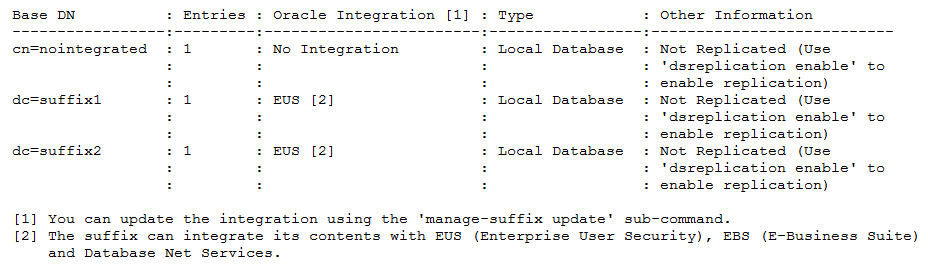
In Example 17-2, information for only suffix dc=suffix2 and only the network group and workflow element are displayed.
To display only a set of suffixes, use the --baseDN argument to specify which suffixes must be displayed. If no --baseDN argument is provided, all suffixes are displayed. You can also use the --advanced argument to display the internal suffixes.
The --listDataToDisplay argument is an informative argument that lists and describes the different allowed values for the argument --dataToDisplay.
Use the --dataToDisplay argument to specify which information is displayed.
Example 17-2 List Suffixes Using BaseDN and Workflow Element Options
$ manage-suffix list --baseDN dc=suffix2 -X --dataToDisplay network-group --dataToDisplay workflow-element -j pwd-file -X -n

Reading Configuration ..... Done.

Base DN     : Wfe [1]   : N.G. [2]
------------:-----------:---------------
dc=suffix2  : userRoot  : network-group

[1] The name of the configuration entity (workflow element) containing the data.
If the data of the data is not stored locally, it returns the name of the first
workflow element associated with the suffix
[2] The name of the network groups that expose the contents of this suffix
In Example 17-3, internal suffixes are displayed using the --advanced option.
Example 17-3 List Suffixes Using the --advanced Option
$ manage-suffix -h localhost -p 4444 -D "cn=directory manager" -j pwd-file -X -n --advanced

Reading Configuration ..... Done.
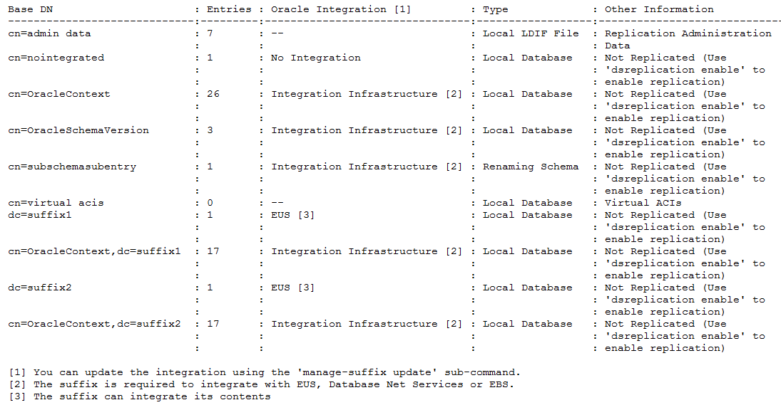
Description of the illustration ''list-suffixes.png''
17.2.4 Modifying a Suffix Configuration
Use the manage-suffix update command to modify an integrated suffix configuration. You can use either the interactive or non-interactive CLI.
In the following example, the manage-suffix update command is used to change the integration property from EUS to generic, which used for integrating either Oracle Database or E-Business Suite. The change is made for both dc=suffix1 and dc=suffix2.
-
To modify an integrated suffix configuration using the non-interactive CLI:
Run the
manage-suffixupdate command. For example:manage-suffix update \ --baseDN dc=suffix1 \ --baseDN dc=suffix2 \ --integration generic \ --hostname host1.local \ --port 4444 \ --bindDN cn=Directory\ Manager \ --bindPasswordFile ****** \ --trustAll \ --no-prompt -
To modify an integrated suffix configuration using the interactive CLI:
Run the manage-update command. For example:
$ manage-suffix update -h localhost -p 4444 -D "cn=directory manager" -j pwd-file

Reading Configuration ..... Done.

Choose the suffixes (separated by commas) to be updated.

    1)  cn=nointegrated
    2)  dc=suffix1
    3)  dc=suffix2
    4)  All

    c)  cancel

Enter one or more choices separated by commas: 2,3

Specify the Oracle components with which the suffixes can integrate.

    1)  Do not update the integration with Oracle components
    2)  No Integration
    3)  Generic: Database Net Services and EBS (E-Business Suite)
    4)  EUS (Enterprise User Security), Database Net Services and EBS
        (E-Business Suite)

    c)  cancel

Enter choice [1]: 3

Choose the network groups (separated by commas) that must expose the suffixes.

    1)  Do not update the network groups
    2)  network-group
    3)  network-group2
    4)  All
    5)  Create a new network group

    c)  cancel

Enter one or more choices separated by commas [1]:

Updating Oracle Integration ....... Done.
17.2.5 Deleting a Suffix Using manage-suffix
Use the manage-suffix delete command to remove a suffix and all of its data. You can use the non-interactive CLI or the interactive CLI.
-
To delete a suffix using the non-interactive CLI:
Run
manage-suffix deletewith thebaseDNargument. For example:manage-suffix delete \ --baseDN dc=nointegration \ --hostname host1.local \ --port 4444 \ --bindDN cn=Directory\ Manager \ --bindPasswordFile ****** \ --trustAll \ --no-prompt -
To delete a suffix using the interactive CLI:
Run the
manage-suffix deletecommand. For example:$ manage-suffix delete -h localhost -p 4444 -D "cn=directory manager" -j pwd-file Reading Configuration ..... Done. Choose the suffixes (separated by commas) to be deleted. 1) cn=nointegrated 2) dc=suffix1 3) dc=suffix2 4) All c) cancel Enter one or more choices separated by commas: 1 You have chosen to delete the suffix 'cn=nointegrated'. Once deleted, the data contained in the suffix will be permanently removed. Do you want to continue? (yes / no) [no]: yes Deleting suffix 'cn=nointegrated' ...... Done.
The non-integrated suffix dc=nointegration is deleted, and its local database workflow element userRoot2 is also deleted. In these examples, local database workflow element userRoot2 will also be deleted if dc=nointegration is the only base DN defined in it.
17.3 Managing the Server Configuration Using ODSM
The Configuration tab of each server instance in ODSM enables you to modify elements of the server configuration. For additional information about managing the configuration that is specific to a proxy server instance, see Part IV, "Configuring Proxy, Distribution, and Virtualization Functionality."
This section provides an overview of the tasks that can be performed on the Configuration tab in ODSM, and covers the following topics:
-
Section 17.3.2, "Using Shortcuts to Configure Objects Using ODSM"
-
Section 17.3.6, "Configuring Connection Handlers Using ODSM"
-
Section 17.3.8, "Modifying the General Server Configuration"
17.3.1 Selecting a Configuration View
The Configuration tab presents two separate views of the server configuration:
-
Naming Contexts. This is the default view, and shows the server configuration in terms of the naming contexts or suffixes configured on that server instance.
-
Core Configuration. This view displays the server configuration in terms of the workflows, workflow elements and server extensions configured on that server instance.
The configuration view that you select determines the items that are available under the Create menu.
17.3.2 Using Shortcuts to Configure Objects Using ODSM
When you create server components using ODSM, you can duplicate an existing component using the Create Like ![]() icon. When you select a component on the configuration tab and click Create Like, a new component with the same configuration is created. You can then edit the properties of the new component to suit your requirements.
icon. When you select a component on the configuration tab and click Create Like, a new component with the same configuration is created. You can then edit the properties of the new component to suit your requirements.
You can also use the Create ![]() icon to create the same type of component as the one you have selected. For example, if you select LDAP Connection Handler in the left hand menu, and click Create, a new, unconfigured LDAP connection handler is created.
icon to create the same type of component as the one you have selected. For example, if you select LDAP Connection Handler in the left hand menu, and click Create, a new, unconfigured LDAP connection handler is created.
Right-clicking on a component in the left hand menu provides a list of actions related to that component. For example, if you right-click LDAP Connection Handler, a drop-down menu is displayed, enabling you to create a new LDAP connection handler, duplicate that LDAP connection handler, or delete the connection handler.
17.3.3 Configuring Suffixes Using ODSM
The following sections describe how to configure suffixes, or naming contexts, using ODSM. For information about using dsconfig to configure suffixes, see Section 17.1.10, "Configuring Suffixes with dsconfig."
17.3.3.1 Creating a Suffix
To configure one or more suffixes using the ODSM interface:
-
Connect to the directory server from ODSM, as described in Section 16.2, "Connecting to the Server Using ODSM."
-
Select the Configuration tab.
-
Select the Naming Contexts view.
-
From the Create menu, select Local Naming Context.
-
In the Naming Context region, perform the following steps:
-
In the Base DN field, type a name for the suffix that you want to create.
-
From the Directory Data Options group, select one of the following options for populating the suffix with data:
Only Create Base Entry creates the database along with the base entry of the suffix. Any additional entries must be added after suffix creation.
Leave Database Empty creates an empty database. The base entries and any additional entries must be added after suffix creation.
Import Generated Sample Data populates the suffix with sample entries.
Specify the number of entries that should be generated in the Number of User Entries field. You can import a maximum of 30,000 sample entries through ODSM. If you want to add more than 30,000 entries, you must use the
import-ldifcommand.
-
-
In the Oracle Components Integration region, select one of the following option to enable the new suffix:
-
No Specific Integration: Select this option, if you do not want to integrate the naming context with Oracle components.
-
Enable for Enterprise User Security (EUS):
To enable a suffix for EUS, you must have at least one LDAP listener with SSL enabled, in addition to the administration listener. The suffix must contain at least one entry (in other words, you must not have selected "Leave Database Empty" in the previous step).
When you select EUS, in addition to creating this suffix, two suffixes are created automatically: "
cn=oracleschemaversion"and"cn=oraclecontext."An EUS workflow element is also added in front of the Local Backend workflow element. Further, a DN renaming workflow element for"cn=schema"is added, so that it can be accessed using the"cn=subschemasubentry"DN. -
Enable for Oracle Database Net Services: Select this option if you want the naming context to store the Database Connect Identifiers.
-
-
In the Network Group region, attach the suffix to at least one network group by performing the following steps:
-
To attach the suffix to an existing network group, select Use Existing and select the required network group from the list.
-
To attach the suffix to a new network group, select Create New and then in the Name field, type a name for the network group you want to create.
You can attach several network groups to the same suffix.
-
-
In the Workflow Element region, attach the suffix to the workflow element by performing either of the following steps:
-
To attach the suffix to an existing workflow element, select Use Existing and then select the required workflow element from the list.
-
To attach the suffix to a new workflow element, select Create New and then in the Name field, type a name for the workflow element you want to create. You can create a Local DB Workflow Element or a Local LDIF Workflow Element.
-
-
Click Create.
The following confirmation message is displayed:
Configuration created successfully.You can configure the tombstone entry purge interval and the tombstone entry lifetime after creating the suffix, in the Local Backend workflow element configuration.
17.3.3.2 Displaying and Editing Suffix Properties
In the Naming Contexts view, the Configuration tab displays all of the suffixes that have been configured on the server.
To display the properties of a configured suffix, follow these steps:
-
Connect to the directory server from ODSM, as described in Section 16.2, "Connecting to the Server Using ODSM."
-
Select the Configuration tab.
-
Select the Naming Contexts view.
-
Expand the Naming Contexts element.
-
Click the suffix whose properties you want to display.
The suffix properties are displayed in the right hand pane.
-
Make any required changes to the suffix configuration.
You can change the network group to which this suffix is attached, and enable the suffix for Enterprise User Security (EUS) or Enable for Oracle Database Net Services.
Note:
If the Oracle Components Integration option was previously configured for the Enable for Enterprise User Security (EUS) or the Enable for Oracle Database Net Services options and if you have made changes in the Oracle Components Integration region, the Configuration Required dialog box appears. Depending on the option you choose, select one of the following:-
Keep Oracle Context: Select this option, if you want to keep the naming context for EUS and Oracle Database Net Service.
-
Delete Oracle Context: Select this option, if you want to delete the naming context for EUS and Oracle Database Net Service.
Click Apply to save your changes.
-
17.3.3.3 Deleting a Suffix
In the Naming Contexts view, the Configuration tab displays all of the suffixes that have been configured on the server.
To delete a suffix, follow these steps:
-
Connect to the directory server from ODSM, as described in Section 16.2, "Connecting to the Server Using ODSM."
-
Select the Configuration tab.
-
Select the Naming Contexts view.
-
Expand the Naming Contexts element.
-
Select the suffix that you want to delete.
-
Click the Delete configuration
 .
.
17.3.4 Configuring Workflow Elements Using ODSM
A workflow element is the key building block of a workflow process. Workflow elements define how client requests that are sent to the server are treated. In a deployment that includes a proxy server, workflow elements are configured for load balancing or distribution. In a deployment that does not include a proxy server, workflow elements are configured directly for each back end.
The following sections describe how to configure workflow elements using ODSM.
For information about using dsconfig to configure workflow elements, see Section 17.1.8, "Configuring Workflow Elements Using dsconfig."
17.3.4.1 Creating a Workflow Element
To create a workflow element using ODSM, follow these steps:
-
Connect to the directory server from ODSM, as described in Section 16.2, "Connecting to the Server Using ODSM."
-
Select the Configuration tab.
-
Select the Core Configuration view.
For more information, see Section 17.3.1, "Selecting a Configuration View."
-
From the Create menu, select Workflow Element and select the type of workflow element that you want to create.
For more information about the various workflow element types, see Section 5.1.3, "Workflow Elements."
-
When the Create page displays for the selected workflow element, configure the properties on that page.
Note:
The properties that you must configure will depend on the type of workflow element that you are creating.All workflow elements require the following basic properties to be configured:
-
Name. Enter a name for the workflow element.
-
Enabled. When you create a workflow element, it is enabled by default. Clear this item to disable the workflow element.
In addition, the following properties must be configured for each corresponding workflow element type:
-
DN Renaming Workflow Element
Property Name Description Client Base DN Specify the base DN that is used by the client application. Source Base DN Specify the base DN that is stored in the LDAP server. Next Workflow Element Select the workflow element that should be next in the workflow. Attribute White List Click Add to select the list of attributes that contain DNs and must be transformed by the renaming operation. Attribute Black List Click Add to select the list of attributes that contain DNs but must not be transformed by the renaming operation. -
EUS Workflow Element
Property Name Description EUS Realm Enter the part of the DIT to which the EUS workflow element applies. Next Workflow Element Select the workflow element that should be next in the workflow. Server Type Select the server containing the EUS user entries. Password Attribute Enter the attribute type that should be used to hold the EUS user passwords. -
EUS Context Workflow Element
Property Name Description EUS Context Enter the DN that contains the Oracle Context. The Oracle Context is a top-level directory entry that contains the data used by any installed Oracle product that uses the directory. EUS Administrator Enter the DN of the administration user. This user will be the uniquemember of the groups created in Oracle Context. Next Workflow Element Select the workflow element that should be next in the workflow. -
Kerberos Authentication Provider Workflow Element
Property Name Description Realm Specify the realm to be used for Kerberos authentication. If you do not specify a realm, then the server attempts to determine the realm from the underlying system configuration. Principal Name Attribute Click Select and specify the Principal Name Attribute. KDC Address Specify the Key Distribution Center (KDC) server address. -
Local DB Workflow Element
Property Name Description Writability Mode Specify whether the back end associated with this workflow element should process write operations. Base DN Specify one or more base DNs for the data that is handled by the back end. Database Properties Specify any specific properties for the database. For a detailed list of these properties, and their values, see "DB Local Backend Workflow Element" in the Configuration Reference for Oracle Unified Directory. Tombstone Configuration Specify how tombstone entries should be handled for the database. For a detailed list of these properties, and their values, see "DB Local Backend Workflow Element" in the Configuration Reference for Oracle Unified Directory. Index Properties Specify the following parameters: -
Index Subtrees: Enable or disable the check box to indicate whether the back end should index subtrees to maintain subtree specific data retaining information on direct and indirect children entries of each parent entry.
-
Local DB Index: Specify the local DB index configuration for the database. For a detailed list of these properties, and their values, see "DB Local Backend Workflow Element" in the Configuration Reference for Oracle Unified Directory.
-
Local DB VLV Index: Specify the local DB VLV index configuration for the database. For a detailed list of these properties, and their values, see "DB Local Backend Workflow Element" in the Configuration Reference for Oracle Unified Directory.
-
-
Local LDIF Workflow Element
Property Name Description Writability Mode Specify whether the back end associated with this workflow element should process write operations. Base DN Specify one or more base DNs for the data that is handled by the back end. Private Backend Specify whether the back end should be considered a private back end, which indicates that it is used for storing operational data rather than user-defined information. LDIF File Enter the path to the LDIF file containing the data for this back end. -
Pass Through Authentication Workflow Element
Basic Properties
Property Name Description User Provider Workflow Element Select the workflow element providing the requested user entry. Authentication Provider Workflow Element Select the workflow element providing the authentication service for the user entry. For example, you can use Kerberos Authentication Provider workflow element or Local DB workflow element as the authentication provider. Advanced Properties
Property Name Description Password Attribute Click Select and specify the password attribute. Save Password on successful bind Enable the check box, if you want the Authentication Provider workflow element to trigger a copy of the password to the User Provider workflow element. Pass Through Authentication Suffix Specify the virtual suffix that is exposed through the PTA workflow element. User Suffix Specify the suffix that contains the user entries on the User Provider workflow element. Authentication Suffix Specify the suffix that contains the authentication entries on the Authentication Provider workflow element. Pass Through Authentication Join Rule Properties
Property Name Description Auth Entry Property Specify the authentication entry property associated with the user entry. User Entry Property Specify the user entry property associated with the authentication entry. For more information, see Section 12.4.4, "Understanding Pass-Through Authentication."
-
Local Memory Workflow Element
Property Name Description Base DN Specify one or more base DNs for the data that is handled by the back end. -
RDN Changing Workflow Element
Property Name Description Next Workflow Element Select the workflow element that should be next in the workflow. Object Class Select the object class type for RDN changing operation. Source RDN Attribute Select the original RDN attribute name from the source directory to be replaced or renamed in Oracle Unified Directory. Client RDN Attribute Select the new RDN attribute name to be used in Oracle Unified Directory. Replace RDN Value Specify whether the original RDN value should be replaced by the new RDN value. It is enabled by default. DN Attributes Click Add to select the list of attributes with DNs on which to perform RDN renaming. -
Transformations Workflow Element
Property Name Description Next Workflow Element Select the workflow element that should be next in the workflow. Entry Matching Filter This is an LDAP filter. If you select this option, then entries will be transformed only if they match this LDAP Filter. Entry Parent Suffixes Optional You can specify a list of suffixes to restrict applying transformation to entries under specific subtrees. If you specify this option, then the entries will be specified only if they are in subtrees rooted at any of these suffixes. Excluded Operations If you specify this option, then the entries will not be transformed during any of the specified operations. Transformations The list of transformations that the Transformations Workflow Element will process. The order in which transformations are listed here does not guarantee the order in which these transformations will be applied when processing a request at runtime.). -
Join Workflow Element
Use the Create Join Workflow Element wizard to create this workflow element, as follows:
-
Configure the following General Properties and then click Next:
Property Name Description Name Enter a name for the workflow element. For example, we-joinEnabled Option is enabled by default, indicating the workflow element is enabled. If necessary, you can disable this element later by returning to this page and clearing the box.
Join Suffix Enter the virtual DN to be exposed by the Join workflow element. For example, dc=joinDN Attributes Optional. Click Add to create a list of attributes (such as manager,memberof, oruniquemember) with DNs on which to perform the join.Populate the virtual attribute ' joinedentrydn' in retrieved entriesOptional. Enable this box to populate the virtual attribute with the entries from secondary participants that were used to form the consolidated entry Note: This information is useful when troubleshooting Join issues.
-
Configure the following Primary Participant properties and click Next.
Property Name Description Participant Name Enter the name of the participant that will contribute information to form the combined joined entry. For example, jp-p1Participant Workflow Element Enter the name of the workflow element that the primary participant will use to attach itself. For example, we-proxy1Participant DN Enter the suffix DN of the participating workflow element or a subtree of that element. For example, dc=com1Enabled Operations Optional. Click the menu button to view a list of operations, which include: Add, Bind, Compare, Delete, Modify, Modify DN, and Search. -
Select one or more boxes to enable operations.
-
Clear the boxes to disable operations.
Criticality Specify one of the following criticality flags for the join workflow element: -
true (default): Indicates the participant is critical.
If the participant fails to return a result due to an operation error, then the overall operation fails and an error message results.
-
false: Indicates that a failure to perform an operation in the participant is not critical to the overall result.
-
partial: Indicates the participant is partially critical.
If the participant fails to return a result due to an operation error, then the application can notify its own users that partial results were obtained, the Join workflow element returns partial results, but also returns an error message.
Join Condition This field is blank by default, indicating that no join condition is defined. All entries that satisfy the original search filter will be considered for a join. To restrict the entries to be joined, click Define to access the Filter Builder dialog where you configure a filter:
-
Select an attribute name from the left menu.
-
Select a matching rule from the middle menu.
-
Enter a value to match.
-
Click Add to create another filter.
-
When you are finished creating filters, click OK.
Entries that do not satisfy the specified conditions are returned as is, with no join done on them.
Note: For information, see Section 12.5.1.6, "Understanding the Join Condition."
Attribute Storage Enable one of the following to specify which attributes the Join participant can store on the target directory: -
All attributes are storable (default): All attributes can be stored.
-
Only the selected attributes are storable: Click Add and then click the search icon
 to select one or more attributes from the Attribute Picker dialog. Only the selected attributes can be stored.
 -
All except the following attributes are storable: Click Add and then click the search icon
to select one or more attributes from the Attribute Picker dialog. All attributes can be stored except for the selected attributes.
Attribute Retrieval Enable one of the following to specify which attributes the Join participant can retrieved from the target directory: -
All attributes are retrievable (default): All attributes can be retrieved.
-
Only the selected attributes are retrievable: Click Add and then click the search icon
to select one or more attributes from the Attribute Picker dialog. Only the selected attributes can be retrieved. -
All except the following attributes are retrievable: Click Add and then click the search icon
to select one or more attributes from the Attribute Picker dialog. All attributes can be retrieved except for the selected attributes.
-
-
The Secondary Participant page is displayed, and it contains a menu with options that enable you to View, Create, Modify, or Remove participants.
To add one or more secondary participants, click Create and configure the properties on the Create Secondary Participant page. These properties are essentially the same as those you configured for the Primary Participant, except for the following:
Property Name Description Joiner Type Click the button and select one of the following joiner types from the menu: -
Many to one:
-
One to many
-
One to one (default)
-
Shadow
For a description of these join relationships, see Section 12.5.1.5, "Understanding Joiner Types."
When you are finished adding participants, click Next.
-
-
Configure the following Participant Relations Properties to define Join Rule relations and to view or move Bind Participants. You can also view the join relations between participants in a tree structure. When you are finished, click Next.
Property Name Description Define Join Rule Relations Click Define to open the Filter Builder dialog, where you can specify filter criteria for a join rule. Note: You might have to enlarge the browser window to access this button. To specify the filter criteria:
-
Select the leftmost menu button to choose an attribute name for the first participant.
-
Click the next button to choose a matching rule.
-
In the next field, enter or choose the other participant name.
-
Select the rightmost button to choose an attribute name for the second participant.
Click the plus sign icon to add additional filter rules. When you are finished, click OK.
Participant Relations Use this area to view the join relations between participants. Bind Participants View or move the participants up or down in the table. -
-
Use the following Network Group properties to associate this workflow element with a network group. When you are finished, click Next.
Property Name Description Associate this workflow element with a Network Group Enable this box to associate this workflow element with a network group and workflow. When you enable the box, the other features on this page become active. Select the network group to which the workflow element must be attached Enable the network-group box to attach the workflow element to that group. Click Create Network Group to open the Create Network Group dialog. Enter a new name and click Create.
Create New Workflow Enter a name in the field to create a new workflow. -
When the Summary page is displayed, click back through all of the pages to review the property settings. If necessary, make any necessary changes.
-
If you are satisfied with the configuration, click Create to create the Join workflow element.
-
-
-
Click Create.
The following confirmation message is displayed:
Workflow Element created successfully.
17.3.4.2 Displaying and Editing Workflow Element Properties
To display or modify the properties of an existing workflow element, follow these steps:
-
Connect to the directory server from ODSM, as described in Section 16.2, "Connecting to the Server Using ODSM."
-
Select the Configuration tab.
-
Select the Core Configuration view.
For more information, see Section 17.3.1, "Selecting a Configuration View."
-
Expand the Core Configuration element.
-
Expand the Workflow Elements element.
-
Click the workflow element that you want to view, or modify.
The properties of the workflow element are displayed in the right hand pane
-
The properties that you can edit depend on the type of workflow element that is configured.
-
Click Apply to save your changes.
17.3.4.3 Deleting a Workflow Element
To delete an existing workflow element, follow these steps:
-
Connect to the directory server from ODSM, as described in Section 16.2, "Connecting to the Server Using ODSM."
-
Select the Configuration tab.
-
Select the Core Configuration view.
For more information, see Section 17.3.1, "Selecting a Configuration View."
-
Expand the Core Configuration element.
-
Expand the Workflow Elements element.
-
Click the workflow element that you want to delete and click the Delete configuration
. -
Click OK to confirm the deletion.
17.3.5 Configuring Workflows Using ODSM
A workflow is defined by a naming context, or suffix, and a workflow element that define how Oracle Unified Directory should handle an incoming request. A workflow must be registered with at least one network group, but can be attached to several network groups.
For more information about workflows, workflow elements and the other components of Oracle Unified Directory, see Section 5.1, "Oracle Unified Directory Components."
The following sections describe how to configure workflows using ODSM. For information about configuring workflows using dsconfig, see Section 17.1.7, "Configuring Workflows Using dsconfig."
17.3.5.1 Creating a Workflow
To create a workflow using ODSM, follow these steps:
-
Connect to the directory server from ODSM, as described in Section 16.2, "Connecting to the Server Using ODSM."
-
Select the Configuration tab.
-
Select the Core Configuration view.
For more information, see Section 17.3.1, "Selecting a Configuration View."
-
From the Create menu, select Workflow.
-
In the Workflow Properties region, enter the following information:
-
In the Name field, type a name for the workflow that you want to create.
-
Select the Enabled check box if you want this workflow to be enabled.
Deselect this check box if you do not want to enable the workflow at this stage.
-
-
In the Base DN field, enter the naming context that will be accessible through this workflow.
-
Select the Workflow Element with which this workflow should be associated.
The workflow element must already exist before you create the workflow.
-
Select True, False, or Partial depending on whether the workflow is critical enough to fail a search operation involving multiple workflows and if the operation fails on this workflow.
-
Select the Use Virtual ACIs check box if you want to define a different storage repository for the ACI data associated to all entries managed by the workflow.
-
If the Use Virtual ACIs check box is selected then specify the name of the stripe to be used in the Virtual ACI storage to maintain ACI data for this workflow.
-
Click Create.
The following confirmation message is displayed:
Workflow created successfully.
17.3.5.2 Displaying and Editing Workflow Properties
In the Core Configuration view, the Configuration tab displays all of the workflows and workflow elements that have been configured on the server.
To display the properties of a configured workflow, follow these steps:
-
Connect to the directory server from ODSM, as described in Section 16.2, "Connecting to the Server Using ODSM."
-
Select the Configuration tab.
-
Select the Core Configuration view.
For more information, see Section 17.3.1, "Selecting a Configuration View."
-
Expand the Workflows element.
-
Click the workflow whose properties you want to display.
The workflow properties are displayed in the right hand pane.
-
Make any required changes to the suffix configuration.
You can disable the workflow, or change the workflow element with which this workflow is associated.
Click Apply to save your changes.
17.3.5.3 Deleting a Workflow
You use ODSM to delete a workflow only if that workflow is not referenced by any network group.
To delete a workflow:
-
Connect to the directory server from ODSM, as described in Section 16.2, "Connecting to the Server Using ODSM."
-
If the workflow is referenced by a network group, modify the properties of the network group to remove that workflow.
For more information, see Section 17.3.7.2, "Modifying a Network Group."
-
Select the Configuration tab.
-
Select the Core Configuration view.
For more information, see Section 17.3.1, "Selecting a Configuration View."
-
Expand the Workflows element.
-
Select the workflow that you want to delete and click the Delete configuration
. -
Click OK to confirm the deletion.
17.3.6 Configuring Connection Handlers Using ODSM
Connection handlers are responsible for accepting connections from clients, reading and parsing requests submitted by the clients, ensuring that they are processed by the server, and sending the corresponding responses back to the client. A connection handler manages all communication with the client and therefore needs to implement support for the associated protocol.
The following sections describe how to configure connection handlers using ODSM. For information about configuring connection handlers using dsconfig, see Section 17.1.5, "Configuring Connection Handlers Using dsconfig."
17.3.6.1 Creating a Connection Handler
To create a connection handler:
-
Connect to the directory server from ODSM, as described in Section 16.2, "Connecting to the Server Using ODSM."
-
Select the Configuration tab.
-
From the Create menu, select Connection Handler.
-
Select the type of connection handler that you want to create:
-
LDAP. This connection handler is used to interact with clients using LDAP. It provides full support for LDAPv3 and limited support for LDAPv2.
-
LDAPS. This connection handler is used to interact with clients using LDAP over SSL.
-
LDIF. This connection handler is used to process changes in the server using internal operations.
-
JMX. This connection handler allows interactions with clients using the Java Management Extensions (JMX) framework and the Remote Method Invocation (RMI) protocol.
-
SNMP. This connection handler is used to process SNMP requests to retrieve monitoring information described by MIB 2605. The supported SNMP protocols are SNMP V1, V2c and V3.
-
-
Enter the properties to configure the connection handler in the right hand pane.
The configurable properties will depend on the type of connection handler you have selected. For a comprehensive list of all configurable properties, and their allowed values, see "The Connection Handler Configuration" in the Configuration Reference for Oracle Unified Directory.
-
When you have configured the required properties for your specific connection handler type, click Create.
The following confirmation message is displayed:
Connection Handler created successfully.
17.3.6.2 Modifying a Connection Handler
To view or modify connection handler properties:
-
Connect to the directory server from ODSM, as described in Section 16.2, "Connecting to the Server Using ODSM."
-
Select the Configuration tab.
-
Expand the General Configuration element.
-
Expand the Connection Handlers element.
-
Click the connection handler whose properties you want to modify.
The properties are displayed in the right hand pane.
For a comprehensive list of all configurable properties, and their allowed values, see "The Connection Handler Configuration" in the Configuration Reference for Oracle Unified Directory.
-
Change the required properties and click Apply.
17.3.6.3 Deleting a Connection Handler
To delete an existing connection handler:
-
Connect to the directory server from ODSM, as described in Section 16.2, "Connecting to the Server Using ODSM."
-
Select the Configuration tab.
-
Expand the General Configuration element.
-
Expand the Connection Handlers element.
-
Click the connection handler that you want to delete and click the Delete configuration
. -
You are prompted to confirm the deletion. Click OK.
17.3.7 Configuring Network Groups Using ODSM
Network groups are the entry point of all client requests that are handled by an Oracle Unified Directory server. The properties of a network group indicate how client requests are directed.
The following sections describe how to configure network groups using ODSM. For information about configuring network groups using dsconfig, see Section 17.1.6, "Configuring Network Groups Using dsconfig."
17.3.7.1 Creating a Network Group
To create a network group using ODSM, follow these steps:
-
Connect to the directory server from ODSM, as described in Section 16.2, "Connecting to the Server Using ODSM."
-
Select the Configuration tab.
-
From the Create menu, select Network Group.
-
Configure the network group by using the following properties, available in the right-hand pane.
-
Name. Enter a name for the network group.
-
Enabled. Select or deselect this check box to enable or disable the network group. If you disable a network group, then no client requests can be handled by that network group. If you disable the only configured network group, then you effectively stop client applications from accessing the back end.
-
Priority. If you have multiple network groups, specify a priority for this network group. Client requests are handled by the network group with the highest priority, for which the criteria are met. The highest priority a network group can have is 0.
-
Workflow. Click the Add (
 ) to add one or more workflows that can be accessed through this network group.
 -
Root DSE to Expose. Select the Root DSE that you want this network group to expose. You can expose the Root DSE of the local server, the Root DSE stored in a remote server, or the Root DSE defined in a local file.
Click Other and select one of the following option:
-
Root DSE Defined in LDIF File: Enter the path of the LDIF file containing the Root DSE. The server must have access to this file.
-
Root DSE of a Remote Server: Enter the following parameters:
Host Name: Enter the host name of the remote server.
Ports Available: Enter the LDAP port, LDAPS port, or LDAP and LDAPS ports of the remote server.
Trust All: Select this check box to trust all the certificates presented by the remote server.
Trust Manager: Select the trust manager that the server will use when connecting to the LDAPS ports of the remote server to forward requests.
-
-
Security Mandatory. Select this option if you require clients to use a secure connection to access this network group. By default, a secure connection is not required.
-
Allowed auth method. Specify the authentication method/s that are allowed between the client and the network group.
-
Allowed protocol. Specify the protocol/s that are allowed for client connections. If you do not specify a protocol, all protocols are allowed.
-
Allowed BindDN. Click the Add to add one or more bind DNs that are allowed to connect to this network group. Click the Delete (
 ) to remove the bind DNs that should not be accepted by the network group.
 -
Allowed Client. Click the Add to add one or more clients that are authorized to access this network group. Clients can be expressed by their IP addresses or names, or by a subnet mask. If no allowed client list is provided, all clients are allowed, unless they are specifically listed on the denied client list.
-
Denied Client. Click the Add to add one or more clients that are prohibited from accessing this network group. Clients can be expressed by their IP addresses or names, or by a subnet mask. If no denied client list is provided, all clients are allowed, unless a limitation is set using the allowed client list.
-
QoS Policy. Select a quality of service policy for this network group. For more information, see Section 17.1.6.3, "Creating a Network Group Quality of Service Policy."
-
-
When you have configured the required properties for the network group, click Create.
The following confirmation message is displayed:
Network Group created successfully.
17.3.7.2 Modifying a Network Group
You can view or modify the properties of a network group, as follows:
-
Connect to the directory server from ODSM, as described in Section 16.2, "Connecting to the Server Using ODSM."
-
Select the Configuration tab.
-
Expand the General Configuration element.
-
Expand the Network Groups element.
-
Select the network group whose properties you want to modify.
The properties of the network group are displayed in the right hand pane
-
Change the required properties and click Apply.
For an explanation of each of the configured properties, see Section 17.3.7.1, "Creating a Network Group."
17.3.7.3 Deleting a Network Group
To delete an network group, follow these steps:
-
Connect to the directory server from ODSM, as described in Section 16.2, "Connecting to the Server Using ODSM."
-
Select the Configuration tab.
-
Expand the General Configuration element.
-
Expand the Network Groups element.
-
Click the network group that you want to delete and click the Delete configuration
. -
You are prompted to confirm the deletion. Click OK.
17.3.8 Modifying the General Server Configuration
To modify elements of the general server configuration:
-
Connect to the directory server from ODSM, as described in Section 16.2, "Connecting to the Server Using ODSM."
-
Select the Configuration tab.
-
Select the General Configuration element.
The properties are displayed in the right hand pane.
-
You can modify the following properties:
-
Root DSE Properties
-
Work Queue Properties
-
Access Control Groups
-
Data Encryption
-
Number of Worker Threads
Server General Properties
-
Default Password Policy: Specify the name of the password policy, if the entries do not have an alternate password policy,
-
Etime Resolution: Select a resolution for operation elapsed processing time measurements. The default value is Milliseconds.
-
Idle Time Limit: Specify the maximum duration a client connection may remain established since its last completed operation. If you specify
0 secondsas the value, then no idle time limit is enforced. -
Max Allowed Client Connections: Specify the maximum number of client connections you want to establish at any given time. A value of 0 indicates that unlimited client connection is allowed.
-
Maintain Authenticated Users: Select the check box, if you want the server to maintain authenticated users.
-
Reject Unauthenticated Requests: Select the check box, if you want the directory server to reject any request (other than bind or StartTLS requests) received from a client that has not yet been authenticated, whose last authentication attempt was unsuccessful, or whose last authentication attempt used anonymous authentication.
-
Size Limit: Enter a value to specify the maximum number of entries that can be returned to the client during a single search operation. A value of 0 indicates that no size limit is enforced. This is the default server wide limit, but it may be overridden on a per user basis using the
ds-rlim-size-limitoperational attribute. -
Writability Mode: Specify the type of write operations the Directory Server can process.
Root DSE Properties
-
Show Operational Attributes: Select this check box, if you want all attributes in the root DSE to be treated like user (non operational) attributes (and therefore returned to clients by default) regardless of the Directory Server schema configuration.
-
Subordinate Base DNs: Specify the set of base DNs used for singleLevel, wholeSubtree, and subordinateSubtree searches based at the root DSE.
Work Queue Properties
-
Number of Worker Threads: Specify the number of worker threads to be used for processing operations placed in the queue. If the value is increased, the additional worker threads are created immediately. If the value is reduced, the appropriate number of threads are destroyed as the operations complete processing.
-
Click the Dynamically Handled by Server check box, if you want the server to determine the number of worker threads at run time.
-
Maximum Work Queue Capacity: Specify the maximum number of queued operations that can be in the work queue at any given time. If the work queue is already full and additional requests are received by the server then the server front end and possibly the client will be blocked until the work queue has available capacity.
Data Encryption
-
Check Enabled check box, to enable encryption.
-
Encryption Algorithm: Select the algorithm value for encryption. The default value is AES_128.
-
Encrypted Attributes: Define the attributes for encryption.
If you enable Data Encryption, then you must add the attribute names.
-
Suffixes to Apply Encryption: Define the suffix for encryption.
-
If you do not define a suffix, then encryption is applied to all available suffixes.
-
If you define a suffix, then encryption is only applied to the defined suffix.
-
Click Apply to save your changes.
Note:
Modifying data encryption configuration may cause the indexes to be invalid. If any of the selected attributes are indexed then you must rebuild the indexes for these attributes as described in Appendix A, "rebuild-index."For a comprehensive list of the configurable properties, and their allowed values, see "Global Configuration" in the Configuration Reference for Oracle Unified Directory.
-
17.4 Managing Administration Traffic to the Server
Connection handlers are responsible for handling all interaction with client applications, including accepting connections, reading requests, and sending responses.Oracle Unified Directory includes a special connection handler, the administration connector, to manage administration traffic to the server. The administration connector enables the separation of user traffic and administration traffic to simplify monitoring, and to ensure that administrative commands take precedence over commands that manipulate user data.
This section describes how administration traffic is handled, and covers the following topics:
17.4.1 Understanding the Administration Connector
The administration connector is based on the LDAP protocol and uses LDAP over SSL by default. All command-line utilities that access the administrative suffixes use the administration connector. This includes the following commands:
-
backup -
dsconfig -
dsreplication -
export-ldif -
import-ldif -
manage-account -
manage-tasks -
restore -
status -
stop-ds -
uninstall
The administration connector is always present and enabled. You cannot disable or delete the connector but you can use dsconfig to manipulate the following properties of the connector:
-
listen-address. The address on which the server listens for administration traffic. -
listen-port. The default port of the administration connector is 4444. You can change this port during setup if required. If you use the default port, you do not need to specify a port when running the administration commands (the default port is assumed). If you change the port, you must specify the new port when running the administration commands.If you have multiple directory server instances running on the same host, you will have specified multiple separate administration listen ports during setup. In this case, for the server instances whose administration connectors do not use the default listen port (4444), you will need to specify the port when running the administration commands.
-
Security-related properties. Traffic using the administration connector is always secured. As with the LDAPS connection handler, the administration connector is configured with a self-signed certificate (
admin-cert) during server setup. This self-signed certificate is generated the first time the server is started. You can manage the administration connector certificate using external tools, such askeytool.The security-related properties of the administration include the following:
-
ssl-cert-nickname -
ssl-cipher-suite -
key-manager-provider -
trust-manager-provider
When you run the administration commands, you are prompted about how you want to trust the certificate. If you run the administration commands in non-interactive mode, you must specify the
-Xor--trustAlloption to trust the certificate, otherwise the command will fail. -
17.4.2 Accessing Administrative Suffixes
The administrative suffixes include the following:
-
cn=config -
cn=monitor -
cn=tasks -
cn=backups -
cn=ads-truststore -
cn=schema -
cn=admin data
In general, direct LDAP access to the administrative suffixes (using the ldap* utilities) is discouraged, with the exception of the cn=monitor suffix. In most cases, it is preferable to use the dedicated administrative command-line utilities to access these suffixes.
If you must use the ldap* commands to access the administrative suffixes, you must use the administration connector port (with the --useSSL or -Z option). Using the administration connector ensures that monitoring data is not polluted and that server administration takes precedence over user traffic. The same restriction applies if you are accessing the administrative suffixes using an LDAP browser.
17.4.3 Configuring the Administration Connector
The following example displays the default properties of the administration connector, and changes the listen port of the connector to 5555.
-
View the default properties of the administration connector, using the
dsconfigcommand.$ dsconfig -h localhost -p 4444 -D "cn=directory manager" -j pwd-file -X -n \ get-administration-connector-prop
The output is similar to the following.
Property               : Value(s)
-----------------------:---------------
key-manager-provider   : Administration
listen-address         : 0.0.0.0
listen-port            : 4444
ssl-cert-nickname      : admin-cert
ssl-cipher-suite       : -
trust-manager-provider : Administration
-
Change the listen port, using the
dsconfigcommand.$ dsconfig -h localhost -p 4444 -D "cn=directory manager" -j pwd-file -X -n \ set-administration-connector-prop --set listen-port:5555
Note:
You must restart the server for changes to this property to take effect.
17.4.4 Modifying Key Manager and Trust Manager Properties for the Administration Connector
The administration connector is an LDAPS connector. As with all SSL-based connectors, the administration connector requires a key manager and trust manager.
Oracle Unified Directory provides a dedicated key manager and trust manager for the administration connector, which are enabled by default. You can change the properties of the default administration key manager and trust manager. For more information, see Section 26.2, "Configuring Key Manager Providers" and Section 26.3, "Configuring Trust Manager Providers."
17.5 Configuring Commands As Tasks
You can use command-line utilities to schedule tasks that run within the directory server and perform their functions locally. These scheduled tasks support options used to connect to the directory server to interact with the task back end.
This section includes the following topics:
17.5.1 Commands That Can Schedule Tasks
The following utilities can schedule tasks:
-
import-ldif -
export-ldif -
backup -
restore -
stop-ds -
stop-ds --restart -
rebuild-index -
dsreplication purge-historical
For a proxy server, only the stop-ds command can be scheduled to run as a task.
17.5.2 Controlling Which Tasks Can Run
You can control the tasks that can be run by setting the allowed-tasks advanced global configuration property. By default, all tasks supported by the tasks back end are allowed. To prevent a task from being run, remove its value from the allowed-tasks property. For example, to prevent the server from being stopped using a task, run the following command:
$ dsconfig -h localhost -p 4444 -D "cn=directory manager" -j pwd-file -X -n \
  set-global-configuration-prop --remove \
  allowed-task:org.opends.server.tasks.ShutdownTask
17.5.3 Scheduling and Configuring Tasks
The procedures in this section indicate how to schedule a task, how to configure task notification, and how to configure task dependencies. All of the examples in this section assume that the commands are being run on the local host, using the default administration port (4444), and the local certificate configuration. If you run the commands remotely, you might need to specify the certificate parameters. For more information, see Section 17.4, "Managing Administration Traffic to the Server."
This section describes procedures to schedule and configure tasks, and contains the following topics:
17.5.3.1 Scheduling a Task
To schedule a task, invoke the required utility with the options used to connect to the directory server, an optional start time, and any options that will be used as arguments for the task execution.
If the -t or --start option is provided, the utility exits immediately after scheduling the task. To schedule a task for immediate execution and have the utility exit immediately after scheduling the task, specify 0 as the value for the start time.
If the -t or --start option is omitted, the utility schedules the task for immediate execution and tracks the task's progress, printing log messages as they are available and exiting when the task has completed.
Schedule the export-ldif task to start at 12:15 on September 24th, 2009.
$ export-ldif -D "cn=directory manager" -j pwd-file \
  -l /ldif-files/example.ldif --start 20090924121500 -n userRoot
17.5.3.2 Scheduling a Recurring Task
To schedule a recurring task, invoke the required utility with the options used to connect to the directory server, specifying the recurring task schedule, and any options that will be used as arguments for the task execution. The following commands can be scheduled as recurring tasks:
-
import-ldif -
export-ldif -
backup -
restore -
rebuild-index -
dsreplication purge-historical
The --recurringTask option specifies a recurring task schedule that is used by the task scheduler to determine when and how often a recurring task should run. The pattern used to specify the schedule is based on UNIX crontab(5) scheduling patterns and rules and includes the following five integer pattern fields, separated by blank spaces:
-
Minute [0,59]
-
Hour [0,23]
-
Day of the month [1,31]
-
Month of the year [1,12]
-
Day of the week [0,6] (with 0=Sunday)
Each of these patterns can be either an asterisk (meaning all valid values), an element, or a list of elements separated by commas. An element is either a number or two numbers separated by a dash (meaning an inclusive range).
The task scheduler spawns regular task iterations according to the specified schedule.
Schedule the task using the --recurringTask option.
The following command schedules a backup task to execute at the beginning of every hour.
$ backup -D "cn=directory manager" -j pwd-file --recurringTask \
  "00 * * * *" --backupDirectory /example/backup --backUpAll --backupID "Hourly Backup"
The following example shows an export task that is scheduled to run every 15 minutes, every Sunday.
$ export-ldif -D "cn=directory manager" -j pwd-file --recurringTask \
  "0,15,30,45 * * * 0" -l PATH/export-recurring.ldif -n userRoot
Recurring Export task  ExportTask-a614e45d-6ba5-4c29-a8e1-d518c20e46ab scheduled
successfully
17.5.3.3 Configuring Task Notification
The task scheduling options of a utility enable you to notify an administrator when a task completes or if an error occurs during the task's execution. To use the notification facility, an SMTP server must be configured for the directory server.
-
Specify an SMTP server by setting the
smtp-serverglobal configuration property.The following command configures the SMTP server named
mailserver.example.com:$ dsconfig -h localhost -p 4444 -D "cn=directory manager" -j pwd-file -X -n \ set-global-configuration-prop --set smtp-server:mailserver.example.com
-
Use the
completionNotifyanderrorNotifyoptions to specify the email address to which the task notification should be sent.The following command schedules a
backuptask and specifies thatadmin@example.comshould be notified when the task completes, or when an error occurs:$ backup -D "cn=directory manager" -j pwd-file -a -d /tmp/backups \ --start 20080924121500 --completionNotify admin@example.com \ --errorNotify admin@example.com Backup task 20080924121500 scheduled to start Sep 24, 2008 12:15:00 PM SAST
17.5.3.4 Configuring Task Dependencies
Certain tasks might require that another task be completed before the task begins. The task dependency options of a utility enable you to specify that the task depends on another task, and what the task should do should the other task fail.
Schedule the task and specify the dependency and failedDependencyAction.
The following example schedules a backup task that depends on another task, and specifies that the backup should be canceled should the other task fail:
$ backup -D "cn=directory manager" -j pwd-file -a -d /tmp/backups \
  --start 2008102914530410 --dependency 20080924121500 \
  --failedDependencyAction cancel
Backup task 2008102914530410 scheduled to start Oct 29, 2008 14:53:04 PM SAST
17.5.4 Managing and Monitoring Scheduled Tasks
The manage-tasks utility can be used to obtain a list of scheduled tasks, to display task status, and to cancel scheduled tasks. The following procedures provide examples of managing scheduled tasks:
17.5.4.1 Viewing Information About Scheduled Tasks
-
Display a summary of all scheduled tasks.
$ manage-tasks -D "cn=directory manager" -j pwd-file -n -s
ID                Type    Status
------------------------------------------------
2008100912550010  Backup  Completed successfully
2008100912554710  Backup  Completed successfully
2008100912560510  Backup  Waiting on start time
2008100912561410  Backup  Waiting on start time
-
Display additional information on a particular task, specified by its task ID.
$ manage-tasks -D "cn=directory manager" -j pwd-file -n -i 2008100912550010

Task Details
------------------------------------------------------
ID                        2008100912550010
Type                      Backup
Status                    Completed successfully
Scheduled Start Time      Immediate execution
Actual Start Time         Oct 9, 2008 12:55:00 PM SAST
Completion Time           Oct 9, 2008 12:55:01 PM SAST
Dependencies              None
Failed Dependency Action  None
Email Upon Completion     None Specified
Email Upon Error          None Specified

Backup Options
----------------------------
Backup All        true
Backup Directory  ../backups

Last Log Message
------------------------------------------------------------------------------
[09/Oct/2008:12:55:01 +0200] severity="NOTICE" msgCount=4 msgID=10944795
message="The backup process completed successfully"
17.5.4.2 Canceling a Scheduled Task
Run the manage-tasks utility with the -c or --cancel option.
The following command cancels a particular task, specified by its task ID:
$ manage-tasks -D "cn=directory manager" -j pwd-file -n -c 2008100912561410
17.5.4.3 Canceling a Recurring Task
You can cancel an entire recurring task, in which case both the recurring task and its next scheduled iteration are canceled. Alternatively, you can cancel only the next scheduled task iteration, in which case future recurring task iterations will be spawned by the task scheduler.
-
Use the manage-tasks command to display the summary of scheduled tasks.
$ manage-tasks -D "cn=directory manager" -j pwd-file -n -s

 ID                                             Type    Status
----------------------------------------------------------------------------
 Hourly Backup                                  Backup  Recurring
 Hourly Backup - Wed Jan 14 13:00:00 SAST 2009  Backup  Waiting on start time
-
Run the
manage-tasksutility with the-cor--canceloption.-
Cancel the entire recurring task by specifying its task ID.
$ manage-tasks -D "cn=directory manager" -j pwd-file -n -c "Hourly Backup"
Task Hourly Backup canceled
-
Cancel the next scheduled task by specifying its task ID.
$ manage-tasks -D "cn=directory manager" -j pwd-file -n \
  -c "Hourly Backup - Wed Jan 14 13:00:00 SAST 2009 "
Task Hourly Backup - Wed Jan 14 13:00:00 SAST 2009  canceled
-
17.6 Deploying and Configuring the DSML Gateway
The Directory Services Markup Language (DSML) is a SOAP-based mechanism that can communicate with directory servers using an XML-based representation instead of the LDAP protocol. Oracle Unified Directory 11g Release 2 PS1 (11.1.2.1.0) supports the use of DSML through a web application that acts as a DSML-to-LDAP gateway, in which clients communicate with the gateway using DSML, but the gateway communicates with the directory server through LDAP.
This section describes how to configure and deploy the DSML gateway, and contains the following topics:
17.6.1 Deploying the DSML Gateway
The DSML gateway can be deployed like any other web application, in most common application containers. This section describes how to deploy the DSML gateway in Oracle WebLogic Server.
To deploy the DSML Gateway in Oracle WebLogic Server, you must perform the following steps:
-
Ensure that you have installed Oracle WebLogic Server, as described in "Installing Oracle WebLogic Server" in Oracle Fusion Middleware Installing Oracle Unified Directory.
-
Configure the WebLogic Server for the DSML Gateway as described in Section 17.6.1.1, "Configuring WebLogic Server for the DSML Gateway."
-
Deploy the DSML Gateway WAR file, as described in Section 17.6.1.2, "Deploying the DSML Gateway WAR File."
17.6.1.1 Configuring WebLogic Server for the DSML Gateway
To configure a WebLogic Server for the DSML Gateway:
-
Run the configuration wizard from the following location:
OUD_BASE_LOCATION_HOME
/wlserver_10.3/common/bin/config.sh -
On the Welcome screen, select Create a new WebLogic domain and click Next.
-
On the Select Domain Source screen, accept the default selection (Basic WebLogic Server Domain) and click Next.
-
On the Specify Domain Name and Location screen, type a domain name and specify its location.
A new WebLogic domain is created in this location. The DSML gateway will be deployed into this domain.
-
On the Configure Administrator User Name and Password screen, type a name and password for the user who will administer this domain.
The password must be at least eight characters and must contain at least one number or special character. Confirm the password and click Next.
Make a note of these details as you will need them to start or restart the WebLogic domain.
-
On the Configure Server Start Mode screen, select Production Mode.
Select a valid JDK (at least JDK 7) and click Next.
-
On the Optional Configuration screen, click Next.
-
On the Configuration Summary screen, verify the domain details and click Create.
-
On the Creating Domain Screen, click Done.
-
Set the Java options for the WebLogic Server.
$ export JAVA_OPTIONS=-Djavax.xml.soap.MessageFactory=weblogic.xml.saaj.MessageFactoryImpl
If you do not set the Java options, an error will be returned.
-
Set the
enforce-valid-basic-auth-credentialsflag in the configuration file of the WebLogic domain (DOMAIN_HOME/config/config.xml, whereDOMAIN_HOMEis the domain that you created in Step 4.For example, edit the file OUD_BASE_LOCATION_HOME
/user_projects/domains/base_domain/config/config.xmlby adding the following line to thesecurity-configurationelement:<enforce-valid-basic-auth-credentials>false</enforce-valid-basic-auth-credentials>For more information, see
http://download.oracle.com/docs/cd/E12840_01/wls/docs103/security/thin_client.html#understanding_basic_atn. -
Start the WebLogic Server by running DOMAIN_HOME
/bin/startWebLogic.sh(whereDOMAIN_HOMEis the domain that you created in Step 4.For example:
OUD_BASE_LOCATION_HOME
/user_projects/domains/base_domain/bin/startWebLogic.sh -
Deploy the DSML Gateway WAR file, as described in the following section.
17.6.1.2 Deploying the DSML Gateway WAR File
To deploy the DSML Gateway WAR file:
-
Create a
DSMLdirectory in the addons directory and change to that directory.$ cd OUD_BASE_LOCATION_HOME/ORACLE_HOME/addons $ mkdir DSML $ cd DSML -
Explode the DSML gateway WAR file.
$ jar xvf ../OUD-DSML.zip
-
Edit the DSML configuration, if required.
The
WEB-INF/web.xmlfile includes initialization parameters that can be used to specify the address (in theldap.hostparameter) and port number (in theldap.portparameter) of the directory server to which DSML requests should be forwarded.By default, the DSML gateway is configured to communicate with a directory server on the same system, that is,
localhost) on port389. If you must change the host address and port number, edit theweb.xmlfile and restart the web container. -
In a browser window, connect to the WebLogic Administration Console (for example,
http://hostname:7001/console), where hostname is the host on which WebLogic Server is running.Use the administrator user name and password that you established in Step 5 of the preceding procedure.
-
Follow the WebLogic Server Documentation to install a Web application (
http://download.oracle.com/docs/cd/E12840_01/wls/docs103/ConsoleHelp/taskhelp/web_applications/InstallWebApplications.html).-
In step 4 of the procedure, provide the path to the exploded application (OUD_BASE_LOCATION_HOME/ORACLE_HOME
/addons/DSML). -
In step 6 of the procedure, select Install this deployment as an application.
-
Accept the default values for the other steps.
-
-
On the left panel of the Administration Console, click Deployments.
-
Select the check box next to the DSML application and click Start then Servicing all requests.
-
On the Start Deployments panel, click Yes.
-
The DSML application is now deployed and available for use.
17.6.2 Confirming the DSML Gateway Deployment
After the DSML gateway has been deployed and configured, you can communicate with it using any DSMLv2 client. The following sections describe two ways to accomplish this:
-
Section 17.6.2.1, "Confirming the DSML Gateway Deployment Using JXplorer"
-
Section 17.6.2.2, "Confirming the DSML Gateway Deployment Using the Directory Server Resource Kit"
17.6.2.1 Confirming the DSML Gateway Deployment Using JXplorer
The JXplorer tool is a Java-based LDAP browser that can be used to browse, search, and edit the contents of an Oracle Unified Directory instance. This tool can communicate using both LDAP and DSML. Although JXplorer's DSML support does not allow authentication (and therefore is restricted to the set of operations available to anonymous users), it is still possible to use it to verify that the DSML gateway is functioning as expected.
You can download JXplorer, and the accompanying documentation, at jxplorer.org.
To confirm a DSML gateway using JXplorer, follow these steps:
-
Start JXplorer and choose the Connect option from the File menu.
The Open LDAP/DSML Connection dialog opens with fields for connection information. The following figure shows typical entries.
Figure 17-1 Example Settings for Open LDAP/DSML Connection Dialog
Description of ''Figure 17-1 Example Settings for Open LDAP/DSML Connection Dialog''
-
Enter the address and port number of the Web application on which the DSML gateway is running.
-
Choose
DSMLv2from the Protocol list. -
Specify the path to the DSMLServlet in the DSML Service field.
-
Provide an appropriate base DN value for your directory.
-
Click OK to connect the directory server and display a JXplorer window where you can search and browse the tree (with the limitations imposed for anonymous users).
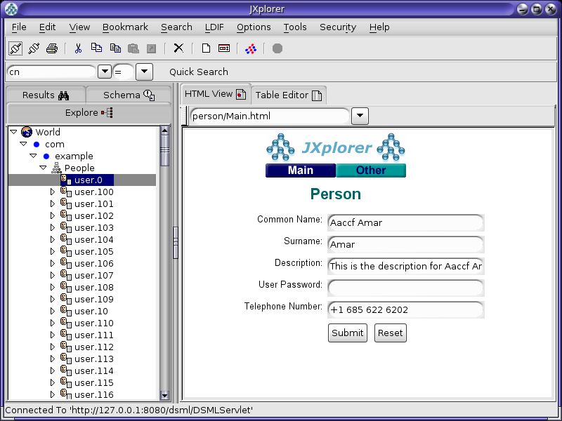
17.6.2.2 Confirming the DSML Gateway Deployment Using the Directory Server Resource Kit
The Directory Server Resource Kit (DSRK) is a collection of utilities that can be used with directory servers. The DSRK was originally intended for use with Oracle Directory Server Enterprise Edition, but in most cases the applications also work with Oracle Unified Directory. The most recent version of the DSRK is included as part of Oracle Directory Server Enterprise Edition 11g Release 1 PS1 (11.1.1.7.0), and contains the dsmlsearch and dsmlmodify tools that can interact with a directory server using DSML rather than LDAP.
Note:
Although an older version of these DSML tools was provided with earlier versions of the Directory Server Resource Kit, the version provided with Oracle Directory Server Enterprise Edition 11g Release 1 PS1 (11.1.1.7.0) is strongly recommended because it is easier to use.You can download Oracle Directory Server Enterprise Edition 11g Release 1 PS1 (11.1.1.7.0) from Oracle Technology Network (OTN) here:
http://www.oracle.com/technetwork/middleware/downloads/oid-11g-161194.html
17.6.2.2.1 Using the dsmlsearch Command
The dsmlsearch command is a DSML-based counterpart to the ldapsearch command. dsmlsearch operates in a similar manner to ldapsearch but there are certain key differences. To see usage information, invoke the command with no arguments, as in the following example:
$ ./dsmlsearch
usage: dsmlsearch -h http://host:port -b basedn [options] filter [attributes...]
where:
-h hostURL URL of the directory server
-b basedn  base dn for search
-D binddn  bind dn
-w passwd  bind password (for simple HTTP authentication)
use "-w - " to prompt for a password
-j pwfile  file where password is stored
-s scope   specify the scope of the search
baseObject - For searching only the base entry
singleLevel - For searching only the children
wholeSubtree - For searching the base entry and all childrens
-a deref   specify how aliases are deferenced
neverDerefAliases - Aliases are never dereferenced
derefFindingBaseObj - Dereferenced when finding the base DN
derefAlways - Dereferenced when finding below the base DN
-l seconds specify the maximum number of seconds to wait for the search
-z number  specify the maximum number of entries to return for the search
-f file    specify the name of the file containing the search filter
The dsmlsearch command differs in usage from ldapsearch:
-
The
-hargument is used to provide a URL to use to access the server. It should include the host and port number, as well as the URI for the gateway servlet (for example,http://127.0.0.1:8080/dsml/DSMLServlet). -
The
-bargument is used to specify the search scope, but notice that the values you provide are different (baseObjectinstead ofbase,singleLevelinstead ofone, andwholeSubtreeinstead ofsub). -
The results are output in DSML format, which is not as user-friendly or human-readable as the LDIF output provided by
ldapsearch.
Following is an example usage of this tool.
Note:
The DSML output does not contain any line breaks, but line breaks were added to this example for readability$ ./dsmlsearch -h http://127.0.0.1:8080/dsml/DSMLServlet \-b "dc=example,dc=com" -s baseObject \"(objectClass=*)" <SOAP-ENV:Envelope xmlns:SOAP-ENV="http://schemas.xmlsoap.org/soap/envelope/"> <SOAP-ENV:Body><dsml:batchResponse xmlns:dsml="urn:oasis:names:tc:DSML:2:0:core"> <dsml:searchResponse><dsml:searchResultEntry dn="dc=example,dc=com"><dsml:attr name="objectClass"><dsml:value>domain</dsml:value><dsml:value>top</dsml:value> </dsml:attr><dsml:attr name="dc"><dsml:value>example</dsml:value></dsml:attr> </dsml:searchResultEntry><dsml:searchResultDone><dsml:resultCode code="0"/> </dsml:searchResultDone></dsml:searchResponse></dsml:batchResponse> </SOAP-ENV:Body></SOAP-ENV:Envelope>
17.6.2.2.2 Using the dsmlmodify Utility
The dsmlmodify utility is a DSML-based counterpart to the ldapmodify command, and it can perform add, delete, modify, and modify DN operations over DSML. To see the usage information for this tool, run it with no arguments, as shown in this example:
$ ./dsmlmodify
usage: dsmlmodify -h http://host:port [options] -f file
where:
-h hostURL URL of the directory server
-D binddn  bind dn
-w passwd  bind password (for simple HTTP authentication)
use "-w - " to prompt for a password
-j pwfile  file where password is stored
-f file    specify the name of the file containing
the modifications
As with the dsmlsearch utility, the -h argument specifies a URL, and the output is returned in DSML form. Unlike ldapmodify, the dsmlmodify tool does not accept the changes through standard input. Changes must be specified in a file, and that file must be in DSML format instead of than LDIF, and the changes cannot contain an outer batchRequest wrapper. The following example shows a typical input file.
<addRequest dn="uid=test.user,dc=example,dc=com">
<attr name="objectClass">
<value>top</value>
<value>person</value>
<value>organizationalPerson</value>
<value>inetOrgPerson</value>
</attr>
<attr name="uid">
<value>test.user</value>
</attr>
<attr name="givenName">
<value>Test</value>
</attr>
<attr name="sn">
<value>User</value>
</attr>
<attr name="cn">
<value>Test User</value>
</attr>
<attr name="userPassword">
<value>password</value>
</attr>
</addRequest>
<modifyRequest dn="uid=test.user,dc=example,dc=com">
<modification name="description" operation="replace">
<value>This is the new description</value>
</modification>
</modifyRequest>
<modDNRequest dn="uid=test.user,dc=example,dc=com" newrdn="cn=Test User"
 deleteoldrdn="false" newSuperior="ou=People,dc=example,dc=com" />
<delRequest dn="cn=Test User,ou=People,dc=example,dc=com" />
The following example shows the output from applying these changes. Line breaks have been added to the output to make it more readable:
$ dsmlmodify -h http://127.0.0.1:8080/dsml/DSMLServlet \  -D "cn=Directory Manager" -j pwd-file -f /tmp/test.dsml
<SOAP-ENV:Envelope xmlns:SOAP-ENV="http://schemas.xmlsoap.org/soap/envelope/">
<SOAP-ENV:Body><dsml:batchResponse xmlns:dsml="urn:oasis:names:tc:DSML:2:0:core">
<dsml:addResponse><dsml:resultCode code="0"/></dsml:addResponse>
<dsml:modifyResponse><dsml:resultCode code="0"/></dsml:modifyResponse>
<dsml:modDNResponse><dsml:resultCode code="0"/></dsml:modDNResponse>
<dsml:delResponse><dsml:resultCode code="0"/><dsml:errorMessage>The number of
entries deleted was 1</dsml:errorMessage></dsml:delResponse></dsml:batchResponse>
</SOAP-ENV:Body></SOAP-ENV:Envelope>

$ dsmlmodify -h http://localhost:8080/dsml/DSMLServlet \  -D "cn=directory manager" -j pwd-file -f /tmp/dsml.ldif
<SOAP-ENV:Envelope xmlns:SOAP-ENV="http://schemas.xmlsoap.org/soap/envelope/">
<SOAP-ENV:Body><batchResponse xmlns="urn:oasis:names:tc:DSML:2:0:core">
<addResponse><resultCode code="0"/></addResponse>
<modifyResponse><resultCode code="0"/></modifyResponse>
<modDNResponse><resultCode code="0"/></modDNResponse>
<delResponse><resultCode code="0"/></delResponse></batchResponse>
</SOAP-ENV:Body></SOAP-ENV:Envelope>
17.7 Managing the ODSM Session Timeout
To ensure that ODSM is more secure, the default session timeout is five minutes. You can change this ODSM session timeout setting to a different value from the WebLogic Server Administration Console, as follows:
-
In a browser window, connect to the WebLogic Administration Console (for example,
http://hostname:7001/console), where hostname is the host on which WebLogic Server is running.Enter your administrator user name and password.
-
On the left panel of the Administration Console, in the Domain Structure section, click Deployments.
Note:
If you are using the WebLogic Administration Console with the domain configuration locking feature enabled, then you must first go to the Change Center, click Lock and Edit, and then go to the Domain Structure section and click Deployments. -
When the Summary of Deployments page is displayed, locate and expand odsm in the Deployments table.
-
Under Modules, click /odsm.
-
When the Settings page is displayed, select the Configuration tab.
-
Change the Session Timeout value to the preferred number of seconds (for example 600 seconds).
-
Click Save.
-
Save your changes to
Plan.xmlby clicking OK.Note:
You must specify the path to thePlan.xmlfile the first time you execute this procedure. Afterward, you can update its path from the Overview tab on the Settings page. -
Return to the Deployments page and select odsm.
-
Enable the checkbox next to the ODSM application row, and then click Update action.
-
Enable Redeploy this application using the following deployment files and provide the
Plan.xmlfile that you saved in step 8. -
Click Finish.
Note:
If you are using the WebLogic Administration Console with the domain configuration locking feature enabled, then you must go to the Change Center and click Activate Changes. -
Login to ODSM, and then login to the Oracle Unified Directory directory server.
-
Allow the Oracle Unified Directory server to run for awhile.
After the specified amount of time, you should observe that the session has timed out. In addition,
-
If you set a longer interval, then a Session Timeout pop-up is automatically displayed when the session times out.
-
If you set the session timeout value to a short interval (such as two minutes), then the Session Timeout pop-up is not automatically displayed when the session times out. However, if you perform an action that requires connecting to the server, then the pop-up is displayed.
-
Note:
For more information about using the WebLogic Administration Console with the domain configuration locking feature, see "Use the Change Center" and "Enable and disable the domain configuration lock" in the Oracle WebLogic Server Online Help.