Configuration of generic
keyboard and input devices
The MICROS Retail OSCAR POS
application allows for the configuration of 3 different generic input devices;
two for connection to the PS2 interface and one for connection to the COM
interface.
·
PS2 keyboard (-> PS2 interface)
· Generic PS2 device (-> PS2 interface)
·
Generic COM device (-> COM interface)
The Generic PS2 device and the Generic COM device allow for special adjustments of the
communications between lock and keyboard and the MICROS Retail OSCAR POS application. Both device
drivers use the same data structure for the device data processing. The
difference is that various interfaces are used and that only values of 0 to 255
are permitted for the key codes for generic COM devices and for generic PS2
devices values from 1 to 65535 are permitted. In generic COM devices all
incoming characters are processed; in generic PS2 devices only characters which
can be translated into an ASCII code are processed (this includes the
interpretation off preset keys such as "^", "`"
"`" and ALT-NUMMER keyboard entries).
PS2 keyboard
The ol
The key configuration is the same as
for other keyboards. Special entry fields exist for keyboard type and special
key delay.
|
Keyboard
type |
Defines
the type of keyboard. |
|
Special
keyboard delay |
The
maximum permitted delay time in milliseconds between two related key
sequences. |
The keyboard type is specified by a
data record which includes the following fields:
|
Keyboard type: |
Defined
number un |
|
Description: |
Name of
keyboard type, e.g. “NCR keyboard”. There are no restrictions for name
assignment, bit the name must be obvious for each keyboard used by this
customer. |
|
Key
rows: |
Number
of key rows on this keyboard. |
|
Key
columns: |
Number
of columns on this keyboard. |
|
Note status: |
If this
option is activated, the preset keys are ignored. In such a case the key codes
must be obvious for each key. If this
option is deactivated, the preset keys are ignored. In such a case the key
codes must be obvious for each key. |
Additional data "PS2 key assignment":
Defines the keyboard. An entry must be
made in the data fields for each key on the keyboard:
|
Key code: |
The key
code sent by the keyboard when this key is depressed should be entered in
this field. If the key codes for an unknown keyboard are required, the debug
level should be set to 2 in program PS2 keyboard so that this can be
ascertained manually. The key code entry is done in decimal format. |
|
Key status: |
The appropriate key status. A valid status value can be a combination of
the following: |
|
0 = Default |
|
|
1 = Shift key active |
|
|
2 = Control key active |
|
|
4 = Alt key active |
|
|
8 = Alt
Gr key active |
|
|
16 = Num key active |
|
|
32 =
Shift key active (caps lock or shift-lock) |
|
|
Row: |
Row no.
in which the key is to be found |
|
Column: |
Column
no. in which the key is to be found |
Additional data "PS2 device data
format":
Specifies the start and end sequences or the length of
the device data which can be interpreted by other keyboards, e.g. generic PS2
devices. Data should be
entered in the fields listed
below:
|
Key code: |
First
key code for the start sequence of device data. |
|
Followed by: |
Second
key code for the start sequence of the device data.. The combination of both
codes defines the start sequence of the device data. Unusual combinations
such as "Strg k", "shift escape" are often sent. |
|
End code |
End key
code – in most cases this is the key code of the entry key (65293). If this
value = 0, the value for the number of key codes which follow the start
sequence must be entered in field Length. |
|
Length |
Number of key codes which follow the start
sequence. If the device data length varies, an end code must be defined. |
Generic PS2 device
The new
"Generic PS2 device" allows for configuration of keyboards on which
individuaol keys send multiple character sequences for the status Depressed or
Released. Peripheral devices such as central lock or waiter lock can also be
configured.
Entries
should be made in the following fields:
|
Device
type |
Describes the type of keyboard |
|
Time-out |
The maximum time-out in milliseconds between two related key
sequences |
|
Central lock |
Defines whether this keyboard has a central lock. If so,
a special routine is run to identify the current lock
position. |
|
Waiter lock |
Defines whether this keyboard has a waiter lock ( |
Generic COM device
This
device is similar to the "Generic PS2 device". Read-only
devices such as. Magnetic card
rea
Entries
are required in the following fields:
|
Device type |
Describes the type of keyboard. |
|
Time-out |
The maximum time-out in milliseconds between to related
key sequences |
|
Central lock |
Defines whether this keyboard has a central lock. If so,
a special routine is run to identify the current lock
position. |
|
Waiter lock |
Defines whether this keyboard has a waiter lock ( |
Configuration for generic PS2 device and generic COM device
For both devices, start and end sentinels or a data
length must be defined. While
multiple generic PS2 devices can be specified for the same port, only one
generic COM device can be specified for each COM port.
Since no other
reading devices can be present on a COM port, it is possible to specify the
device data with less precision. While it is strictly recommended to use a
two-key start sentinel and an end sentinel or length for PS2 devices, it is
also possible to define only one start or end code for COM ports (which in fact
is more a separator) and to use timeout processing for the rest. If no start
code has been defined, all incoming codes (coming within Delay milliseconds)
until reception of the end code or until a timeout is reached will be handled
as one data block. If only one start character has been defined, all data
following that code until the next reception of a start character or until a
timeout occurs will be processed as one block (inclusive the start code). If
two start codes have been specified, the data to be processed contain all data
following, but not including the first code.
The data processing will be done in 6
steps:
· First, it is checked which kind of data it
is.
· Second, type dependent replacements take
place (on the original data). For later post-proceccing and re-interpretaion,
the replacements are temporary for the next two steps only.
· Third, a user data block will be built from
the data block which was created by step 2.
·
Fourth, a device data block will be built from the
data block created by step 2.
· Fifth, special user and device data masks
will be used to build user and device data strings for the events to be
generated by the driver.
· Sixth, special handling will be performed
for LOCK (central lock), WAITERPEN (waiter lock / dallas key) and ASC (keybord)
events. In case of LOCK events, the user data will be saved in a special place
for standard Oscar (central-)lock handling. In case of WAITERPEN events, the
data will be stored for Oscar standard (waiter-)lock handling as well.
Additionally, if user data is not zero, the event name will be changed to
WAITERPENn. For ASC events, the handling is very special: In character mode,
the user data will be sent with an ASC-event. In cooked mode, the device data
built in step 5 must have the form “EventName\2Data” or “EventName”, e.g. “ST”
for the ST key or “Z\2.” for the '.' key.
To perform these steps, the database tables described below will be used.
Table “Generic Device”
This table
specifies start and end sentinels for a specific device. For each generic
device, up to 2 codes (Fields “Key code” and “Followed by”) can be used to
specify a start sentinel and one code (Field “End code”) can specify an end
sentinel. An other possibilities to specify the end of a device data frame:
Specification of a fixed data length (Field “Data length”). The fields “Type”
and “Description” are used to specify that specific device. Details:
|
Type |
Unique key value specifying a specific generic input device. |
|
Description |
Device name, not used by the driver. This is the name you select in the “Device type” field of the device of Generic COM / PS2 device. |
|
Key code |
Start code for generic data. For PS2 devices, this is very often the key code of one of the shift keys (shift, ctrl, alt/alt gr). In these cases, nearly always a second key should be used to specify the key code of the next character which then specifies the real start of peripheral data. In case of a COM port device, in most cases only one start code will be used. Only for COM devices: If no start code needs be used (e.g. because all incoming data must be processed), it is possible to specify Key code outside the valid range (0 -255), e.g. -1 (65535), 256 1000... |
|
Followed by |
If not zero, this defines the second code of a start sentinel. If specified, this will be the first byte in the data buffer to be processed by the device driver. If zero, the first byte in the buffer will be Key code (In case of a PS2 device: only if that key code results in an ASCII code in the input buffer). |
|
Data length |
If not zero, specifies the data length of the input data. For PS2 devices, Data length specifies the number of key codes following the start sentinel. It is possible that this is not the no. of bytes put to the input buffer because combinations of shift, ctrl, alt and / or dead keys can result in up to 5 key strokes for one single ASCII character in the input buffer. |
|
End code |
If data length is zero, End code specifies the terminating code (PS2: key code, COM: byte code). If this generally the last code placed into the input buffer. For COM devices: If the value is outside the valid byte code range (0 – 255), no end code will be used. In this case, timeout processing will be used to terminate a data record, and the start code will be used as separator, additionally. |
Table “Data description”
For each device
type, several data definition records can be specified. For each Oscar event
the device can generate, at least one record must be inserted.
The data base fields are as follows:
|
Type |
Key part, corresponds to a record in the generic device table. |
|
Subtype |
Rest of the key. |
|
Event name |
Name of an Oscar event which will be generated when input buffer processing finds out that input data contain information specific to this event. |
|
User data mask |
Is used for user data processing. If input data contain information for this event type, user data will be extracted from the input buffer into a separate temporary data buffer described by the user data table. Data in that temporary data buffer will be processed by that mask. Most characters of the mask are copied directly to the user data buffer, but special sequences starting with “%” and ending with one of “n”, “s”, “b” or “h” process data in the temporary buffer and store them into user data in place of that sequence. The layout of the sequences is as follows: |
|
|
%% or |
|
|
%[[pos]p][value]{n|s|b|h}, where |
|
%% |
will be replaced by a single % character |
|
pos |
decimal number specifying the offset within the temporary buffer where processing starts. Negative numbers specify an offset from the buffer end. The first byte inside the buffer has offset zero. Default value of pos starts at zero and will be incremented after each formatting sequence to the first unprocessed data following the processed data. |
|
value |
decimal value with a meaning depending on the following character: |
|
“n”: |
value specifies the no. of bytes to be copied to the user data buffer. If value is negative or zero, value specifies how many characters less than the number of characters from the current position to the temporary buffer end must be copied. |
|
“s”: |
value specifies an ASCII code which acts as a separator. All data inside the temporary buffer, starting at the current position, up to but excluding the separator, will be copied to the user data buffer. If no separator is present behind the current position, copying will stop at the temporary buffer's end. |
|
“b”: |
value specifies an ASCII code to be placed inside the user data buffer. This format can be used to insert control characters into user data. |
|
“h”: |
value specifies the length of a substring within the temporary data buffer which is given in hexadecimal characters and must be converted to a decimal number. This format is often used by dallas key devices to represent a dallas key value. In case of a negative value or zero, the size is computed the same way as above for “n”. |
If no user data will be needed, the mask field may be empty.
|
Device data mask |
Is used for device data processing. The format must be given in the same syntax as for user data. Processing is the same as for user data, with only two differences: |
|
1. The temporary buffer will be extracted from the input buffer as described by the device data table. |
|
|
2. An extra character will be added to the beginning of the device data buffer, containing the device id of an abstract device. Normally this is the device id of the (dummy) keyboard device. For central or waiter locks, it is the device id of the corresponding lock device. |
|
|
If no device data will be needed, the mask field may be empty. |
|
|
In case of a WAITERPEN event, user data must contain the key value and device data may be empty (it won't be used within the Oscar event). If the key value is zero, no data will be sent with that event. If the key value is not zero, user data will be sent and the event name will be changed to “WAITERPENn”. |
|
|
In case of an ASC event, user data and device data will be processed as explained above: In Ascii mode, user data will be sent with an “ASC” event. In Cooked mode, device data will be split into event name and user data (separator: STX, 0x02). If no separator was specified within the device data mask, device data will be interpreted as event name and no data will be passed with that event. |
|
|
On change only |
If checked, an event will only be generated if user data differ from the user data sent previously with the same event. This might be useful in cases were several different types of data, e.g. Lock and dallas key data, are part of one single data block and only one of them has changed. |
|
Further record |
If checked, further data description records will be checked even if the current record corresponds to the current input data block. If not checked, further records will be processed only if the current record doesn't identify the current input data block to belong to it. |
Table “Type Identifier”
This table
specifies positions within the current input data block which mark the data as
belonging to the corresponding device type and subtype. If the input buffer
contains the specified value for all specified positions, this input data block
is marked as being a valid data block for this subtype, and processing
(replacements, building temporary data buffers for user and device data,
processing data masks and sending event) will take place for this data block.
If not, the next subtype will be checked.
Data fields are:
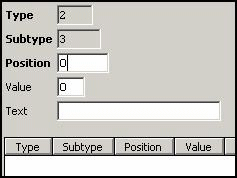
|
Type |
Type, reference to data description. |
|
Subtype |
Subtype, reference to data description. |
|
Position |
Position where string to be compared starts. |
|
Value |
If not zero, ASCII value of the character which must be present at the specified position. |
|
Text |
If Value is zero, specifies a string which must start at the specified position. |
Table “Replacements”
This table
specifies values which must be replaced inside the input buffer by other values
if they are present at a specified position. This replacement will be done
after type check, but before building the temporary buffers for user and device
data. All changes are temporary and only valid for the specified subtype. Data
fields are as follows:
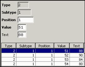
|
Type |
Type, reference to data description. |
|
Subtype |
Subtype, reference to data description. |
|
Position |
Position where the specified value must be present to be replaced. |
|
Value |
ASCII (byte-) value of the character which must be present at that position. |
|
Text |
ASCII (byte-) value of the replacement character. |
Replacements are useful to translate device specific lock positions to
values Oscar needs “P”, “X”, “Z”, “T” or for MSR track numbers (“1”, “2”, “3”).
Generally, is is possible to make substitutions for special characters e.g. in
msr tracks (e.g. exchange “Y” and “Z” on
German keyboards and), but for such chases it is probably better to configure
the correct keyboard layout, e.g. English(US) for most PS2 devices.
Tables “User Data” and “Device Data”
These tables
have the same fields and are processed in the same way. The only difference is
that the user data table specifies how to build the temporary data buffer for
user data while the device data table specifies how to build the temporary data
buffer from the input buffer. Here the data fields and their description:
|
Type |
Type, reference to data description. |
|
Subtype |
Subtype, reference to data description. |
|
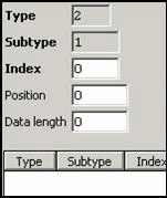
Index |
Increasing number specifying the or |
|
Position |
Position where this part starts. Negative positions specify an offset from the end of the input buffer. |
|
Data length |
Length of this part. Negative length or zero specify how many bytes must remain outside that part at the input buffer end. |
The main reason for these data records is that it must be possible to
combine several parts of the input buffer before they are processed with the
user mask. One (may be the only) example is a dallas key device which sends
data as they are stored within the dallas key. Unfortunately, the first
implementation of a dallas key device in Oscar was based on the TOP line, where
these values where store pair-wise exchanged:
A key value of “123456789ABC” was transmitted as “BC9A78563412” and
converted into an integer value of 207371629900818. If other dallas key devices
should create compatible values, it is necessary to specify 6 parts of each 2
characters, starting from right to left to combine the input data of something
like “...123456789ABC...” into a temporary buffer which should contain
“BC9A78563412” since this can be converted using “%12h” into 207371629900818.
Example 1 (Generic COM Device)
This example is
a device configuration for the so called MICROS Retail Mouse, a combination of a
central lock and a dallas key lock. The device is connected via COM port. The
software interface is similar to TOPcash with very restricted command set (only
status command).
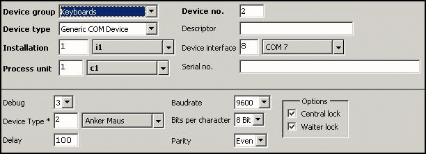
Device:
This record sets
the the device characteristics. Inter-character-delay is very inportant because
this device doesn't use an end code.
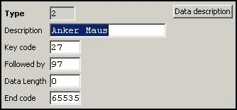
Generic Device:
Here the start
sequence ESC a is defined. Since we have no terminator, data block termination
will be done via timeout processing (Delay parameter in Device) or via ESC as
separator.
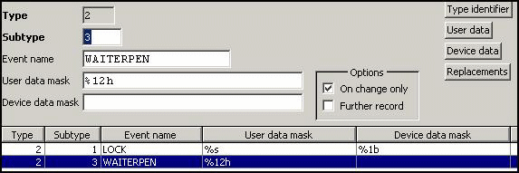
Data Description:
We have two data
description records, one for central lock data (1st byte behind ESC a) and one for dallas key data (starting immediately
behind the key lock status):
LOCK:

WAITERPEN:
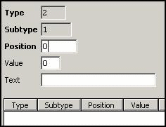
Type Identifier:
No records in
this table for this type / subtype combinations. Result: Since all (zero)
records fit the condition that all specified positions (no positions) must have
the specified values, all records will be selected for the subtype.
LOCK: WAITERPEN:
Replacements:
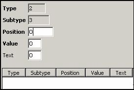
Only for the
central lock, some replacements must be done (“3” → “X”,
“4” → “Z”, “5” → “T” and “6” → “P”, each at
position 1):
LOCK: WAITERPEN:
Device Data:
Neither central
lock nor waiter lock need any device data, so these records are all empty.
LOCK: WAITERPEN:
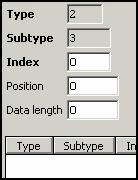
User Data:
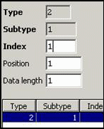
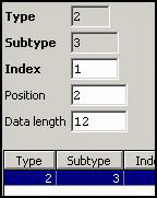
User data are
defined for both, central and waiter lock. For the so called MICROS Retail Mouse, the
dallas key data must rot be reor
Nevertheless,
central lock position is specified at position 1 (starting at zero) and waiter
pen data start at position 2 (12 characters).
LOCK: WAITERPEN:
Example 2 (Generic PS2 Device)
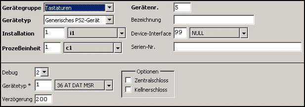
This example is a device configuration for a magnetic card rea
Device:
This record
specifies the specific generic device. The delay isn't so important, but it
should guarantees that card data won't be entered manually.
Generic Device:
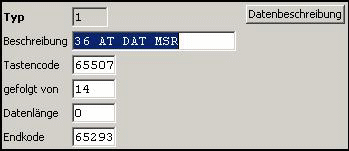
Here start and
end sentinels will be specified. 65507 is the key code for ctrl (left), 14 is
'N' while ctrl is pressed, and 65293 is the key code for the Return key:
Data Description:
Here we have
only one record since the device generates only CARDREADER events.

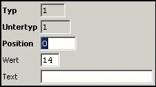
Type Identifier:
Here we have
only one record specifying all data blocks containing ctrl-N, which is always
present since it is part of the start sentinel.
Replacements:
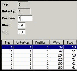
Here we have
several records to replace the track number specifiers. If an English keyboard
layout is used, the track specifiers are “|” and “}” , for a German keyboard
“'” and “*”.
For a German
keyboard, it is necessary to replace “´” by “=” as well (this is the field
separator), All other values will be unchanged. This is enough since track 2
and 3 contain only numerical data. To ensure that replacement for all track
data may take place, for each possible position (2 – 99) a replacement record
has been created. In the screen shot, only the first few such records are
shown, the remaining records differ only in the position field.
Device Data:
Only one byte at
position 1, the (replaced) track no., is part of device data.
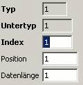
User Data:
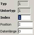
One record which selects all data starting
at position 2 to the end of the record (to 0th byte from the
end of the data block).