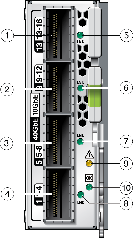
Receptacles
and LEDs

On the front panel there are four link (LNK) LEDs to the right of each port and two
LEDs above and to the right of the bottom LNK LED, that signal the port state. This
figure and this table explains the meaning of the LEDs.
|
|
|
1
|
QSFP port 13 (40 GbE mode)
QSFP port 13-16 (4x10 GbE mode)
|
|
2
|
QSFP port 9 (40 GbE mode)
QSFP port 9-12 (4x10 GbE mode)
|
|
3
|
QSFP port 5 (40 GbE mode)
QSFP port 5-8 (4x10 GbE mode)
|
|
4
|
QSFP port 1 (40 GbE mode)
QSFP port 1-4 (4x10 GbE mode)
|
|
5, 6, 7, 8
|
QSFP link LEDs (Green)
|
|
9
|
Module FAULT LED (Amber)
|
|
10
|
Module OK LED (Green)
|
|
