5 Dimensioning
This chapter describes dimensioning issues and calculations required to maximize the efficiency of the new network, addressing scalability, redundancy schemes, throughput calculations for both normal and failover mode, LAN/WAN considerations, and retransmission concepts.
About bandwidth, throughput, transaction units, and TPS
Bandwidth is the maximum amount of data that can pass through a network at any given time; it is the Advertised Capacity of a card.
Throughput is the amount of data that is actually transmitted in that given time. Throughput reflects an end-to-end rate, which is affected by various conditions during the transmission. Throughput is always lower than bandwidth.
Transactions versus transaction units and TPS
In SS7 signaling, a transaction is typically defined as one MSU transmitted and one MSU received, and assumes a worst-case scenario of that many MSUs both transmitted and received simultaneously per second.
IP signaling capacity is not usually constrained by the IP network (bandwidth), but rather by the processing platform (CPU or memory). The cost of a given transaction varies based upon the feature set triggered by the transaction. Not all MSUs are the same, and not all configurations are the same. Rather than to continue to engineer product capacity for the worst case and thereby penalizing customers who are not using worst-case scenarios, Oracle is providing the Transaction Unit (TU) model to allow customers flexibility in how to use application or card capacity.
Under the TU model, a transaction unit indicates the relative cost of an IP signaling transaction; the base transaction unit is 1.0. Some transactions are more expensive than others in terms of IP signaling card capacity. A transaction that is less expensive than the base has a transaction unit less than 1.0, and a transaction that is more expensive is greater than 1.0. The total transaction units consumed by an MSU are the sum of the base transaction unit value and the additional transaction unit value. Transaction Units per Second (TPS) are then calculated with the total transaction unit value and the Advertised Card capacity.
For detailed information on how to calculate IP signaling TPS and the number of cards required to carry MSU traffic, see How to calculate transaction units per second (TPS) and Calculate the Number of Cards Required.
Scalability
Scalability is the ability to increase total throughput under an increased load proportionally to added resources such as hardware or software. For example, to add traffic and to increase throughput in a current system, the operator can replace low-speed links with IP-based links; IP-based links are much more efficient than standard TDM links. This change requires at least one card that runs the IPGWx, IPLIMx or IPSG application.
Link Equivalency
Table 5-1 shows a single IPLIMx application can take the place of 52 to 80 56K DS0 low-speed links; a single application (M3UA) can take the place of 12 to 80 56K DS0 low-speed links.
Table 5-2 shows Link Equivalency for IPSG on E5-ENET.
Table 5-3 and Table 5-4 show Link Equivalency for IPSG on E5-ENET-B.
Table 5-5 and Table 5-6 show Link Equivalency for IPSG on SLIC.
Table 5-1 EAGLE Link Equivalency for IPLIMx/IPGWx
| ATM <-> Low Speed Link | M2PA <-> ATM <-> Low Speed Link | M3UA <-> ATM <-> Low Speed Link | |||||||||
|---|---|---|---|---|---|---|---|---|---|---|---|
| Avg. MSU Size (MTP 2 + MTP 3) | EAGLE ATM Link Msu/Sec | 56K Links ATM Equivalent | 64K Links ATM Equivalent | EAGLE M2PA Msu/Sec | ATM Link Equivalent | 56K Links IP Equivalent | 64K Links IP Equivalent | EAGLE M3UA Msu/Sec | ATM Links Equivalent | 56K Links IP Equivalent | 64K Links IP Equivalent |
| 20 | 2000 | 6 | 5 | 4000 | 2 | 12 | 10 | 4000 | 2 | 12 | 10 |
| 30 | 2000 | 9 | 8 | 4000 | 2 | 18 | 15 | 4000 | 2 | 18 | 15 |
| 40 | 1800 | 11 | 9 | 4000 | 3 | 23 | 20 | 4000 | 3 | 23 | 20 |
| 50 | 1800 | 13 | 12 | 4000 | 3 | 29 | 25 | 4000 | 3 | 29 | 25 |
| 60 | 1800 | 16 | 14 | 4000 | 3 | 35 | 30 | 4000 | 3 | 35 | 30 |
| 70 | 1800 | 18 | 16 | 4000 | 3 | 40 | 35 | 4000 | 3 | 40 | 35 |
| 80 | 1800 | 21 | 18 | 4000 | 3 | 46 | 40 | 4000 | 3 | 46 | 40 |
| 90 | 1200 | 16 | 14 | 4000 | 4 | 52 | 45 | 4000 | 4 | 52 | 45 |
| 100 | 1200 | 18 | 15 | 4000 | 4 | 58 | 50 | 4000 | 4 | 58 | 50 |
| 110 | 1200 | 19 | 17 | 4000 | 4 | 63 | 55 | 4000 | 4 | 63 | 55 |
| 120 | 1200 | 21 | 18 | 4000 | 4 | 69 | 60 | 4000 | 4 | 69 | 60 |
| 130 | 1200 | 23 | 20 | 4000 | 4 | 75 | 65 | 4000 | 4 | 75 | 65 |
| 140 | 900 | 18 | 16 | 4000 | 5 | 80 | 70 | 4000 | 5 | 80 | 70 |
| 150 | 900 | 20 | 17 | 4000 | 5 | 86 | 75 | 2800 | 4 | 60 | 53 |
| 160 | 900 | 21 | 18 | 4000 | 5 | 92 | 80 | 2800 | 4 | 64 | 56 |
| 170 | 900 | 22 | 20 | 4000 | 5 | 98 | 85 | 2800 | 4 | 68 | 60 |
| 180 | 900 | 24 | 21 | 4000 | 5 | 103 | 90 | 2800 | 4 | 72 | 63 |
| 190 | 720 | 20 | 18 | 4000 | 6 | 109 | 95 | 2800 | 4 | 76 | 67 |
| 200 | 720 | 21 | 18 | 4000 | 6 | 115 | 100 | 2800 | 4 | 80 | 70 |
| 210 | 720 | 22 | 19 | 4000 | 6 | 120 | 105 | 2800 | 4 | 84 | 74 |
| 220 | 720 | 23 | 20 | 4000 | 6 | 126 | 110 | 2800 | 4 | 88 | 77 |
| 230 | 720 | 24 | 21 | 4000 | 6 | 132 | 115 | 2800 | 4 | 92 | 81 |
| 240 | 600 | 21 | 18 | 4000 | 7 | 138 | 120 | 2800 | 5 | 96 | 84 |
| 250 | 600 | 22 | 19 | 4000 | 7 | 143 | 125 | 2800 | 5 | 100 | 88 |
| 260 | 600 | 23 | 20 | 4000 | 7 | 149 | 130 | 2800 | 5 | 104 | 91 |
| 270 | 600 | 24 | 21 | 4000 | 7 | 155 | 135 | 2800 | 5 | 108 | 95 |
Table 5-2 EAGLE Link Equivalency for IPSG on E5-ENET
| ATM <-> Low Speed Link | M2PA <-> ATM <-> Low Speed Link | M3UA <-> ATM <-> Low Speed Link | |||||||||
|---|---|---|---|---|---|---|---|---|---|---|---|
| Avg. MSU Size (MTP 2 + MTP 3) | EAGLE ATM Link Msu/Sec | 56K Links ATM Equivalent | 64K Links ATM Equivalent | EAGLE M2PA Msu/Sec | ATM Link Equivalent | 56K Links IP Equivalent | 64K Links IP Equivalent | EAGLE M3UA Msu/Sec | ATM Links Equivalent | 56K Links IP Equivalent | 64K Links IP Equivalent |
| 20 | 2000 | 6 | 5 | 5000 | 3 | 15 | 13 | 5000 | 3 | 15 | 13 |
| 30 | 2000 | 9 | 8 | 5000 | 3 | 22 | 19 | 5000 | 3 | 22 | 19 |
| 40 | 1800 | 11 | 9 | 5000 | 3 | 29 | 25 | 5000 | 3 | 29 | 25 |
| 50 | 1800 | 13 | 12 | 5000 | 3 | 36 | 32 | 5000 | 3 | 36 | 32 |
| 60 | 1800 | 16 | 14 | 5000 | 3 | 43 | 38 | 5000 | 3 | 43 | 38 |
| 70 | 1800 | 18 | 16 | 5000 | 3 | 50 | 44 | 5000 | 3 | 50 | 44 |
| 80 | 1800 | 21 | 18 | 5000 | 3 | 58 | 50 | 5000 | 3 | 58 | 50 |
| 90 | 1200 | 16 | 14 | 5000 | 5 | 65 | 57 | 5000 | 5 | 65 | 57 |
| 100 | 1200 | 18 | 15 | 5000 | 5 | 72 | 63 | 5000 | 5 | 72 | 63 |
| 110 | 1200 | 19 | 17 | 5000 | 5 | 79 | 69 | 5000 | 5 | 79 | 69 |
| 120 | 1200 | 21 | 18 | 5000 | 5 | 86 | 75 | 5000 | 5 | 86 | 75 |
| 130 | 1200 | 23 | 20 | 5000 | 5 | 93 | 82 | 5000 | 5 | 93 | 82 |
| 140 | 900 | 18 | 16 | 5000 | 6 | 100 | 88 | 5000 | 6 | 100 | 88 |
| 150 | 900 | 20 | 17 | 5000 | 6 | 108 | 94 | 5000 | 6 | 108 | 94 |
| 160 | 900 | 21 | 18 | 5000 | 6 | 115 | 100 | 5000 | 6 | 115 | 100 |
| 170 | 900 | 22 | 20 | 5000 | 6 | 122 | 107 | 5000 | 6 | 122 | 107 |
| 180 | 900 | 24 | 21 | 5000 | 6 | 129 | 113 | 5000 | 6 | 129 | 113 |
| 190 | 720 | 20 | 18 | 5000 | 7 | 136 | 119 | 5000 | 7 | 136 | 119 |
| 200 | 720 | 21 | 18 | 5000 | 7 | 143 | 125 | 5000 | 7 | 143 | 125 |
| 210 | 720 | 22 | 19 | 5000 | 7 | 150 | 132 | 5000 | 7 | 150 | 132 |
| 220 | 720 | 23 | 20 | 5000 | 7 | 158 | 138 | 5000 | 7 | 158 | 138 |
| 230 | 720 | 24 | 21 | 5000 | 7 | 165 | 144 | 5000 | 7 | 165 | 144 |
| 240 | 600 | 21 | 18 | 5000 | 9 | 172 | 150 | 5000 | 9 | 172 | 150 |
| 250 | 600 | 22 | 19 | 5000 | 9 | 179 | 157 | 5000 | 9 | 179 | 157 |
| 260 | 600 | 23 | 20 | 5000 | 9 | 186 | 163 | 5000 | 9 | 186 | 163 |
| 270 | 600 | 24 | 21 | 5000 | 9 | 193 | 169 | 5000 | 9 | 193 | 169 |
Table 5-3 EAGLE Link Equivalency for IPSG on E5-ENET-B (E5-ENET-B when IPSG High Throughput Feature OFF, E5-ENET)
| ATM <-> Low Speed Link | M2PA <-> ATM <-> Low Speed Link | M3UA <-> ATM <-> Low Speed Link | |||||||||
|---|---|---|---|---|---|---|---|---|---|---|---|
| Avg. MSU Size (MTP 2 + MTP 3) | EAGLE ATM Link Msu/Sec | 56K Links ATM Equivalent | 64K Links ATM Equivalent | EAGLE M2PA Msu/Sec | ATM Link Equivalent | 56K Links IP Equivalent | 64K Links IP Equivalent | EAGLE M3UA Msu/Sec | ATM Links Equivalent | 56K Links IP Equivalent | 64K Links IP Equivalent |
| 20 | 2000 | 6 | 5 | 6500 | 3 | 19 | 16 | 6500 | 3 | 19 | 16 |
| 30 | 2000 | 9 | 8 | 6500 | 3 | 28 | 24 | 6500 | 3 | 28 | 24 |
| 40 | 1800 | 11 | 9 | 6500 | 4 | 37 | 33 | 6500 | 4 | 37 | 33 |
| 50 | 1800 | 13 | 12 | 6500 | 4 | 46 | 41 | 6500 | 4 | 46 | 41 |
| 60 | 1800 | 16 | 14 | 6500 | 4 | 56 | 49 | 6500 | 4 | 56 | 49 |
| 70 | 1800 | 18 | 16 | 6500 | 4 | 65 | 57 | 6500 | 4 | 65 | 57 |
| 80 | 1800 | 21 | 18 | 6500 | 4 | 74 | 65 | 6500 | 4 | 74 | 65 |
| 90 | 1200 | 16 | 14 | 6500 | 5 | 83 | 73 | 6500 | 5 | 83 | 73 |
| 100 | 1200 | 18 | 15 | 6500 | 5 | 92 | 81 | 6500 | 5 | 92 | 81 |
| 110 | 1200 | 19 | 17 | 6500 | 5 | 102 | 89 | 6500 | 5 | 102 | 89 |
| 120 | 1200 | 21 | 18 | 6500 | 5 | 112 | 97 | 6500 | 5 | 112 | 97 |
| 130 | 1200 | 23 | 20 | 6500 | 5 | 120 | 105 | 6500 | 5 | 120 | 105 |
| 140 | 900 | 18 | 16 | 6500 | 7 | 130 | 114 | 6500 | 7 | 130 | 114 |
| 150 | 900 | 20 | 17 | 6500 | 7 | 138 | 122 | 6500 | 7 | 138 | 122 |
| 160 | 900 | 21 | 18 | 6500 | 7 | 148 | 130 | 6500 | 7 | 148 | 130 |
| 170 | 900 | 22 | 20 | 6500 | 7 | 159 | 138 | 6500 | 7 | 159 | 139 |
| 180 | 900 | 24 | 21 | 6500 | 7 | 167 | 148 | 6500 | 7 | 167 | 148 |
| 190 | 720 | 20 | 18 | 6500 | 9 | 176 | 155 | 6500 | 9 | 176 | 155 |
| 200 | 720 | 21 | 18 | 6500 | 9 | 186 | 163 | 6500 | 9 | 186 | 163 |
| 210 | 720 | 22 | 19 | 6500 | 9 | 197 | 171 | 6500 | 9 | 197 | 171 |
| 220 | 720 | 23 | 20 | 6500 | 9 | 203 | 181 | 6500 | 9 | 203 | 181 |
| 230 | 720 | 24 | 21 | 6500 | 9 | 217 | 186 | 6500 | 9 | 217 | 186 |
| 240 | 600 | 21 | 18 | 6500 | 11 | 224 | 197 | 6500 | 11 | 224 | 197 |
| 250 | 600 | 22 | 19 | 6500 | 11 | 232 | 203 | 6500 | 11 | 232 | 203 |
| 260 | 600 | 23 | 20 | 6500 | 11 | 241 | 210 | 6500 | 11 | 241 | 210 |
| 270 | 600 | 24 | 21 | 6500 | 11 | 250 | 217 | 6500 | 11 | 250 | 217 |
Table 5-4 EAGLE Link Equivalency for IPSG on E5-ENET-B (E5-ENET-B IPSG High Throughput Feature ON)
| ATM <-> Low Speed Link | M2PA <-> ATM <-> Low Speed Link | M3UA <-> ATM <-> Low Speed Link | |||||||||
|---|---|---|---|---|---|---|---|---|---|---|---|
| Avg. MSU Size (MTP 2 + MTP 3) | EAGLE ATM Link Msu/Sec | 56K Links ATM Equivalent | 64K Links ATM Equivalent | EAGLE M2PA Msu/Sec | ATM Link Equivalent | 56K Links IP Equivalent | 64K Links IP Equivalent | EAGLE M3UA Msu/Sec | ATM Links Equivalent | 56K Links IP Equivalent | 64K Links IP Equivalent |
| 20 | 2000 | 6 | 5 | 9500 | 5 | 27 | 24 | 9048 | 4 | 25 | 22 |
| 30 | 2000 | 9 | 8 | 9500 | 5 | 41 | 36 | 9048 | 4 | 38 | 33 |
| 40 | 1800 | 11 | 9 | 9500 | 5 | 54 | 48 | 9048 | 4 | 50 | 44 |
| 50 | 1800 | 13 | 12 | 9500 | 5 | 68 | 59 | 9048 | 4 | 63 | 55 |
| 60 | 1800 | 16 | 14 | 9500 | 5 | 81 | 71 | 9048 | 4 | 76 | 66 |
| 70 | 1800 | 18 | 16 | 9500 | 5 | 95 | 83 | 9048 | 4 | 88 | 77 |
| 80 | 1800 | 21 | 18 | 9500 | 5 | 108 | 95 | 9048 | 4 | 101 | 88 |
| 90 | 1200 | 16 | 14 | 9500 | 8 | 122 | 107 | 9048 | 7 | 114 | 99 |
| 100 | 1200 | 18 | 15 | 9500 | 8 | 136 | 118 | 9048 | 7 | 126 | 110 |
| 110 | 1200 | 19 | 17 | 9500 | 8 | 148 | 132 | 9048 | 7 | 139 | 121 |
| 120 | 1200 | 21 | 18 | 9500 | 8 | 164 | 142 | 9048 | 7 | 151 | 132 |
| 130 | 1200 | 23 | 20 | 9387 | 8 | 176 | 153 | 8870 | 7 | 161 | 141 |
| 140 | 900 | 18 | 16 | 9277 | 11 | 190 | 167 | 8700 | 10 | 170 | 149 |
| 150 | 900 | 20 | 17 | 9170 | 11 | 202 | 179 | 8535 | 9 | 179 | 156 |
| 160 | 900 | 21 | 18 | 9065 | 11 | 216 | 190 | 8377 | 9 | 187 | 164 |
| 170 | 900 | 22 | 20 | 8962 | 11 | 232 | 202 | 8225 | 9 | 195 | 171 |
| 180 | 900 | 24 | 21 | 8862 | 11 | 244 | 216 | 8078 | 9 | 203 | 177 |
| 190 | 720 | 20 | 18 | 8764 | 13 | 257 | 226 | 7936 | 11 | 210 | 184 |
| 200 | 720 | 21 | 18 | 8668 | 13 | 271 | 238 | 7800 | 11 | 218 | 190 |
| 210 | 720 | 22 | 19 | 8574 | 13 | 288 | 250 | 7668 | 11 | 225 | 196 |
| 220 | 720 | 23 | 20 | 8482 | 13 | 297 | 264 | 7540 | 10 | 231 | 202 |
| 230 | 720 | 24 | 21 | 8392 | 13 | 317 | 271 | 7416 | 10 | 238 | 208 |
| 240 | 600 | 21 | 18 | 8304 | 16 | 328 | 288 | 7296 | 12 | 244 | 214 |
| 250 | 600 | 22 | 19 | 8218 | 16 | 339 | 297 | 7180 | 12 | 250 | 219 |
| 260 | 600 | 23 | 20 | 8134 | 16 | 352 | 306 | 7068 | 12 | 256 | 224 |
| 270 | 600 | 24 | 21 | 8051 | 16 | 365 | 317 | 6960 | 12 | 262 | 229 |
Table 5-5 EAGLE Link Equivalency for IPSG on SLIC for EAGLE 46.5
| Avg. MSU Size (MTP2 + MTP3) | EAGLE ATM Link MSU/Sec | EAGLE M2PA/M3UA MSU/Sec | ATM Link Equivalent | 56K Link Equivalent | 64K Link Equivalent |
|---|---|---|---|---|---|
| 20 | 2000 | 10000 | 5 | 29 | 25 |
| 30 | 2000 | 10000 | 5 | 43 | 38 |
| 40 | 1800 | 10000 | 6 | 58 | 50 |
| 50 | 1800 | 10000 | 6 | 72 | 63 |
| 60 | 1800 | 10000 | 6 | 86 | 75 |
| 70 | 1800 | 10000 | 6 | 100 | 88 |
| 80 | 1800 | 10000 | 6 | 115 | 100 |
| 90 | 1200 | 10000 | 9 | 129 | 113 |
| 100 | 1200 | 10000 | 9 | 143 | 125 |
| 110 | 1200 | 10000 | 9 | 158 | 138 |
| 120 | 1200 | 10000 | 9 | 172 | 150 |
| 130 | 1200 | 10000 | 9 | 186 | 163 |
| 140 | 900 | 10000 | 12 | 200 | 175 |
| 150 | 900 | 10000 | 12 | 215 | 188 |
| 160 | 900 | 10000 | 12 | 229 | 200 |
| 170 | 900 | 10000 | 12 | 243 | 213 |
| 180 | 900 | 10000 | 12 | 258 | 225 |
| 190 | 720 | 10000 | 14 | 272 | 238 |
| 200 | 720 | 10000 | 14 | 286 | 250 |
| 210 | 720 | 10000 | 14 | 300 | 263 |
| 220 | 720 | 10000 | 14 | 315 | 275 |
| 230 | 720 | 10000 | 14 | 329 | 288 |
| 240 | 600 | 10000 | 17 | 343 | 300 |
| 250 | 600 | 10000 | 17 | 358 | 313 |
| 260 | 600 | 10000 | 17 | 372 | 325 |
| 270 | 600 | 10000 | 17 | 386 | 338 |
Table 5-6 EAGLE Link Equivalency for IPSG on SLIC for EAGLE 46.6 and Later Releases
| Avg. MSU Size (MTP2 + MTP3) | EAGLE ATM Link MSU/Sec | EAGLE M2PA/M3UA MSU/Sec | ATM Link Equivalent | 56K Link Equivalent | 64K Link Equivalent |
|---|---|---|---|---|---|
| 20 | 2000 | 12000 | 6 | 35 | 30 |
| 30 | 2000 | 12000 | 6 | 52 | 45 |
| 40 | 1800 | 12000 | 7 | 69 | 60 |
| 50 | 1800 | 12000 | 7 | 86 | 75 |
| 60 | 1800 | 12000 | 7 | 103 | 90 |
| 70 | 1800 | 12000 | 7 | 120 | 105 |
| 80 | 1800 | 12000 | 7 | 138 | 120 |
| 90 | 1200 | 12000 | 10 | 155 | 135 |
| 100 | 1200 | 12000 | 10 | 172 | 150 |
| 110 | 1200 | 12000 | 10 | 189 | 165 |
| 120 | 1200 | 12000 | 10 | 206 | 180 |
| 130 | 1200 | 12000 | 10 | 223 | 195 |
| 140 | 900 | 12000 | 14 | 240 | 210 |
| 150 | 900 | 12000 | 14 | 258 | 225 |
| 160 | 900 | 12000 | 14 | 275 | 240 |
| 170 | 900 | 12000 | 14 | 292 | 255 |
| 180 | 900 | 12000 | 14 | 309 | 270 |
| 190 | 720 | 12000 | 17 | 326 | 285 |
| 200 | 720 | 12000 | 17 | 343 | 300 |
| 210 | 720 | 12000 | 17 | 360 | 315 |
| 220 | 720 | 12000 | 17 | 378 | 330 |
| 230 | 720 | 12000 | 17 | 395 | 345 |
| 240 | 600 | 12000 | 20 | 412 | 360 |
| 250 | 600 | 12000 | 20 | 429 | 375 |
| 260 | 600 | 12000 | 20 | 446 | 390 |
| 270 | 600 | 12000 | 20 | 463 | 405 |
Hardware and software requirements
For SS7-over-IP networks, Oracle Communications uses E5-ENET and E5-ENET-B cards to achieve IP connectivity, usign the IPLIMx, IPGWx, and IPSG applications.
The IPLIMx application implements the M2PA protocol, which is used mainly for B-, C-, and D-links. Once either of the cards is loaded with the IPLIMx application, the card is referred to as the IPLIMx card.
The IPGWx application implements the M3UA and SUA protocols, which are used for A-links. Once either of the cards is loaded with the IPGWx application, the card is referred to as the IPGWx card.
The IPSG application implements the M2PA and M3UA protocols, which are used for A-links (IPSG-M3UA) and B-, C-, and D-links (IPSG-M2PA) signaling links. Once the card is loaded with the IPSG application, it is referred to as an IPSG card.
The number of MSU/s supported by each card is dependent on various factors including MSU size, percentage of MSUs triggering the SCCP Class 1 sequencing feature, and the Integrated Monitoring feature.
System capacity
Note:
Other features, such as Integrated Monitoring, will also require system capacity and must be considered when calculating the available system capacity.The EAGLE is engineered to support a system total capacity as defined in this section where:
- Each E5-ENET or E5-ENET-B card running the IPLIMx or IPGWx application has a maxiumum capacity of 4000 TPS.
- Each E5-ENET card running the IPSG application has a maximum capacity of 5000 TPS.
- Each E5-ENET-B card running the IPSG application when the E5-ENET-B IPSG High Throughput feature is OFF has a maximum capacity of 6500 TPS.
- Each E5-ENET-B card running the IPSG application when the E5-ENET-B IPSG High Throughput feature is ON has a maximum capacity of 9500 TPS.
- Each SLIC card running the IPSG application has a maximum capacity of 12000 TPS.
This capacity is applicable for both of the
following scenarios:
- When the IPSG High Throughput feature is OFF
- When the IPSG High Throughput feature is ON
The system total depends on the system TPS. The total maximum allowed system TPS is 750,000 when the HIPR2 High Rate Mode feature is turned on and 500,000 TPS if the HIPR2 HIgh Rate Mode feature is turned off.
When considering other factors or additional configurations that impact the IMT, contact your Sales Representative for more information.
Achieving IP Signaling Applications’ Advertised Capacity
A goal of properly engineered networks is to eliminate congestion. Advertised Capacity refers to the maximum TPS that can be sustained without congestion. Several factors affect TPS calculations and must be considered when calculating the expected throughput for the IPLIMx, IPGWx and IPSG applications.
The IPGWx application implements traffic flow control based upon the TPS value allocated to its signaling link, which is derived from the iptps parameter setting of its linkset. Presenting a load in excess of the signaling link TPS value will result in congestion.
Factors Affecting Advertised Capacity
The following factors affect the IP application’s Advertised Capacity:
- Host card
Performance Characteristics of the host card can impact the capacity.
- CPU utilization
Various factors determine the processing resources required by IP applications to manage a given traffic load, and cause the processing of each MSU to be more expensive. For example, the EAGLE provides a feature that enables support of Class-1 Global Title traffic. When the feature is enabled and a triggering message is received by an IP signaling application, the application sends the MSU to an SCCP card for translation, and after translation, the MSU is sent back to the originating IP signaling card for post-translation routing. This extra IMT hop results in significant processing overhead in the receiving IP signaling card.
- Message buffers
The amount of memory allocated for traffic buffers determines the maximum traffic rate and average message size that can be sustained for a certain network configuration. The buffer size is configurable through associations. For example, within the constraints of memory on the card, each association can have from 8 kb up to 400 kb of send-and-receive buffer space for SCTP.
- Card communication interfaces
The capacity of the card's external interfaces can become a constraint for certain configurations. For example, the IMT interface capacity is affected by high-utilizing features, or the Ethernet interface configurable capacity is set to half-duplex (not 100Mb/sec full-duplex).
- E5-ENET-B IPSG High Throughput feature
Turning on the E5-ENET-B IPSG High Throughput feature impacts the baseline configuration for the E5-ENET-B IPSG card as shown in Table 5-7
Table 5-7 Baseline Configuration Changes for the E5-ENET-B IPSG High Throughput Feature
E5-ENET-B Card Baseline Configuration E5-ENET-B when IPSG High Throughput Feature OFF, E5-ENET E5-ENET-B IPSG High Throughput feature ON Maximum TPS for the card 6500 9500 Average MSU size (bytes) 0-272 0-120 Max RTT (MS) 120 50 Max number of links/associations 16 4 Protocol M2PA and M3UA M2PA - Card de-rating
If the E5-ENET-B IPSG High Throughput feature is turned on, the traffic rate is greater than 6500 TPS, and the E5-ENET-B IPSG card exceeds the limits shown in Table 5-7, then the card is de-rated according to the following calculations:
- SLK TU cost factor = 1+ (RoundDown (((Number of links - 1)/4) * 0.025)
- MSU size TU cost factor for M2PA links = 1+ (RoundUp(((Average MSU size - 120)/10) * 0.012)
- MSU size TU cost factor for M3UA links = 1+ (RoundUp(((Average MSU size - 120)/10) * 0.02)
- Association RTT cost factor (if greater than 50) = 1+ (RoundDown((Association RTT/25) * 0.04)
- Protocol TU cost factor for M3UA links = 1.05
Note:
When calculating the values for the Average MSU SIF size >120, Number of Links >4, and Association RTT > 50, the values from the division in the formula are rounded to the quotient. In addition, the final values for the Transaction Unit Adjustment and Transaction Unit Cost values for Average MSU SIF size are rounded to the nearest 10 value if the delta is not a multiple of 10.Given the derating factors, a derived SLK IP TPS for an MSU would be calculated as follows:
Derived SLK IP TPS for an MSU = 1 TU (Actual SLK IP TPS) +
(RoundDown (((Number of links - 1)/4) * 0.025) (for number of links > 4) +
(RoundUp(((Average MSU size - 120)/10) * 0.012) (for M2PA) OR
+ (RoundUp(((Average MSU size - 120)/10) * 0.02) (for M3UA)
+ (RoundDown((Association RTT/25) * 0.04) (for RTT>50 ms) +
0.05 (for M3UA)
For detailed descriptions of factors that affect advertised card capacity, see Engineering Rules for Determining IP7 Application Throughput.
Base transaction unit
The base IP signaling transaction unit involves an MSU sent and an MSU received. If the E5-ENET-B, E5-ENET when IPSG High Throughput Feature is turned OFF, then each MSU has a Service Information Field (SIF) of less than or equal to 160 bytes. If the E5-ENET-B IPSG High Throughput feature is turned on, then each MSU has a SIF of less than or equal to 120 bytes.
The base Advertised Capacity of EAGLE IP signaling cards assumes an average transaction unit cost of 1.0, so a TPS rating of 2,000 = 2,000 Transaction Units per Second (TPS), each having a cost of 1.0. If the average transaction cost increases above 1.0, then the Advertised Capacity (TPS rating) of the IP signaling card decreases proportionally.
Table 5-8 shows the base Advertised Capacity for IPSG application on applicable cards.
Table 5-8 Base Advertised Capacity for IPSG Cards
| Card | Base Advertised Capacity (TPS) |
|---|---|
| E5-ENET | 5,000 for IPSG
4000 for IPGWx/IPLIMx |
| E5-ENET-B (E5-ENET-B when IPSG High Throughput Feature OFF, E5-ENET or SLIC) | 6500 for IPSG
4000 for IPGWx/IPLIMx |
| E5-ENET-B (E5-ENET-B IPSG High Throughput ON) | 9500 for IPSG
4000 for IPGWx/IPLIMx |
| SLIC | 12000 for IPSG |
Exceeding the Advertised Capacity may result in signaling congestion, and in combination with the E5IS Data Feed feature, may result in the application discarding E5IS Data Feed messages.
Base Transaction Unit Rules: IPLIMx, IPGWx, and IPSG (E5-ENET-B when IPSG High Throughput Feature OFF, E5-ENET)
The base transaction unit rules are applied to establish the base transaction unit costs:
- Sufficient IP TPS is assigned to the linkset to which the IPGWx signaling link is assigned. (IPGWx only) or sufficient IP TPS (both Reserved and Max SLKPTS is assigned to each link of an IPSG linkset.
- The traffic is not monitored via the E5IS or Fast Copy features.
- For IPGWx and IPLIMx, the percentage of received traffic that triggers the enabled EAGLE SCCP Class-1 Sequencing feature is less than or equal to 50%.
- For IPSG, none of the received traffic triggers the enabled Eagle SCCP Class-1 Sequencing feature.
- The IP packet-loss rate is 25 per 100,000 or less.
- The IP connection message buffer memory is of a sufficient size on the local SCTP association and peer network elements to sustain traffic for the network's RTT and worst-case packet loss.
- The IP connection retransmission mode must be linear (RMODE=LIN) for SCTP associations.
- The IP connection retransmit time-out is configured to a value that is appropriate for the expected network latency (RMIN for SCTP associations).
- Number of open IP connections is less than or equal to 8 (IPGW links) or 16 (IPSG links).
- Number of active SLKs is less than or equal to half the maximum supported on the IPLIMx card (<=8 for E5-ENET or E5-ENET-B).
- M2PA Timer T7 (Excess Delay in ACK) is configured to have a value appropriate for the expected network latency (IPLIMx and IPSG M2PA links).
- The IP connection minimum congestion window (CWMIN) is configured to an appropriate value to achieve the target IP TPS on the link.
- The peer network element acknowledgment timer (SACK timer) is set to an appropriate value in correlation with the local IP connection RMIN and the expected network latency.
Base Transaction Unit Rules (E5-ENET-B IPSG High Throughput ON)
In addition to the rules specified in Base Transaction Unit Rules: IPLIMx, IPGWx, and IPSG (E5-ENET-B when IPSG High Throughput Feature OFF, E5-ENET), the following base transaction rules apply to E5-ENET-B IPSG cards when the E5-ENET-B IPSG High Throughput feature is turned on:
- Number of links provisioned is less than or equal to 4
- The average MSU size per second carried by IPSG links is less than or equal to 120 bytes.
- The network round trip time (RTT) is less than or equal to 50 ms.
- The traffic is carried by M2PA links.
For IPSG configuration exceeding these rules, additional TU adjustment costs as shown in Table 5-14 are enforced for deriving TUs consumed by a signaling link (SLK). If the derived TU cost exceeds the configured SLKTPS/MAXSLKTPS on an IPSG SLK, it will result in congestion of the link and discard of the MSUs.
Base Transaction Unit Rules for SLIC IPSG
In addition to the rules specified in Base Transaction Unit Rules: IPLIMx, IPGWx, and IPSG (E5-ENET-B when IPSG High Throughput Feature OFF, E5-ENET), the following rules apply:
- E5-ENET-B capacity feature setting does not affect IPSG on SLIC below 10K TU.
- GTT enabled on SLIC IPSG feature may generate additional traffic for GTT actions, for example, the DUPLICATE GTT action). When a GTT-enabled IPSG on SLIC card generates additional MSUs because of the configuration, an additional TU cost of one is added for each MSU duplicated or additional MSU generated because of the duplication.
For configuration deviating from the above rules, an additional TU cost need to be added to the base TU cost as described in the below table in order to derive total TU capacity consumed by the IPSG SLK. The additional TU cost is not enforced by the IPSG application, but any deviation from the above baseline will degrade the IPSG application performance eventually resulting in load shedding on IPSG application.
Table 5-9 IPSG Additional Transaction Units for Advanced Configurations
| Configuration Attribute | Average MSU SIF size | Transaction Unit Adjustment(per MSU with Attribute) | Transaction Unit Cost(per MSU with Attribute) |
|---|---|---|---|
| MSU Size |
0..160 |
0 | 1.0 |
|
161..272 |
0.15 | 1.15 | |
| More than 16 Open IP Connections on IPSG card | 0..272 | 0.135 * INT (# of connections / 16) | 1 + (135 * INT(# of connections / 16) |
| MSU Triggers enabled SCCP Class-1 Sequencing feature | 0..272 |
0.2 |
1.2 |
| MSU Triggers SLAN copy | 0..272 | 0.00143 * MSU Size |
1 + (00143 * MSU size) |
| MTP-Routed SCCP Conversion feature enabled | 0..272 | 0.00143 * MSU Size |
1 + (00143 * MSU size) |
| MSU is copied by STC Data Feed | 0..272 | 0.43 | 1.43 |
| MSU is copied by Fast Copy | 0..140 | 0.00 | 1.00 |
| 141.272 | 0.32 | 1.32 | |
| GTT enabled on IPSG | 0..160 | 0.00 | 1.00 |
| 161..272 | 0.15 | 1.15 |
Base Transaction Unit Costs: IPLIMx, IPGWx
The base transaction unit cost is based on the configuration rules shown in Base Transaction Unit Rules: IPLIMx, IPGWx, and IPSG (E5-ENET-B when IPSG High Throughput Feature OFF, E5-ENET). Any additional configurations are applied to the adjusted transaction unit.
Table 5-10 Base Transaction Unit Cost Per MSU SIF Size
| MSU SIF | M2PA | M3UA | SUA |
|---|---|---|---|
| 0..140 | 1 | 1 | 1.33 |
| 141..272 | 1 | 1.4 | 2 |
| 273..544 | 2 | 2 | N/A |
| 545..816 | 3 | 3 | N/A |
| 817..1088 | 4 | 4 | N/A |
| 1089..1360 | 5 | 5 | N/A |
| 1361..1632 | 6 | 6 | N/A |
| 1633..1904 | 7 | 7 | N/A |
| 1905..2176 | 8 | 8 | N/A |
| 2177..2448 | 9 | 9 | N/A |
| 2449..2720 | 10 | 10 | N/A |
| 2721..2992 | 11 | 11 | N/A |
| 2993..3264 | 12 | 12 | N/A |
| 3265..3536 | 13 | 13 | N/A |
| 3537..3808 | 14 | 14 | N/A |
| 3809..4080 | 15 | 15 | N/A |
| 4081..4095 | 16 | 16 | N/A |
Base Transaction Unit Costs: IPSG
Note:
When calculating the values for the Average MSU SIF size >120, the values from the division in the formula are rounded to the quotient. In addition, the final values for the Transaction Unit Adjustment and Transaction Unit Cost values for Average MSU SIF size are rounded to the nearest 10 value if the delta is not a multiple of 10.Table 5-11 Base Transaction Unit Cost Per MSU SIF Size for IPSG Cards
| MSU SIF or UA Data Parm Size | E5-ENET IPSG Transaction Unit Cost | E5-ENET-B IPSG Transaction Unit Cost* | E5-ENET-B IPSG High Throughput Feature |
|---|---|---|---|
| 0-160 | 1 | 1 | OFF |
| 161-272 | 1.15 | 1.15 | OFF |
| 0-120 | 1 | 1 | ON |
| 121-272 | Defaults to the TU costs used for the E5-ENET-B card when the E5-ENET-B IPSG High Throughput feature is OFF. |
M2PA: 1+ (RoundUp((Average MSU size – 120)/10)) * 0.012) M3UA: 1 + (RoundUp((Average MSU size – 120)/10)) * 0.02) |
ON |
| 273..544 | 2 | 2 | N/A |
| 545..816 | 3 | 3 | N/A |
| 817..1088 | 4 | 4 | N/A |
| 1089..1360 | 5 | 5 | N/A |
| 1361..1632 | 6 | 6 | N/A |
| 1633..1904 | 7 | 7 | N/A |
| 1905..2176 | 8 | 8 | N/A |
| 2177..2448 | 9 | 9 | N/A |
| 2449..2720 | 10 | 10 | N/A |
| 2721..2992 | 11 | 11 | N/A |
| 2993..3264 | 12 | 12 | N/A |
| 3265..3536 | 13 | 13 | N/A |
| 3537..3808 | 14 | 14 | N/A |
| 3809..4080 | 15 | 15 | N/A |
| 4081..4095 | 16 | 16 | N/A |
Note:
*Values in the "E5-ENET-B IPSG Transaction Unit Cost" column aply to IPSG cards where type=enetb and the card is routing more than 6500 MSU/s. Other IPSG scenarios use the "E5-ENET IPSG Transaction Unit Cost" column values.Adjusted transaction unit
The adjusted transaction unit is the value calculated and tested by Oracle that represents additional cost per base transaction unit when the configuration deviates from the base configuration.
Note:
When computing TU cost for configuration attributes such as size and number of connections/links on IPSG cards the TU used will be from Table 5-13 or Table 5-14, depending on whether an E5-ENET or E5-ENET-B card is used and the status of the E5-ENET-B IPSG High Throughput feature.Table 5-12 Additional IPLIMx/IPGWx Transaction Units for Advanced Configurations
| MSU SIF Size | Adapter | Moni- tored E5IS Data Feed | Number of Open ConnsFoot 1 | SLAN and/or SCCP Conver- sion | Base TU | TU Adjust- ment | Total TU | Max MSU/s 2000 | Max MSU/s 4000 |
|---|---|---|---|---|---|---|---|---|---|
| 0..140 | M3UA | Yes | <= 8 | No | 1.0 | 0.43 | 1.43 | 1400 | 2800 |
| 0..140 | M3UA | Yes | <= 8 | Yes | 1.0 | 0.67 | 1.67 | 1200 | 2400 |
| 0..140 | M3UA | Yes | > 8 | No | 1.0 | 0.82 | 1.82 | 1100 | 2200 |
| 0..140 | M3UA | Yes | > 8 | Yes | 1.0 | 1.00 | 2.00 | 1000 | 2000 |
| 141..272 | M3UA | Yes | <= 8 | No | 1.43 | 0.80 | 2.23 | 900 | 1800 |
| 141..272 | M3UA | Yes | <= 8 | Yes | 1.43 | 1.24 | 2.67 | 750 | 1500 |
| 141..272 | M3UA | Yes | > 8 | No | 1.43 | 1.65 | 3.08 | 650 | 1300 |
| 141..272 | M3UA | Yes | > 8 | Yes | 1.43 | 1.91 | 3.34 | 600 | 1200 |
| 0..140 | M2PA | Yes | <= half max per card | No | 1.0 | 0 | 1.00 | 2000 | 4000 |
| 0..140 | M2PA | Yes | <= half max per card | Yes | 1.0 | 0.38 | 1.38 | 1450 | 2900 |
| 0..140 | M2PA | Yes | > half max per card | No | 1.0 | 0.11 | 1.11 | 1800 | 3600 |
| 0..140 | M2PA | Yes | > half max per card | Yes | 1.0 | 0.54 | 1.54 | 1300 | 2600 |
| 141..272 | M2PA | Yes | <= half max per card | No | 1.0 | 0.54 | 1.54 | 1300 | 2600 |
| 141..272 | M2PA | Yes | <= half max per card | Yes | 1.0 | 1.00 | 2.00 | 1000 | 2000 |
| 141..272 | M2PA | Yes | > half max per card | No | 1.0 | 0.67 | 1.67 | 1200 | 2400 |
| 141..272 | M2PA | Yes | > half max per card | Yes | 1.0 | 1.11 | 2.11 | 950 | 1900 |
Footnote 1 Open Connections and Active SLKs are not always synonymous, depending on the GPL. For IPLIM, one SLK equals one connection. For IPGW, one SLK can equal up to 50 connections. For IPSG, one connection equals at least one SLK.
Additional Transaction Units cost enforced by the IPSG application per Transaction for an E5-ENET-B card when the E5-ENET-B IPSG High Throughput feature is turned off, an E5-ENET card is shown in Table 5-13.
Table 5-13 IPSG Additional Transaction Units for Advanced Configurations (E5-ENET-B when IPSG High Throughput Feature OFF, E5-ENET)
| Configuration Attribute | Average MSU SIF Size | Transaction Unit Adjustment (per MSU with attribute) | Transaction Unit Cost (per MSU with attribute) |
|---|---|---|---|
| MSU Size | 0..160 | 0 | 1.0 |
| 161..272 | 0.15 | 1.15 | |
| More than 16 open IP connections on IPSG card | 0..272 | 0.135 * INT (# of connections / 16) | 1 + (.135 * INT(# of connections / 16) |
| MSU triggers enabled SCCP Class-1 Sequencing feature | 0..272 | 0.2 | 1.2 |
| MSU triggers SLAN copy | 0..272 | 0.00143 * MSU Size | 1 + (0.00143 * MSU Size) |
| MTP-routed SCCP Conversion feature enabled | 0..272 | 0.00143 * MSU Size | 1 + (0.00143 * MSU Size) |
| MSU is copied by E5IS Data Feed | 0..272 | 0.43 | 1.43 |
| MSU is copied by Fast Copy | 0..272 | 0 | 1.0 |
Additional Transaction Units cost enforced by IPSG application per Transaction when the E5-ENET-B IPSG configuration deviates from the configuration described in Table 5-7 and the E5-ENET-B IPSG High Throughput feature is turned on are shown in Table 5-14.
Note:
When calculating the values for the Average MSU SIF size >120, Number of Links >4, and Association RTT > 50, the values from the division in the formula are rounded to the quotient. In addition, the final values for the Transaction Unit Adjustment and Transaction Unit Cost values for Average MSU SIF size are rounded to the nearest 10 value if the delta is not a multiple of 10.Table 5-14 IPSG Additional Transaction Units for Advanced Configurations (E5-ENET-B IPSG High Throughput Feature ON)
| Configuration Attribute | Attribute Value | Transaction Unit Adjustment (per MSU with Attribute) | Transaction Unit Cost (per MSU with Attribute) |
|---|---|---|---|
| Average MSU SIF size >120 bytes | 121-272 |
M2PA: (RoundUp((Average MSU size – 120)/10))) * 0.012 M3UA: (RoundUp((Average MSU size – 120)/10)) ) * 0.02 |
M2PA: 1 + (RoundUp((Average MSU size – 120)/10))) * 0.012) M3UA : 1 + (RoundUp((Average MSU size – 120)/10))) * 0.02) |
| Number of links > 4 | 5 - 32 | (RoundDown((Number of links – 1)/4))) * 0.025 | 1 + (RoundDown((Number of links – 1)/4))) * 0.025) |
| Association RTT > 50 ms | 51 - 200 ms | (RoundDown(Association RTT / 25)) * 0.04 | 1 + (RoundDown(Association RTT / 25)) * 0.04) |
| Protocol | M3UA | 0.05 | 1.05 |
- Additional features such as SCCP Class-1 Sequencing, SLAN/IMF copy, SCCP conversion as shown in Table 5-13
- Large MSU as shown in Table 5-11
- Configuration above baseline as shown in Table 5-14
How to calculate transaction units per second (TPS)
Calculating TPS for IPGW Card
Refer to Table 5-15 to follow the process.
- Determine which application will carry the traffic (IPGWx, IPLIMx).
- Determine the adapter protocol type of the association(s) that will carry the traffic. For IPGW card the adapter is always M3UA.
- Determine how many distinct categories of traffic will be carried by the card. Characteristics that distinguish categories include:
- Average SIF size
- Whether or not the traffic is monitored (all rows have monitoring by E5IS)
- How many connections per card will carry the traffic (2)
- Whether Signal Transfer Point SLAN or SCCP Conversion is applied to the traffic (3)
Distinct traffic categories are identified by rows (A, B).
- Select the TU value that applies to each distinct category of traffic (6)
- If the total bi-directional MSU rate of each category ((A7), (B7)) is known in advance, then the:
- Total TU rate for a category = MSU rate x TU value ((A7) x (A6))
- Total TU rate to be carried by the card = Sum of all TU rates of the traffic categories ((A6) x (A7) + (B6) x (B7))
Then compare that value to the Base Card Capacity (7).
- If the fraction of total traffic that applies to each category is known, then the maximum total MSU rate, that is, the actual Advertised Capacity, can be determined by dividing the Base Advertised Capacity (7) by the total TU value of the traffic mix (6).
Table 5-15 Calculating TPS for IPGW Card
| 1 MSU SIF Size | 2 # of Open Conns (2) | 3 SLAN and/or SCCP Conver- sion | 4 Base TU | 5 Adjust- ment | 6 Total TU | 7 Max MSU/s 2000 | Max MSU/s 4000 | Max MSU/s 5000(3) | |
|---|---|---|---|---|---|---|---|---|---|
| A | 0..140 | <=8 | No | 1.0 | 0.43 | 1.43 | 1400 | 2800 | 3500 |
| 0..140 | <=8 | Yes | 1.0 | 0.67 | 1.67 | 1200 | 2400 | 3000 | |
| 0..140 | >8 | No | 1.0 | 0.82 | 1.82 | 1100 | 2200 | 2750 | |
| 0..140 | >8 | Yes | 1.0 | 1.00 | 2.00 | 1000 | 2000 | 2500 | |
| 141..272 | <=8 | No | 1.43 | 0.80 | 2.23 | 900 | 1800 | 2250 | |
| B | 141..272 | <=8 | Yes | 1.43 | 1.24 | 2.67 | 750 | 1500 | 1875 |
| 141..272 | >8 | No | 1.43 | 1.65 | 3.08 | 650 | 1300 | 1620 | |
| 141..272 | >8 | Yes | 1.43 | 1.91 | 3.34 | 600 | 1200 | 1500 |
Footnote 2 Open Connections and Active SLKs are not always synonymous, depending on the GPL. For IPLIM, one SLK equals one connection. For IPGW, one SLK can equal up to 50 connections. For IPSG, one connection equals at least one SLK.
Footnote 3 E5IS Data Feed refers to STC-style monitoring. Fast Copy does support Large MSUs and has a zero transaction unit cost.
Calculating TPS for IPSG Cards: E5-ENET-B when IPSG High Throughput Feature OFF, E5-ENET
Refer to Table 5-16 to follow the process:
- Determine whether an E5-ENET or E5-ENET-B card is used.
- Determine the adapter protocol type of the association(s) that will carry the traffic .
- Determine how many distinct categories of traffic will be carried by the card. Characteristics that distinguish categories include:
- Average SIF size (1)
- Whether or not traffic is monitored
- How many connections per card will carry the traffic (2)
- Whether Signal Transfer Point SLAN or SCCP Conversion applies to the traffic (4)
- Whether the MSU is copied by E5IS Data Feed (5)
Distinct traffic categories are identified by rows (A, B)
- Select the TU value that applies (7).
- The maximum total MSU rate, (actual Advertised Capacity), can be determined by dividing the Max MSU/s for the card by the total TU (7).
Table 5-16 Calculating TPS for IPSG Cards: E5-ENET-B when IPSG High Throughput Feature OFF, E5-ENET
| 1MSU SIF Size | 2Number of links | 3Protocol | 4MSU Triggers SLAN or SCCP copy | 5MSU Copied by E5IS Data Feed | 6 TU Adjust- ment Factor | 7Total TU | 8Max MSU/s 5000 (E5- ENET) | 9Max MSU/s 6500 (E5- ENET-B) | |
|---|---|---|---|---|---|---|---|---|---|
| A | 0..160 | <=16 | M2PA | No | No | 0 | 1.0 | 5000 | 6500 |
| 0..160 | <=16 | M3UA | No | No | 0 | 1.0 | 5000 | 6500 | |
| 0..160 | <=16 | M2PA | Yes | No | 0.00143 * MSU Size | 1 + (0.00143 * MSU Size) | -- (MSU size dependent) | 5687 | |
| 0..160 | <=16 | M3UA | Yes | No | 0.00143 * MSU Size | 1 + (0.00143 * MSU Size) | -- (MSU size dependent) | 5687 | |
| 0..160 | <=16 | M2PA | No | Yes | 0.43 | 1.43 | 3496 | 4545 | |
| 0..160 | <=16 | M3UA | No | Yes | 0.43 | 1.43 | 3496 | 4545 | |
| 0..160 | >16 | M2PA | No | No | 0.135 | 1.135 | 4405 | 5727 | |
| 0..160 | >16 | M3UA | No | No | 0.135 | 1.135 | 4405 | 5727 | |
| B | 161..272 | <=16 | M2PA | No | No | 0.15 | 1.15 | 4348 | 5652 |
| 161..272 | <=16 | M3UA | No | No | 0.15 | 1.15 | 4348 | 5652 | |
| 161..272 | <=16 | M2PA | Yes | No | 0.00143 * MSU Size | 1 + (0.00143 * MSU Size) | -- (MSU size dependent) | 5687 | |
| 161..272 | <=16 | M3UA | Yes | No | 0.00143 * MSU Size | 1 + (0.00143 * MSU Size) | -- (MSU size dependent) | 5687 | |
| 161..272 | <=16 | M2PA | No | Yes | 0.43 | 1.43 | 3496 | 4545 | |
| 161..272 | <=16 | M3UA | No | Yes | 0.43 | 1.43 | 3496 | 4545 | |
| 161..272 | >16 | M2PA | No | No | 0.15 | 1.15 | 4348 | 5652 | |
| 161..272 | >16 | M3UA | No | No | 0.15 | 1.15 | 4348 | 5652 |
Calcuating TPS for IPSG Cards: E5-ENET-B IPSG High Throughput Feature ON
Refer to Table 5-17 to follow the process for an IPSG card when the E5-ENET-B IPSG High Throughput feature is turned on.
- Determine whether the card meets the standards shown in Table 5-7. If the card does not meet the optimized configuration, determine whether the card is being de-rated.
- Determine the adapter protocol type of the association(s) that will carry the traffic (4).
- Select the TU value that applies (6).
- The maximum total MSU rate, (actual Advertised Capacity), can be determined by dividing the Max MSU/s for the card by the total TU (6).
Table 5-17 Calculating TPS for E5-ENET-B IPSG Cards: E5-ENET-B IPSG High Throughput Feature ON
| 1 Avg MSU SIF size (excluding large MSUs) | 2Association Round Trip Time RTT (ms) | 3Number of Links | 4Protocol | 5TU Adjust- ment Factor | 6Total TU | 8Max MSU/s 5000 (E5- ENET) | 7Max MSU/s 9500(E5- ENET-B) |
|---|---|---|---|---|---|---|---|
| 0..120 | <=50 | <=4 | M2PA | 0 | 1.0 | 5000 | 9500 |
| 0..120 | <=50 | <=4 | M3UA | 0.05 | 1.05 | 5000 | 9048 |
| 160 | <=50 | <=4 | M2PA | 0.048 | 1.048 | 5000 | 9065 |
| 1..120 | 70 | <=4 | M3UA | 0.13 | 1.13 | 5000 | 8407 |
| 1..120 | <=50 | 8 | M2PA | 0.025 | 1.025 | 5000 | 9268 |
| 150 | 90 | 16 | M3UA | 0.281 | 1.281 | 5000 | 7416 |
Calculation example
This example uses a IPLIM or IPGW card. Refer to Table 5-15 to follow this calculation:
- The signaling link is being monitored by E5IS (Data Feed) (A3, B3).
- Fail traffic uses M3UA adapter (A2, B2).
- Eight IP connections are open and allowed (A4, B4).
- Eighty percent of traffic involves ISUP MSUs having a SIF size less than or equal to 140 bytes (80% of A8).
- Twenty percent of traffic involves SCCP-converted MSUs having a SIF size greater than 140 bytes and less than or equal to 272 bytes (20% of B8).
(Base Advertised Capacity) =
((0.80 * (1.43)) + (0.20 * (2.67)) * (Actual Advertised Capacity)=
(1.14 + 0.53) * (Actual Advertised Capacity)=
1.67 * (Actual Advertised Capacity)
(Actual Advertised Capacity)= (Base Advertised Capacity) / (1.14 + 0.53)= 4000 / 1.67 = 2395
Once the needed throughput is established, calculate the number of cards required to support this need (see Calculate the Number of Cards Required).
Rules for Integrated Datafeed using STC cards
"Engineering Rules for Determining IP7 Application Throughput" contains additional rules related to Integrated Datafeed (for IMF using STC cards).
Follow the guidelines and consult the tables in "Engineering Rules for Determining IP7 Application Throughput" for the following information:
Functionality of Configurable SCTP Buffer Sizes per Association
The amount of memory allocated for traffic buffers determines the maximum traffic rate and average message size that can be sustained for a specific network configuration. Memory is a constraint in achieving advertised capacity due to queuing, message storing and packet retention for retransmission over the Ethernet physical transport. As a general rule, the greater the Round Trip Time (RTT) for a packet, the greater the need for memory to store the unacknowledged packets being sent to the peer. Since each card has a finite amount of memory, the allocation is spread across all the links or connections on the card. This means that as a card’s hosted-association(s) buffer sizes increase, the maximum number of associations that can be hosted by the card decrease.
The SCTP buffer size is configurable per association. Within the constraints of memory on the card, each association can have 8 kb to 400 kb of send-and-receive buffer space for SCTP.
Table 5-18 lists the maximum memory available for SCTP buffers on each card type.
Table 5-18 SCTP Buffer Space per Connection, Card and Application
| Application | Card | Max # Conns | Default Conn Buffer | Max Conn Buffer | Max Total Buffer |
|---|---|---|---|---|---|
| IPLIMx | E5-ENET/ E5-ENET-B | 16 | 200KB | 400KB | 3200KB |
| IPGWx | E5-ENET/ E5-ENET-B | 50 | 16KB | 400KB | 3200KB |
| IPSG | E5-ENET/ E5-ENET-B | 32 | 200KB | 400KB | 6400KB |
| IPSG | SLIC | 128 | 200KB | 400KB | 6400KB |
For any given combination of Window Size and RTT between 2 devices, there exists an inherent limitation on the maximum throughput that can be achieved. Devices with larger buffer sizes supports a higher TPS rate and RTT combination. The equation to calculate the minimum required receive buffer size under ideal network conditions for the remote SCTP peer is:
Minimum SCTP receive buffer size (in bytes) required for an
association on remote SCTP node = ((Number of messages per
second/1000) * Network RTT in ms) * average SCTP payload size in bytes
Depending on specific network characteristics including packet loss, RTT, or level of jitter, doubling or quadrupling the calculated remote receive window value may be required to avoid buffer exhaustion and sustain the association.
The BUFSIZE parameter for the association will allocate memory for both transmit and receive buffers. If the advertised receive window from the remote peer is greater than the configured value for the association BUFSIZE parameter, the transmit buffer size on the Eagle will be limited to the provisioned value for BUFSIZE. Likewise, this will be the largest value that the congestion window minimum (CWMIN) variable will be allowed to take on while the association is established.
The BUFSIZE parameter will also set the maximum value for the advertised receive window (a_rwnd) that Eagle will send to the remote peer.
If value of the configured SCTP receive buffer size for an association on remote node is smaller than the SCTP transit buffer on EAGLE, then the maximum possible value of the receive window (rwnd) get reduced to the configured receive buffer size on the remote side. This effectively reduces the amount of data that can be transmitted on the association and causes high Tx buffer occupancy on EAGLE side during high traffic events. The data held in buffers can cause data transition delays between the nodes and may result in M2PA link failures reporting T7/T6 timeouts.
The following table shows an example of the required SCTP buffer size for a 140-byte MSU based on traffic rate and the round trip time calculated at the SCTP layer:
Table 5-19 Association Buffer Size in KB Required for 140-Byte MSU SIF Traffic
| MSUs/sec | Round Trip Time (msec) | |||||||
|---|---|---|---|---|---|---|---|---|
| 25 | 50 | 75 | 100 | 125 | 150 | 175 | 200 | |
| 500 | 9 | 17 | 26 | 34 | 42 | 51 | 59 | 68 |
| 750 | 13 | 26 | 38 | 51 | 63 | 76 | 89 | 101 |
| 1000 | 17 | 34 | 51 | 68 | 84 | 101 | 118 | 135 |
| 1250 | 21 | 42 | 63 | 84 | 105 | 126 | 147 | 168 |
| 1500 | 26 | 51 | 76 | 101 | 126 | 152 | 177 | 202 |
| 1750 | 30 | 59 | 89 | 118 | 147 | 177 | 206 | 236 |
| 2000 | 34 | 68 | 101 | 135 | 168 | 202 | 236 | 269 |
| 2250 | 38 | 76 | 114 | 152 | 189 | 227 | 265 | 303 |
| 2500 | 42 | 84 | 126 | 168 | 210 | 252 | 294 | 336 |
| 2750 | 47 | 93 | 139 | 185 | 231 | 278 | 324 | 370 |
| 3000 | 51 | 101 | 152 | 202 | 252 | 303 | 353 | 404 |
| 3250 | 55 | 110 | 164 | 219 | 273 | 328 | 383 | 437 |
| 3500 | 59 | 118 | 177 | 236 | 294 | 353 | 412 | 471 |
| 3750 | 63 | 126 | 189 | 252 | 315 | 378 | 441 | 504 |
| 4000 | 68 | 135 | 202 | 269 | 336 | 404 | 471 | 538 |
| 4250 | 72 | 143 | 215 | 286 | 357 | 429 | 500 | 572 |
| 4500 | 76 | 152 | 227 | 303 | 378 | 454 | 530 | 605 |
| 4750 | 80 | 160 | 240 | 320 | 399 | 479 | 559 | 639 |
| 5000 | 84 | 168 | 252 | 336 | 420 | 504 | 588 | 672 |
The following table shows an example of the required SCTP buffer size for a 272-byte MSU based on traffic rate and the round trip time calculated at the SCTP layer:
Table 5-20 Association Buffer Size in KB Required for 272-Byte MSU SIF Traffic
| MSUs/sec | Round Trip Time (msec) | |||||||
|---|---|---|---|---|---|---|---|---|
| 25 | 50 | 75 | 100 | 125 | 150 | 175 | 200 | |
| 500 | 15 | 30 | 45 | 60 | 75 | 90 | 105 | 120 |
| 750 | 23 | 45 | 68 | 90 | 113 | 135 | 158 | 180 |
| 1000 | 30 | 60 | 90 | 120 | 150 | 180 | 210 | 240 |
| 1250 | 38 | 75 | 113 | 150 | 188 | 225 | 263 | 300 |
| 1500 | 45 | 90 | 135 | 180 | 225 | 270 | 315 | 360 |
| 1750 | 53 | 105 | 158 | 210 | 263 | 315 | 368 | 420 |
| 2000 | 60 | 120 | 180 | 240 | 300 | 360 | 420 | 480 |
| 2250 | 68 | 135 | 203 | 270 | 338 | 405 | 473 | 540 |
| 2500 | 75 | 150 | 225 | 300 | 375 | 450 | 525 | 600 |
| 2750 | 83 | 165 | 248 | 330 | 413 | 495 | 578 | 660 |
| 3000 | 90 | 180 | 270 | 360 | 450 | 540 | 630 | 720 |
| 3250 | 98 | 195 | 293 | 390 | 488 | 585 | 683 | 780 |
| 3500 | 105 | 210 | 315 | 420 | 525 | 630 | 735 | 840 |
| 3750 | 113 | 225 | 338 | 450 | 563 | 675 | 788 | 900 |
| 4000 | 120 | 240 | 360 | 480 | 600 | 720 | 840 | 960 |
| 4250 | 128 | 255 | 383 | 510 | 638 | 765 | 893 | 1020 |
| 4500 | 135 | 270 | 405 | 540 | 675 | 810 | 945 | 1080 |
| 4750 | 143 | 285 | 428 | 570 | 713 | 855 | 998 | 1140 |
| 5000 | 150 | 300 | 450 | 600 | 750 | 900 | 1050 | 1200 |
The allocation of SCTP message buffer memory must be of sufficient size on the Eagle card, as well as the peer network element(s), to sustain the traffic for the network's round-trip time and worst-case packet loss.
Note:
No card or application combination supports the maximum number of connections with each connection having the maximum buffer size.System Constraints Affecting Total IP Signaling Capacity
Previous sections focused on the Maximum and Advertised Capacity of particular applications on particular cards for various configurations. This section focuses on constraints involved in using multiple IP signaling cards and applications.
Table 5-21 IPLIMx and IPGWx Connectivity Data
| Feature | IPLIM | IPGWx | Notes |
|---|---|---|---|
| Cards per system | 250 | 250 | Worst-case inter-shelf IMT utilization is a key factor. Total number IPLIMx cards cannot exceed 250. |
| Link connectivity type | Point to point (1 connection per link) | Point to multipoint | --- |
| Link type replacement | Any | A | --- |
| Typical application | Interconnect transfer point | Interconnect a front-end SS7 gateway to a back-end service element | --- |
| Links per card | 8/16 | 1/1 | Worst-case inter-shelf IMT utilization is a key factor. Virtual signaling link. Terminates SS7 network (IPGWx) |
| Links per link set | 16 | 8 | Assumes unmated configuration. Link set defines the scope of a mateset/SG. If mated, then only one link is allowed in the link set. |
| Supports combined link sets | Yes | No | --- |
| IP connections per system | 4000 | 4000 | --- |
| IP connections per card | 8/16 | 50/50 | SCTP associations |
| Routing keys per system | --- | 2,500 | --- |
| IP connections per routing key | --- | 16 | --- |
| Application Servers per system | --- | 250 | --- |
| Associations per Application Server | --- | 16 | --- |
| Ethernet interfaces per card | 2 | 2 | Uni-homed connection on either interface, multi-homed using both interfaces |
| EAGLE Hardware Redundancy Model | 2N | 2N | --- |
| Capacity (TU) | 2000/4000 MSU/s | 2000/4000 MSU/s | |
| Failure mode (80%) | 1600/3200 MSU/s | 1600/3200 MSU/s | Capacity growth required at this point |
| Multi-homing support | Yes | Yes | --- |
| Connection model | Peer to peer | Server | --- |
| SS7 routing | Traditional least-cost based | Two-step traditional SS7 least-cost plus route keys | --- |
| Supports lossless | Yes | No | IPGWx relies on SCTP changeover for sequencing |
| Supports network management | Yes | Yes | --- |
| Number of DTA Point Codes | 1 | 1 | Implies one IPGWx mateset if DTA PC route involves IPGWx link set |
| Number of internal point codes per network | 1 | 1 | Implies one IPGWx mateset per network domain for end-office mode of operation |
| IPTPS for System | --- | Purchase quantity | Total pool of capacity distributed by user across IPGWx link sets |
| IPTPS per IPGWx link set | --- | System IPTPS | --- |
| IPTPS per IPGWx signaling link | --- | Link set IPTPS | --- |
| IMT Inter-Shelf Capacity, each bus, ring topology | 1 GB/sec | 1 GB/sec | Full-Duplex |
Table 5-22 IPSG Connectivity Data
| Feature | M2PA | M3UA | Notes |
|---|---|---|---|
| Cards per system | 250 | 250 |
Worst-case inter-shelf IMT utilization is a key factor. Total number of E5-ENET/ENET-B cards for IPLIMx cannot exceed 250. The number of IPSG (including SLIC) cards that can be provisioned depends on various conditions, assuming each card is hosting links/linksets with max card capacity TPS values. See |
| Link connectivity type | Point to point (1 connection per link) | Point to multi-point | --- |
| Link type replacement | Any | Any | --- |
| Typical application | Interconnect transfer point | Interconnect a front-end SS7 gateway to a back-end service element | --- |
| Links per card | 32 | 32 | Worst-case inter-shelf IMT utilization is a key factor. Virtual signaling link. Terminates SS7 network (IPGWx) |
| Links per link set | 16 | 16 | Assumes unmated configuration. Link set defines the scope of a mateset/SG. If mated, then only one link is allowed in the link set. |
| Supports combined link sets | Yes | Yes | --- |
| IP connections per system | 4000 | 4000 | --- |
| IP connections per card | 32 | 32 | SCTP associations |
| Routing keys per system | --- | --- | --- |
| IP connections per routing key | --- | --- | --- |
| Application Servers per system | --- | --- | --- |
| Associations per Application Server | --- | --- | --- |
| Ethernet interfaces per card | 2 | 2 | Uni-homed connection on either interface, multi-homed using both interfaces |
| EAGLE Hardware Redundancy Model | 2N | 2N | --- |
| Capacity (TU) | 5000 MSU/s (E5-ENET card)
6500 MSU/s (E5-ENET-B when IPSG High Throughput Feature OFF, E5-ENET) 9500 MSU/s (E5-ENET-B card with E5-ENET-B IPSG High Throughput feature ON) |
5000 MSU/s (E5-ENET card)
6500 MSU/s (E5-ENET-B when IPSG High Throughput Feature OFF, E5-ENET) 9045 MSU/s (E5-ENET-B card with E5-ENET-B IPSG High Throughput feature ON) |
|
| Failure mode (80%) |
4000 MSU/s (E5-ENET card) 5200 MSU/s (E5-ENET-B when IPSG High Throughput Feature OFF,) 7600 MSU/s (E5-ENET-B card with E5-ENET-B IPSG High Throughput feature ON) |
4000 MSU/s (E5-ENET card) 5200 MSU/s (E5-ENET-B when IPSG High Throughput Feature OFF,) 7236 MSU/s (E5-ENET-B card with E5-ENET-B IPSG High Throughput feature ON) |
Capacity growth required at this point |
| Multi-homing support | Yes | Yes | --- |
| Connection model | Server | Server | --- |
| SS7 routing | Peer to peer | Traditional least-cost based | --- |
| Supports lossless | Yes | No | --- |
| Supports network management | Yes | Yes | --- |
| Number of DTA Point Codes | 1 | 1 | --- |
| Number of internal point codes per network | 1 | 1 | --- |
| IPTPS for System | --- | --- | Total pool of capacity distributed by user across IPSG link sets |
| IPTPS OR M3UA link set | --- | System IPTPS | --- |
| IPTPS Signaling link | --- | Link set IPTPS | --- |
| IMT Inter-Shelf Capacity, each bus, ring topology | 1 GB/sec | 1 GB/sec | Full-Duplex |
| Maximum TPS per E5-ENET IPSG linkset | 80000 | 8000 | M3UA or M2PA |
| Maximum TPS per E5-ENET-B IPSG linkset with E5-ENET-B IPSG High Throughput feature turned OFF | 104000 | 104000 | M3UA or M2PA |
| Maximum TPS per E5-ENET-B IPSG linkset with E5-ENET-B IPSG High Throughput feature turned ON | 152000 | --- | M2PA |
| Maximum TPS per SLIC IPSG linkset | 160000 | 160000 | M3UA or M2PA |
Note:
If an E5-ENET-B card is used and the E5-ENET-B IPSG High Throughput Capacity feature is turned ON, then the card must operate within the limits described in Table 5-7 or the card will de-rate.SIGTRAN Engineering Guidelines
This section provides general SIGTRAN engineering guidelines with examples of normal and failover scenarios and resulting MSU calculations. Some overall guidelines to keep in mind include:
- Perform SIGTRAN engineering like TDM links
- Utilize Transaction Unit (TU/MSU) mapping
- For an IPGWx, IPLIMx or IPSG card, the total capacity per card is considered as one erlang
Erlang is a statistical measure of the volume of telecommunications traffic. Traffic of one erlang refers to a single resource being in continuous use, or two channels being at 50% use, and so on.
- In a normal scenario, run the card at a maximum of 40% total capacity (0.4 erlang)
- In failover scenarios, the card runs at 80% of total capacity (0.8 erlang)
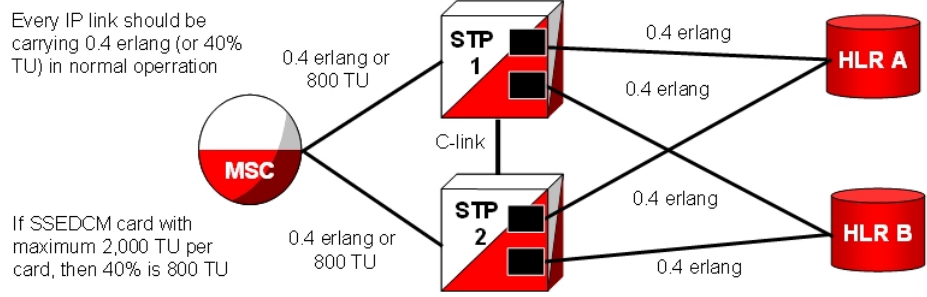
The IPx (IPGWx, IPLIMx, and IPSG) applications can be configured as either an IPLIMx or IPSG supporting M2PA B-, C-, and D-Links; or as an IPGWx or IPSG card supporting A- and E-Links (see the note in M3UA (MTP Level 3 User Adaptation Layer) Protocol for more information about A-links).
Every IP link should carry 0.4 erlang (or 40% TU) in normal operation. For an E5-ENET card with a maximum of 2,000 TU per card, 40% is 800 TU. This scenario is depicted in Figure 5-1.
Figure 5-1 SIGTRAN: Every IP Link at 0.4 Erlang
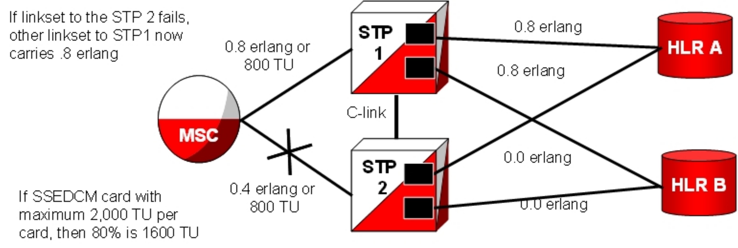
If the linkset to STP2 fails, another linkset to STP1 now carries 0.8 erlang. For an ECDM-A card with a maximum of 2,000 TU per card, 80% is 1,600 TU. This scenario is depicted in Figure 5-2.
Figure 5-2 SIGTRAN: Failover at 0.8 Erlang
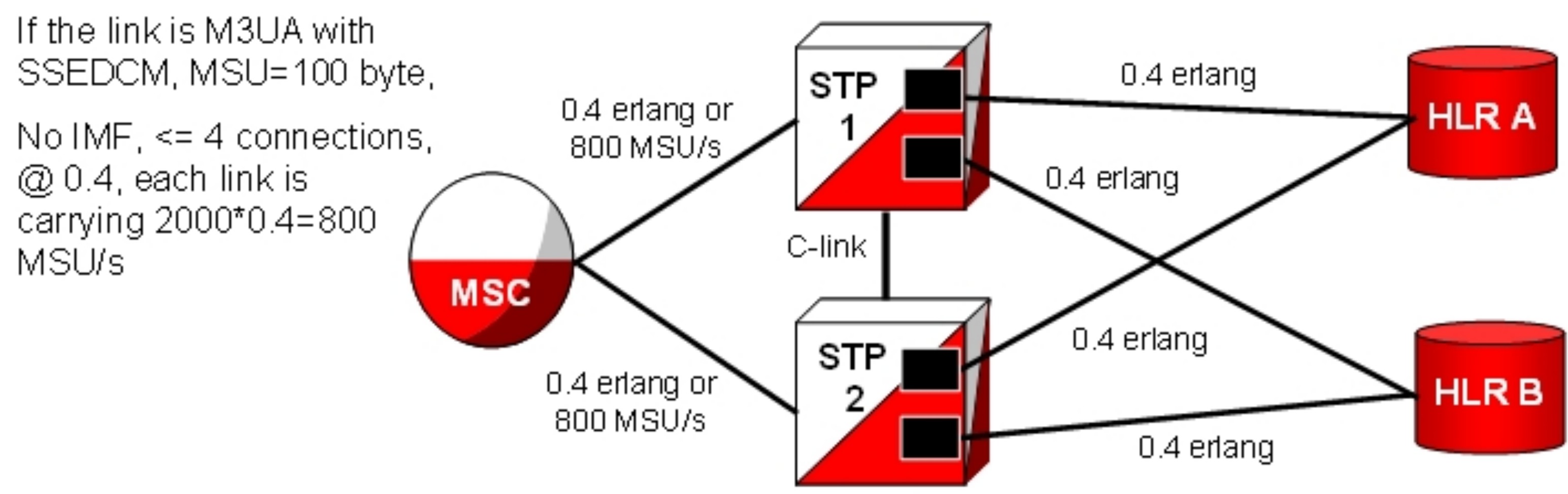
If the link is IPGWx M3UA with an EDCM-A, a 100-byte MSU, no IMF, and 4 or less connections at 0.4 erlang, each link carries 800 MSU/s (2000*0.4). This scenario is depicted in Figure 5-3.
Figure 5-3 SIGTRAN: Every Link at 0.4 Erlang and 800 MSU/s
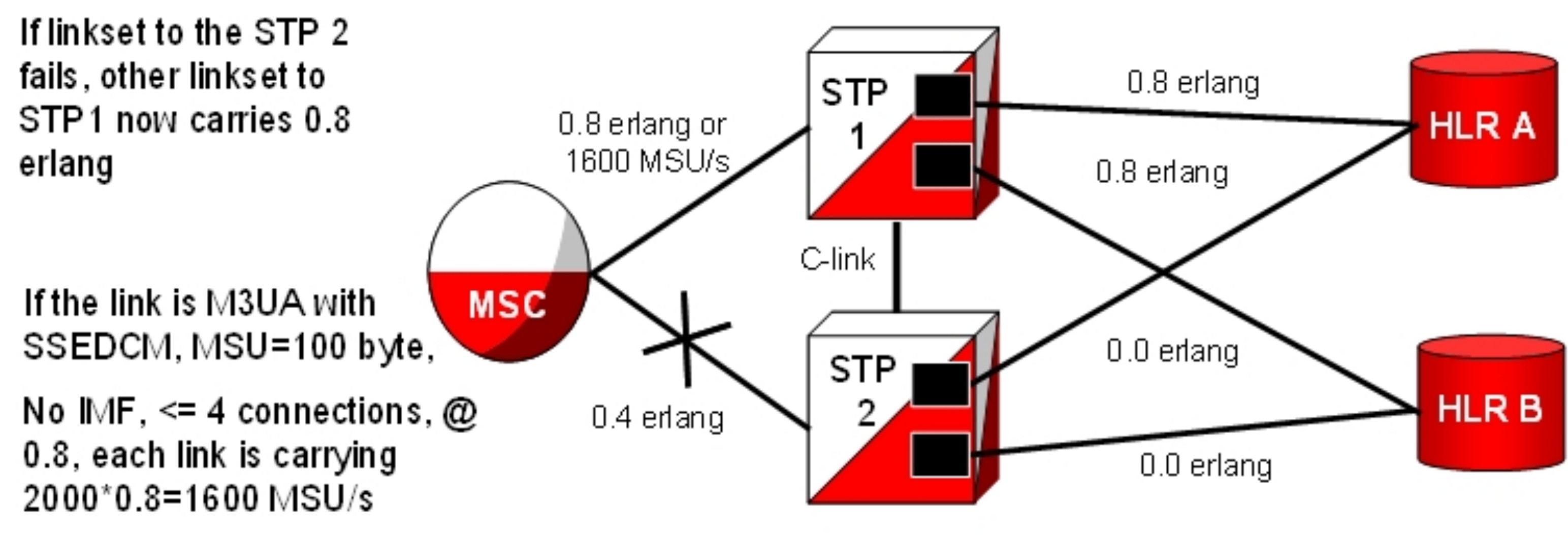
If the linkset to STP2 fails, another linkset to STP1 now carries 0.8 erlang. If the link is IPGWx M3UA with an E5-ENET, a 100-byte MSU, no IMF, and 4 or less connections at 0.8 erlang, each link carries 1600 MSU/s (2000*0.8). This scenario is depicted in Figure 5-4.
Figure 5-4 EAGLE: Failover at 0.8 Erlang and 1600 MSU/s
Calculate the Number of Cards Required
Below are examples of calculations to determine how many cards are needed. These are somewhat simplified; precise calculations require data about the specific network and the traffic running over it.
Example (without monitoring)
Assumptions:
- Mated pair of Signal Transfer Points
- Customer needs 10,000 MSU/s from Mobile Switching Center to Signal Transfer Point
- Average MSU size is 100 bytes/MSU over M3UA
- Less than 5 connections per IP E5-ENET card
- No monitoring is required
Calculation:
- During normal operation, each Signal Transfer Point should handle 5000 MSU/s.
- During failover operation, each Signal Transfer Point should handle 10,000 MSU/s.
- Each E5-ENET over M3UA with up to 4 connections and 100 byte/MSU without monitoring can support 2000 MSU/s.
So 2,000 MSU/s is 1 erlang
40% of 2,000 is 800 MSU/card
To support 5,000 MSU/sec @ 40% rate, 7 cards per Signal Transfer Point are required.
Example (with monitoring)
Assumptions:
- Mated pair of Signal Transfer Points
- Customer needs 10,000 MSU/s from Mobile Switching Center to Signal Transfer Point
- Average MSU size is 100 bytes/MSU over M3UA
- Less than 5 connections per IP E5-ENET card
- Monitoring is required
Calculation:
- During normal operation, each Signal Transfer Point should handle 5000 MSU/s
- During failover operation, each Signal Transfer Point should handle 10,000 MSU/s
- Each E5-ENET over M3UA with up to 4 connections and 100 byte/MSU with monitoring can support 1400 MSU/s
So, 1,400 MSU/s is 1 erlang
40% of 1,400= 560 MSU/card
To support 5,000 MSU/sec @ 40% rate, 9 cards per Signal Transfer Point are required.
IPLIMx linksets are permitted up to 16 links or, if one link per card, 16 cards. linksets are permitted up to 8 links; at one per card, 8 cards are allowed. An Application Server (i.e., in M3UA, a point code) is not permitted to span linkset boundaries, so the prescribed traffic rate would require a different architecture. For example, two Application Servers with different point codes could be used, one with 4 cards and one with 5 cards. A better solution, however, would be to segregate the traffic by type prior to reaching the SS7-over-IP cards, using smaller multiple servers and smaller linksets.
Guidelines for Maximum Provisionable IPSG Cards
- IPSG card hardware type (E5-ENET, E5-ENET-B or SLIC)
- System TPS capacity
- Status of the E5-ENET-B IPSG High Throughput feature
Table 5-23 Guidelines for Maximum Provisionable IPSG Cards
| HIPR2 High Rate Mode Feature | E5-ENET-B IPSG High Throughput Feature | E5-ENET IPSG | E5-ENET-B IPSG | SLIC |
|---|---|---|---|---|
| ON | ON | 150 | 78 | 75 |
| ON | OFF | 150 | 115 | 75 |
| OFF | ON | 100 | 52 | N/A |
| OFF | OFF | 100 | 76 | N/A |
IPGWx Congestion Management Options
There are two options for congestion management: either discard new messages (which is how MTP3 congestion is handled) or fail a connection.
The IPGWx application is designed to match MTP3 congestion procedures. With this option, the connection congestion status is not shared, and altering routing strategy based on congestion events is stopped. Instead, new messages destined to the congested connection are discarded, a new measurement is pegged, and response-method Transfer Controlled (TFC) messages are generated. This routing strategy only changes due to adapter state events.
A configurable timer (False Connection Congestion Timer ) sets the maximum amount of time that a connection can remain congested before it is failed. This timer is similar to the MTP3 False Link Congestion timer (T31).
This Match MTP3 Congestion Procedures option has several advantages: it is simple to implement, prevents mis-sequencing during connection congestion, and notifies the originator of a discarded MSU due to the congestion. The primary disadvantage is that MSUs may be discarded that otherwise may have been transmitted (which is the same as for link congestion).
The configurable UA Parameter Set (UAPS) Timer ‘False Connection Congestion Timer’ allows the user to specify the maximum amount of time an association can remain congested before it is taken out of service. The default setting for the timer is 3,000 ms, the minimum is 0 ms, and the maximum setting (enforced by the IPGWx L2 software, not by the chg-uaps command) is 30,000 ms.
Redundancy and Link Engineering
A properly designed SS7 network always provides at least two physically separate ways to transmit user data. To provide the same level of redundancy using the IP-based solution, node and card redundancy can be used.
The EAGLE can be deployed with completely redundant IP network paths, each of which must be capable of sustaining the worst-case traffic load; or a redundancy model that relies on a mate Signal Transfer Point for IP path redundancy, although this option is less robust (and less expensive).
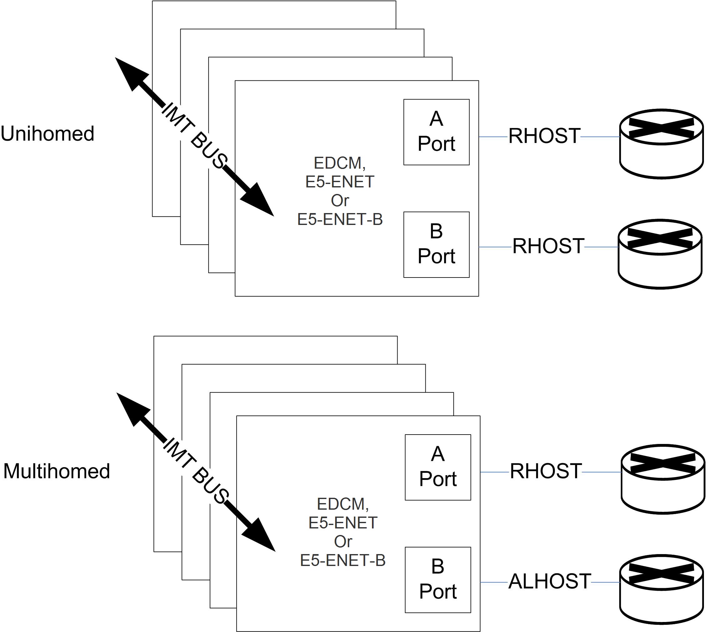
Unihoming versus Multihoming
EAGLE can be deployed with completely redundant IP network paths, each of which must be capable of sustaining the worst-case traffic load. Either of these two methods can be applied, depending on the application used:
- Unihomed links (for M2PA links)
- Multihomed links (for M2PA, M3UA and SUA links)
Unihoming
For unihoming, a set of IPLIMx or IPSG cards, which are configured for worst-case traffic load, hosts one signaling link per linkset. Each signaling link is assigned to a unihomed SCTP association, where half of the associations are assigned to one independent IP network path, and the other half are assigned to another independent IP network path. Each network path must have dedicated bandwidthsufficient to sustain the worst-case traffic load.
Multihoming
For multihoming, a set of IPLIMx or IPSG cards, which are configured for worst-case traffic load, is hosting one signaling link per linkset. Each signaling link is assigned to a multihomed SCTP association, which is mapped to an IP network having at least two completely redundant paths. Each network path must have dedicated bandwidth sufficient to sustain the worst-case traffic load.
Multihoming is very important for M3UA and SUA connections because it is the only means of lossless handover in the event of a path failure.
Multihoming provides network-level resilience for SCTP associations by providing information on alternate paths to a signaling end point for a single association.
SCTP multihoming supports only communication between two end points, of which one or both are assigned with multiple IP addresses on possibly multiple network interfaces. Each IPx card maintains a single static IP route table, utilized by both Ethernet interfaces or ports. By checking the destination address in this IP route table, the router determines the port from which the message is transmitted by the IPx card.
This means that it is not possible to have a route to a single destination from both ports of an IP card – it must be one port or the other. SCTP multihoming does not support communication ends that contain multiple end points (i.e., clustered end points) that can switch over to an alternate end point in case of failure of the original end point.
Figure 5-5 Unihoming versus multihoming
Multi-homing can be used for M2PA links if the M2PA linkset has only one link.
If the M2PA linkset has more than one link, then the value of the M2PA Timer T7 should be lower than RMIN * RTIMES in order for the MTP3 level to trigger a Change Over procedure for MTP3 links.
Note:
RMIN*RTIMES is the minimum time required for an association to restart due to the RTIMES retransmission (via the primary and alternate path in round robin fashion) for an association without receiving any SACK. If the association is closed before the T7 expiration, then the buffer is cleared before the Change Over procedure is triggered by the MTP3 level.Choosing a Redundancy Method for M2PA Links
Unihoming is simpler to configure but more expensive than multihoming, in terms of computational power and network bandwidth to handle worst-case failure. Unihoming requires change-over procedures and rerouting if a network path is interrupted, whereas a multihomed SCTP association will simply switch to the alternate network path.
SCTP multihoming, in general, is less mature than MTP3 change-over procedures. In addition, the lack of ARHOST configurability in the EAGLE can result in asymmetrical traffic on a multihomed connection when both paths are available, which may be undesirable.
The EAGLE fully supports both options for M2PA, but Oracle recommends unihoming.
Mated Signal Transfer Point Redundancy
If a completely redundant IP network path is not available, then a redundancy model that relies on a mate Signal Transfer Point for IP path redundancy is supported by Oracle. This model is less robust but also less expensive.
Figure 5-6 Mated Signal Transfer Point Redundancy
IPGWx mateset
An IPGWx mateset is an IPGWx card linkset configuration with a setting of mated, meaning two IPGWx or IPSG linksets are allowed in a mateset by using the matelsn linkset parameter. The limitation of this approach is that each linkset can have only one card. This configuration for IPGWx is supported to be backward compatible with previous EAGLE software versions.
IPGWx status sharing
Each IPGWx and IPSG card supports up to 50 IP connections, each of which can be available or unavailable for SS7 traffic. Expanding the number of cards in a mateset also means that the worst-case number of status messages to be communicated during run-time grows by the square of the number of cards. The exponential increase in status messages can have a significant impact on IMT bus utilization.
IP destination status
Proper implementation of SS7 network management on behalf of IP-based point codes requires that the cards comprising an IPGWx linkset have a common view of destination availability. Destination availability status is based upon the availability of IP connections assigned to various routing keys. Each card must know which other cards in the linkset have connections available for a given destination. When the total count of available connections for a destination changes from 0 to 1, then a Transfer Allowed (TFA) needs to be generated. When the total count changes from 1 to 0, then a Transfer Prohibited (TFP) needs to be generated.
SS7 network status
IPGWx cards within a mateset must maintain a shared view of SS7 network status and inform IP Signaling Points of changes in this shared view. There are three kinds of SS7 network status:
- SS7 destination availability
- Route congestion status
- User part unavailability
Signaling Link Selection (SLS) Routing
A Signaling Link Selection (SLS) value is a 5- or 8-bit integer (ANSI) or 4-bit integer (ITU) that is used to identify the linkset and link to which a message is to be transported.
The SLS value is included in the SLS field, which is part of the MSU’s MTP routing label. The SLS is used to evenly distribute traffic across routes and links, assuming that the SLS values are randomly distributed by the originating node.
The Oracle Communications SS7-over-IP solution follows standard SLS load sharing with IPLIMx. With IPGWx, SLS values are distributed over the associations in the Application Servers.
LAN/WAN Considerations
- Keep the number of nodes per LAN subnet as low as possible.
The number of nodes attached to a LAN segment is a major influence in overall LAN performance. As the number of nodes increases on a LAN segment, the performance will tend to decrease due to contention for the LAN resource. For optimal performance, this number should be kept as low as possible.
- Be aware of all the node and traffic types on the LAN.
- Dedicate sufficient bandwidth to your IP Signaling traffic.
From the SS7-over-IP perspective, there are two types of nodes: SS7-over-IP-related nodes (which are IP-equipped nodes involved in the overall signaling solution, such as the EAGLE, IP Service Control Points, Media Gateway Controllers and Media Gateways, and any management platforms doing work directly related to the SS7-over-IP solution) and non-SS7-over-IP nodes. Non-SS7-over-IP nodes are any other devices that could be on the LAN using LAN bandwidth, such as file servers or other hosts not directly involved in the signaling solution. If non-SS7-over-IP nodes are deployed on the same LAN as SS7-over-IP nodes, then the nodes share the LAN resources.
- Restrict, or severely limit, the number of non-SS7-over-IP nodes.
If non-SS7-over-IP nodes are on the network, their LAN throughput needs to be well understood, and the worst-case traffic from these sources needs to be considered. Normally it is easier to monitor (baseline) and predict network behavior when the nodes are similar. This is an important factor that will influence network performance.
- Plan for and allocate LAN capacity to handle worst-case scenarios.
Consider all traffic sources and compute worst-case numbers to estimate LAN throughput, including failure scenarios that may switch traffic from one LAN to another. The evaluation of throughput should always be based on the worst-case traffic for each device.
- Monitor LAN performance and make adjustments as necessary.
Once the network is implemented, the LAN throughput and utilization should be monitored for a period of time sufficient to fully understand the traffic on that LAN. Measure the LAN utilization over time and ensure that it is always at an acceptable limit (<= 35 percent of maximum LAN throughput).
- Once the network is implemented, the RTT should be checked.
Confirm that the RTT is appropriate to achieve the maximum desired throughput, and that the RTT is acceptable from the viewpoint of the applications that are originating the traffic.
IP network planning must be executed carefully to realize the benefits of SS7-over-IP deployments. Oracle can assist with characterizing your LAN/WAN QoS parameters and engineering an SS7-over-IP solution. Contact your Oracle Sales Representative for more information related to this Professional Service.
Retransmission Concept
The Oracle-recommended IP network environment for signaling traffic has:
- RTTs set according to traffic (see Refine RTO Parameter)
- Minimal errors (< 0.01%)
- Minimal jitter
A transport protocol provides transport reliability through two mechanisms:
- Explicit Data Acknowledgements: the sending side retains transmitted data until the receiving side explicitly acknowledges its receipt
- Retransmission Timer: the sending side maintains a timer, and if the timer expires prior to receiving an acknowledgement for the transmitted data, then the sender will “retransmit” the data to the receive end
Retransmissions and Destination Status
When transmitting data on a multihomed association, the initial transmission is made to the primary address on the primary path. If the initial transmission times out, then the first retransmission is made to an alternate destination in a round-robin, consecutive fashion. The SCTP layer will continue to send the initial transmission of new data arriving for transmission from upper layers on the primary path.
If a unihomed SCTP endpoint is not in contact after RTIMES errors, the end point address is marked as unreachable. For multihomed associations, if an endpoint’s address is not in contact after RTIMES/2 errors, the address is marked as unreachable.
An error is a failure to Selectively Acknowledge (SACK) a transmitted packet or acknowledge a heartbeat within a Retransmission Time Out (RTO). Alternate paths exchange heartbeats as a means of confirming connectivity, and failure to acknowledge heartbeats would cause an alternate destination to be marked as unreachable.
SCTP Timers
Oracle provides two retransmission modes: RFC and Linear. The SCTP retransmission control feature allows the tailoring of retransmissions to detect a network fault in a timely fashion through these configuration parameters:
- RMODE: Selects desired retransmission mode (RFC or LIN)
- RTIMES: Maximum number of retransmits attempted before the connection is declared lost (3 to 12); the default is 10
- RTO: Time to wait before the current retransmit attempt is declared a failure. This time is dynamic because it is a moving average of the network
- RMAX: Upper bound of calculated RTO (10 ms to 1,000 ms); the default is 800; Oracle suggests 3 * RMIN
- RMIN: Lower bound of calculated RTO (10 ms to 1,000 ms). The default is 120; Oracle suggests the greater of (1.2 * average RTT) or (10 ms + average RTT).
- CWMIN: Minimum Congestion Window Size (1,500 to 192K); the default is 3K
RFC Timer Setting
With an exponential timer setting, the RTO value is doubled for each retransmit attempt. When transmitting a packet, the RTO has to expire before attempting to retransmit. With the second attempt, the last RTO value is doubled (RTO * 2) before retransmitting; with the third attempt, the last RTO value is doubled again (RTO * 4); and so on. This method significantly increases the time to determine that a link is lost.
For example, if data is being transmitted for five retransmits, the time to determine a lost link is:
RTO.min * Path.Max.Retransmits (or 1 + 2 + 4 + 8 + 16 + 32) = 63 sec
Table 5-24 shows RFC timers and their RFC and Oracle-recommended default values.
Table 5-24 SCTP Configuration Data Descriptions for Oracle EAGLE
| RFC Name | Description | RFC Recommended Default Value | Oracle Default Value | Oracle Configurable? | Oracle Ranges |
|---|---|---|---|---|---|
| RTO.initial |
Initial RTO Value |
3 seconds | 120 ms |
Yes Assoc RMIN parameter |
1-1000 ms |
| RTO.max | Upper limit of RTO | 60 seconds | 800 ms |
Yes Assoc RMAX parameter |
1-1000 ms |
| RTO.min | Lower limit of RTO | 1 second | 120 ms |
Yes Assoc RMIN parameter |
1-1000 ms |
| Max.Init. Retransmits | Maximum Initial Retransmit Attempts | 8 attempts | 10 attempts |
Yes Assoc RTIMES parameter.Not configurable independently of Assoc.max. retrans |
1-12 |
| Association. max. retrans | Maximum Association Data Retransmit Attempts | 10 attempts | 10 attempts |
Yes Assoc RTIMES parameter |
1-12 ms |
| Path.max. retrans | Maximum Data Retransmit attempts per Destination (used for multi-homing only) | 5 attempts | 5 attempts | Indirectly ½ of the assoc RTIMES parameter | 1-6 ms |
| Acknowledge- ment timer | SACK Transmit | User Configurable not to exceed 500 ms | ½ RTO or 200 ms, whichever is less |
Indirectly RTO is bound by the assoc RMIN and RMAX parameters |
5-200 ms |
| T3-rtx | Timer Data Retransmit |
RTO (see RTO.initial for initial value ) |
RTO
(see RTO.initial for initial value) |
Yes RTO is bounded by the assoc RMIN and RMAX parameters |
10-1000 ms |
| T1-init | Timer Init retransmit timer |
Initially 3 seconds RTO thereafter |
Initially 1 second, RTO thereafter |
No for initial value Indirectly thereafter via RMIN/RMAX bounding of RTO |
10-1000 ms |
| HB.Interval | Heart Beat Interval | 30 seconds |
RTO+500 ms |
Yes RTO + Assoc HBTIMER parameter |
RTO+500 ms to RTO+10000 ms |
| Shutdown timer | Shutdown timer t2 | RTO | RTO |
Indirectly RTO is bound by the assoc RMIN and RMAX parameters |
10-1000 ms |
| Cookie Timer | Cookie-t1 – Cookie Echo retransmit timer |
Initially 3 seconds RTO thereafter |
Initially 1 second RTO thereafter |
No for initial value Indirectly thereafter via RMIN/RMAX bounding of RTO |
10-1000 ms |
| Cookie life | Cookie Life | 60 seconds | 5 seconds | No | 5 seconds |
Note:
SCTP Heart Beats (HBs) are sent after every HB interval on an idle path of the SCTP association. If more than one idle path exists, then HBs are sent alternately on each idle path, after each HB interval.LIN Timer Setting
Oracle has implemented a more aggressive timer method called Linear (LIN), in which the RTO between attempts is constant. Oracle recommends this setting to detect a failure more quickly than the RFC method.
With the LIN timer setting, the time to declare the association down is at least
RMIN * RTIMES
For very high-throughput associations, RTIMES (and if possible, RMIN) should be lowered and CWMIN increased. CWMIN is the parameter that sets the minimum size of the congestion window, which determines the number of packets that can be sent without having received the corresponding ACK packets.
On the far end, the LIN mode can coexist with RFC mode, but in contrast to the Signaling Gateway, the far-end may experience congestion in the ASP-to-SGP direction because of network impairments.
Jitter Effects
Since the RTO is a moving average of network RTT samples, as the jitter range increases, bounding the lower limit of the RTO at or near the average will cause the amount of unnecessary retransmissions to increase, since for each transmission that takes longer than the current RTO to acknowledge a retransmission will occur, wasting bandwidth..
If the lower limit of the RTO is bounded to the upper end of the jitter range to minimize retransmits, then connection failure detection time is similarly increased.
So, minimizing jitter in the network translates into a small range for network RTT, and the RTO can be bounded to minimize retransmissions while being able to detect a loss of connection in a timely fashion.
Configure Congestion Window Minimum (CWMIN) Parameter
The CWMIN parameter is important in managing traffic flow and retransmissions under varying network conditions. Changing the congestion window by setting CWMIN to a higher value affects how long it takes to recover from the retransmit event. This limits how far the window gets closed in a retransmit-event condition. In the extreme case, one could set CWMIN to the configured buffer size, which allows the entire buffer bandwidth to be used. As a general rule, setting CWMIN to a value equal to half of the traffic rate in an RTT interval should allow adequate retransmit-recovery time while preventing excessive load to the peer.
CWMIN = (Bytes/Sec * RTT) / 2 bytes
Note:
Setting CWMIN to a value much higher than MTU will result in periodic intermediate node overloads. CWMIN can’t be set less than 3K and should not exceed the remote peer reception window (Advertized Reception window). When possible CWMIN is normally set to ~64K or greater. The specific value chosen for the sender should take into account network latency, configuration, packet loss, capacity, and traffic characteristics. It is important that RMIN be set to a value greater than the expected average RTT to minimize false retransmissions. CWMIN could be set to a value between 10% and 20% of the remote peer Reception window.