6 Implementation
This chapter provides hardware information, high-level configuration steps for the IPLIMx, IPGWx, and IPSG applications, how to refine timers and parameters after the installation, and high-level system verification steps.
Hardware requirements
Some of the hardware requirements specific for a Oracle Communications SS7-over-IP network are described here. However, for a full list customized for your planned network, contact your Sales Representative.
EAGLE
An EAGLE fully configured for SS7-over-IP consists of at least one IPLIMx, IPGWx, or IPSG application. The applications can be installed on an E5-ENET, E5-ENET-B or SLIC card.
Two HIPR2 cards are required in shelves equipped with E5-ENET or E5-ENET-B cards. If HIPR2 cards are installed, all other shelves must be equipped with all HIPR2 cards in one shelf.
Table 6-1 shows the cards and their Advertised Capacity in TPS.
Table 6-1 EAGLE IP Signaling Maximum Capacities by Card and Application
| EAGLE Card Name | IPLIMx Capacity | IPGWx Capacity | IPSG Capacity |
|---|---|---|---|
| E5-ENET | 4,000 | 4,000 | 5,000 |
| E5-ENET-B (E5-ENET-B when IPSG High Throughput Feature OFF, E5-ENET or SLIC) | 4,000 | 4,000 | 6,500 |
| E5-ENET-B (E5-ENET-B IPSG High Throughput feature ON) | 4,000 | 4,000 | 9,500 |
| SLIC (IPSG High Throughput feature OFF) | 4,000 | 4,000 | 12,000 |
The capacities listed in this table are achieved when the traffic carried by the application involves no feature or network attribute that requires excessive CPU, memory, or transport capacity. Rates in excess of the values shown will result in signaling link or IP connection congestion.
Integrated Message Feeder (IMF)
When monitoring IPx links using IMF, Oracle requires that HIPR2 cards and at least one STC card are configured on the same shelf as the IPx cards. Only M2PA links that are RFC 4165 compliant can be monitored. A minimum of two STC cards are required per system to turn on the monitoring feature in the EAGLE.
The E5IS Data Feed or monitoring subsystem requires a significant amount of CPU and memory resources from the IPx cards when monitoring M2PA, M3UA and SUA links. When enabled, this capability causes the of the IPx applications to drop well below the maximum capacity of the platform. For a detailed analysis of IP7 throughput for provisioning purposes, refer to Engineering Rules for Determining IP7 Application Throughput.
Installation of the SS7-over-IP system includes both hardware installation and software provisioning, and is detailed in the EAGLE customer documentation.
Converting Non-IPSG-M2PA Linksets to IPSG-M2PA Linksets
IPSG-M2PA signaling links can reside in a linkset with other non-IPGWx, non-IPSG-M2PA links. Having non-IPSG-M2PA links in a IPSG-M2PA linkset is supported to allow non-IPSG-M2PA linksets to be converted to IPSG-M2PA linksets, and should be a temporary condition. In the case of IPSG-M2PA linksets that contain other link types, the non-IPSG-M2PA links will not be subject to the configured SLKTPS. The rept-stat-iptps command will not report any link IP TPS data or raise link IP TPS alarms for the non-IPSG links that are not reporting IP TPS information.
To convert an existing non-IPSG-M2PA linkset to an IPSG-M2PA linkset, perform the following steps:
- Existing linkset (
LINKSETA) with IPGWAPC=NO and IPSG=NO (i.e. contains links of any type except IPGW or IPSG) - Enter
chg-ls:lsn=LINKSETA:ipsg=YES:slktps=XXXX - Provision new IPSG cards and M2PA associations
- Add new IPSG-M2PA links to linkset and remove non-IPSG-M2PA links from linkset, soaking modifications as required
To back out the above conversion:
- Remove IPSG-M2PA links from linkset and add original non-IPSG-M2PA links to linkset.
- Enter
chg-ls:lsn=LINKSETA:ipsg=NO
Using the chg-card Command to Migrate IPLIM to IPSG
The chg-card command allows the IPLIM application running on E5-ENET or E5-ENET-B cards, to be migrated to IPSG, if the following requirements are met:
- The IPLIM application must be running on E5-ENET or E5-ENET-B cards.
- The hardware can be changed to IPSG running on E5-ENET or E5-ENET-B cards.
- The card must be manually inhibited prior to successful execution of the change command.
- All IP associations configured for the card must use adapter type M2PA.
- All links configured for the card must have an association configured.
- The migrated IPSG card TPS and system TPS must pass limit checks.
- The card must be manually allowed after successful execution.
Note:
If changing the configuration from IPLIM to IPSG exceeds the Transactions per Second (TPS) limits of the card or system, then the command is rejected.Converting IPGWx M3UA Application Servers to IPSG-M3UA Linksets
IPGWx links and IPSG-M3UA links cannot co-exist in the same linkset for the following reasons:
- IPGWx linksets require provisioning of Routing Keys and Application Server (AS) table entries in the EAGLE to communicate with M3UA ASs; IPSG-M3UA linksets require only SS7 routes, since the IPSG-M3UA linkset defines the scope of the AS
- The M3UA AS’s point code is a non-adjacent route accessed by a provisioned EAGLE Routing Key for an IPGWx linkset; this point code is the adjacent point code of an IPSG-M3UA linkset. This results in significant differences in network management behavior between IPGWx and IPSG-M3UA
- IPSG implements IP TPS control with subtle differences from IPGWx that result in incompatibilities
- The Routing Key(s) used by the M3UA AS must be DPC-only; or the use of DPC-only Routing Key(s) would not degrade current or planned capability
- The M3UA AS-Pending procedure using a non-zero value for T (recovery) must not be a critical function provided by the Signaling Gateway
- M3UA ASP Failure notifications must not be a critical function provided by the Signaling Gateway
- The number of IPGWx-M3UA Application Servers to be converted to IPSG-M3UA linksets must not result in the total EAGLE link or linkset limits being exceeded. A maximum of 2,000 links and 1,024 linksets are supported.
- IPGWx cards that will be redeployed as IPSG cards MUST be E5-ENET or E5-ENET-B cards.
- The number of Routing Keys and ASs provisioned on the IPGWx linkset being converted
- The IPGWx redundancy model used
- The connected AS’s reliance on AS procedures
- The connected AS’s maximum supported number of connections and attached Signaling Gateways
The chg-card command allows the IPLIM application running on E5-ENET, E5-ENET-B, or SLIC cards to be migrated to the IPSG application, if the following requirements are met:
- The IPLIM application must be running on an E5-ENET, E5-ENET-B or SLIC card.
- The hardware can be changed to IPSG running on E5-ENET, E5-ENET-B cards or SLICs.
- The card must be manually inhibited prior to successful execution of the change command
- All IP associations configured for the card must use adapter type M2PA.
- Al links configured for the card must have an association configured.
- The migrated IPSG card TPS and system TPS must pass limit checks.
- The card must be manually allowed after successful execution.
Note:
If changing the configuration from IPLIM to IPSG exceeds the Transactions per Second (TPS) limits of the card or system, then the command is rejected.If the chg-card command will not be used, then it is highly recommended that ProComm scripts or other automated EAGLE provisioning functionality be used to further mitigate risk.
IPGWx to IPSG-M3UA Conversion Example 1
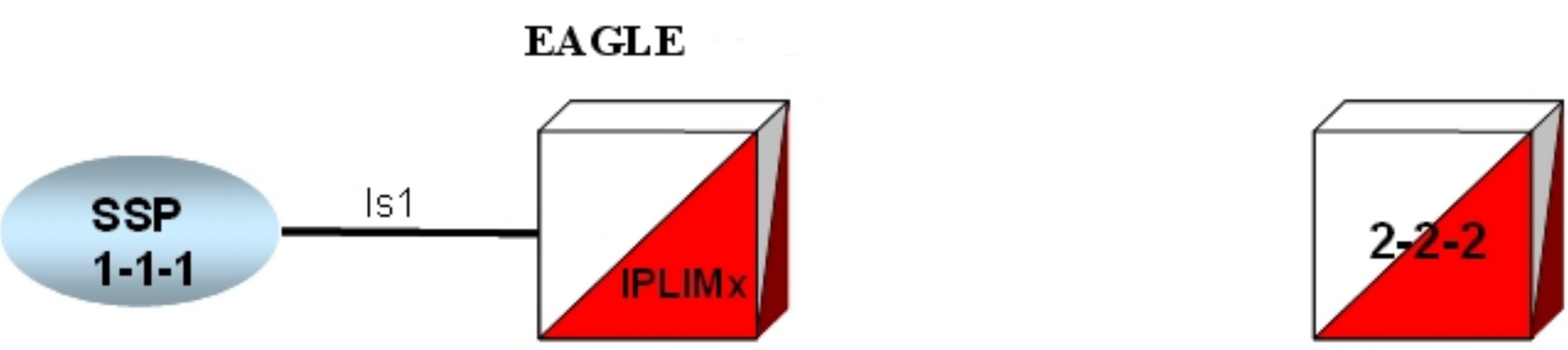
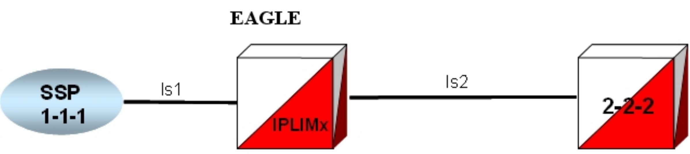
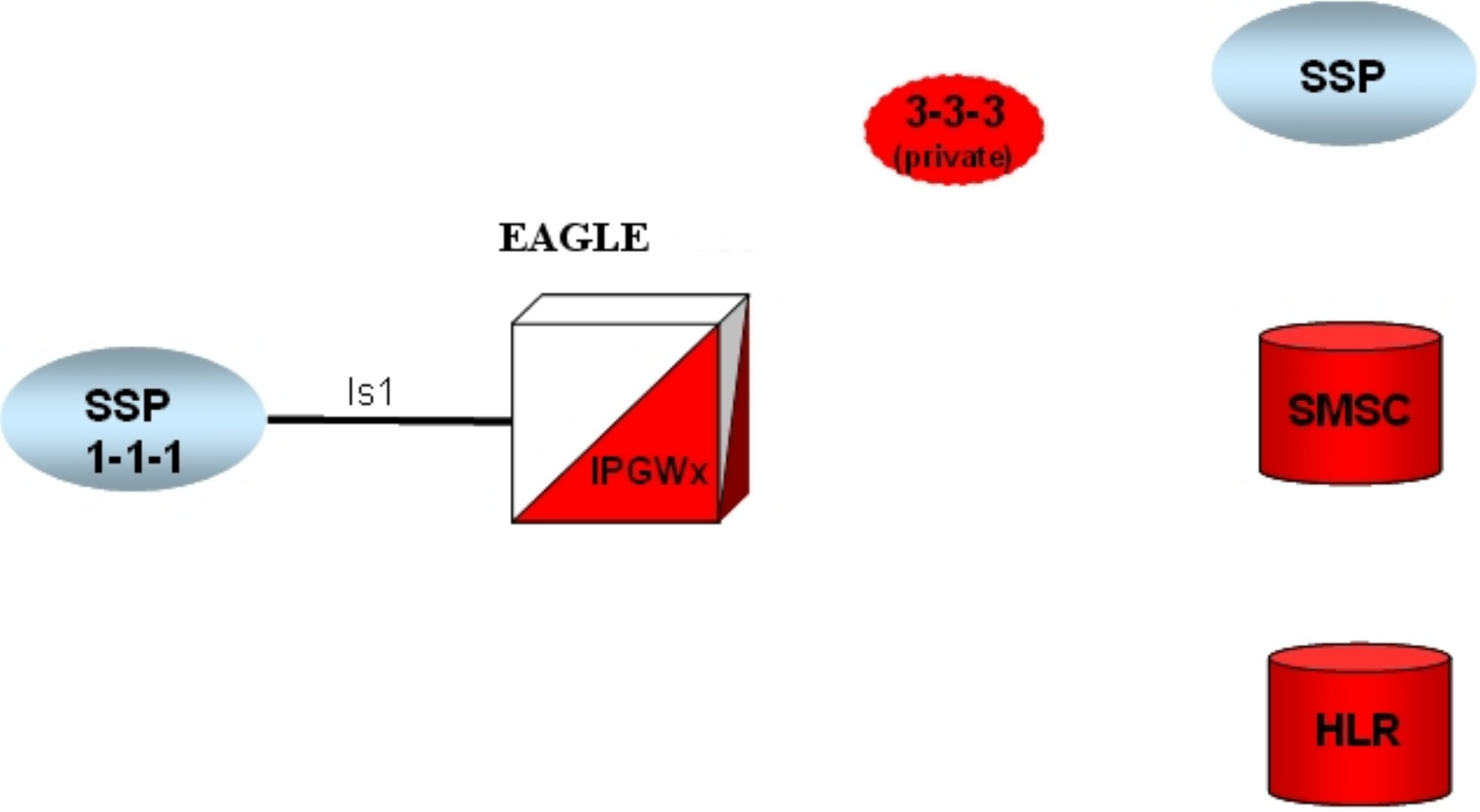
Figure 6-1 depicts one strategy to convert a simple IPGWx deployment to IPSG-M3UA.
Figure 6-1 IPGWx to IPSG-M3UA Conversion Strategy Example 1
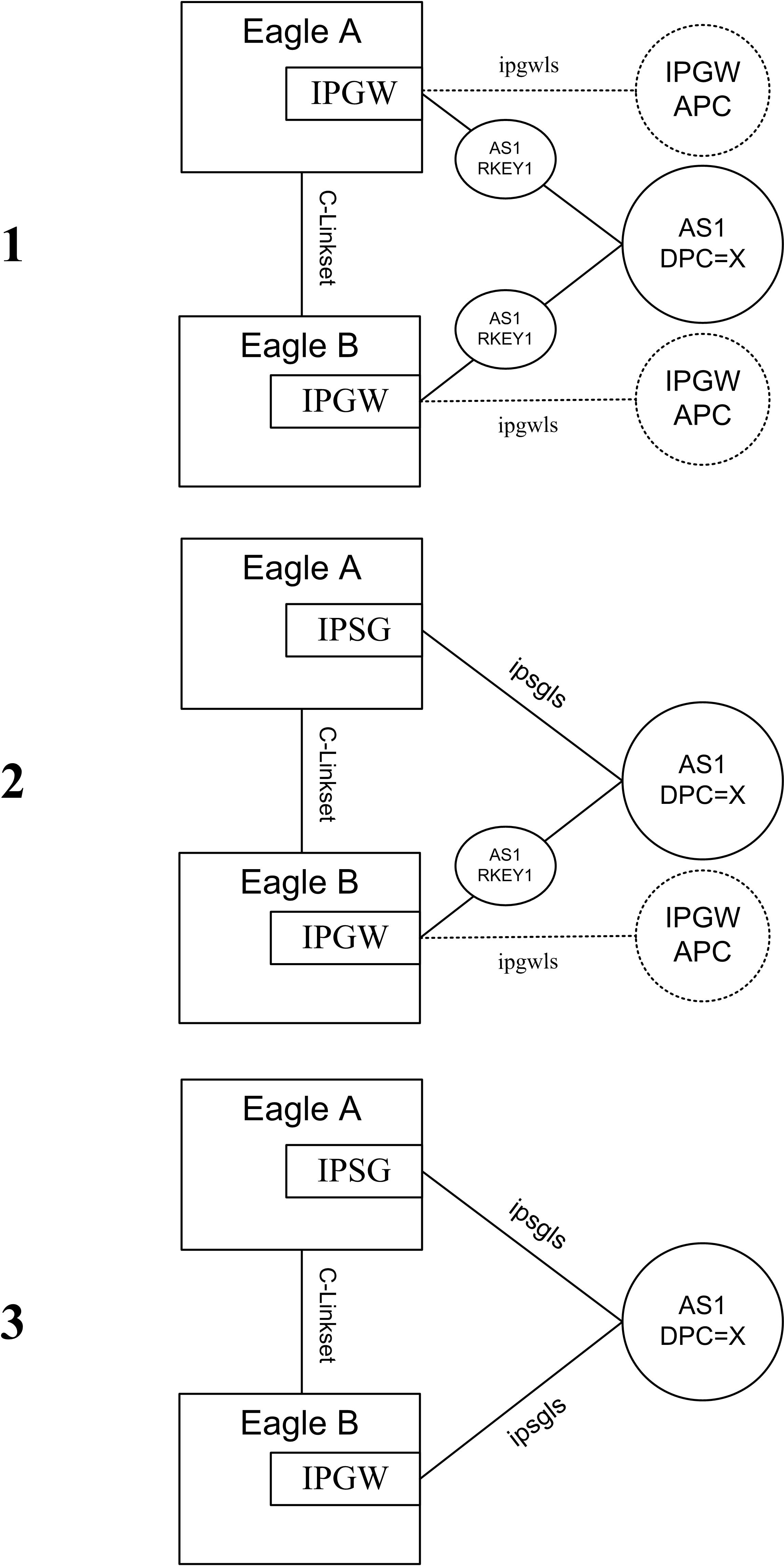
- Each STP in the mated pair of STPs utilizes a single IPGWx card to provide connectivity to AS1
- Each IPGWx card hosts a single M3UA association referenced by AS1
- AS1 is referenced by a single DPC-only Routing Key with DPC=X in each STP
- The IPGWx signaling link in the top EAGLE is gracefully removed from service.
- The Routing Keys for AS1/DPC=X and AS1 are deleted from the EAGLE database.
- The M3UA association settings are recorded for use when the association is re-entered on the IPSG card.
- The M3UA association is deleted from the EAGLE database .
- The SS7 routes to DPC X and the IPGWx APC are deleted from the EAGLE database.
- The IPGWx Signaling Link and Linkset is deleted from the EAGLE database.
- The IP-CARD, IP-LNK, and IP-RTE settings for the IPGWx card are recorded. These settings are not preserved when the IPGWx card is deleted.
- The IPGWx card is deleted from the EAGLE database and entered as an IPSG card (assumes that there is an E5-ENET, E5-ENET-B or SLIC card in the slot).
- The IP-CARD, IP-LNK, and IP-RTE entries are updated in the EAGLE database for the new IPSG card with the setting recorded for the IPGWx card prior to its deletion.
- An M3UA association is entered into the EAGLE database and is updated with any non-default settings recorded for the IPGWx association prior to its deletion.
- A new IPSG-M3UA linkset with APC=X is provisioned in the EAGLE database with the appropriate SLKTPS.
- A single IPSG-M3UA SLK is added to the IPSG-M3UA linkset referencing the M3UA association that is hosted by the IPSG card.
- An SS7 route to DPC X over the IPSG-M3UA linkset is entered into the EAGLE database. The relative cost of this route is determined by the customer’s requirements and approach to proving and soaking the IPSG-M3UA link. Initially, it may be desirable for the cost of the route over the IPSG-M3UA linkset to be higher than the cost of the route over the C-linkset; however, it should be noted that this approach will not prevent the AS from sending SS7 traffic over the IPSG-M3UA link once the IPSG-M3UA link becomes IS-NR.
- The IPSG-M3UA association is opened and SCTP connectivity is confirmed. The state of the IPSG-M3UA SLK should be
OOS-MT-DISABLED. The state of the AS-ASP instance should be ASP-INACTIVE, assuming the ASP is not administratively blocked at the AS. - The IPSG-M3UA SLK is activated; it's state should become IS-NR. The state of the AS-ASP instance should be ASP-ACTIVE, assuming the ASP is not administratively blocked at the AS.
- The cost of the SS7 route to DPC X in EAGLE A is adjusted as appropriate to allow/prevent EAGLE A from using the IPSG-M3UA linkset to deliver MSU traffic destined for DPC X.
The configuration shown in #3 of Figure 6-1 is a result of utilizing the same steps used in EAGLE A to convert the IPGWx linkset in EAGLE B to IPSG-M3UA.
IPGWx to IPSG-M3UA Conversion Example 2
Figure 6-2 depicts one strategy to convert a more complex IPGWx deployment to IPSG-M3UA.
Figure 6-2 IPGWx to IPSG-M3UA Conversion Strategy Example 2
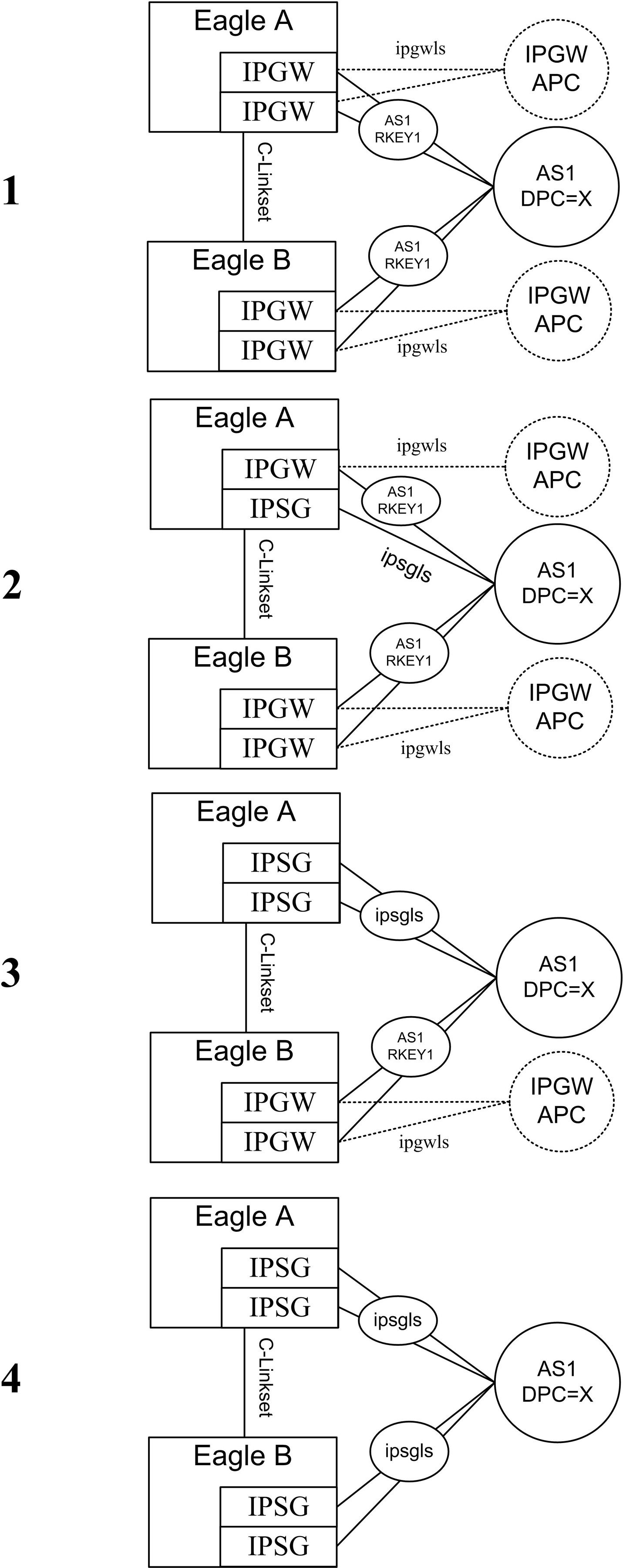
It should be noted that the IPGWx deployment shown in #1 of Figure 6-2 has the following attributes:
- Each STP in the mated pair of STPs utilizes two IPGWx cards to provide connectivity to AS1
- Each IPGWx card hosts a single M3UA association referenced by AS1
- AS1 is referenced by a single DPC-only Routing Key with DPC=X in each STP
The configuration shown in #2 of Figure 6-2 is a result of re-provisioning one of the IPGWx cards in EAGLE A to be a single-link IPSG-M3UA linkset with an APC of X, while leaving one of the original IPGWx links in place. From the M3UA AS’s perspective, provisioning the IPSG-M3UA link in EAGLE A while the remaining IPGWx links in EAGLE A and EAGLE B are still provisioned may be viewed as:
- Effectively connecting a third Signaling Gateway to the AS; this will be true if the AS relies on AS Notifications to operate correctly, since EAGLE treats AS1 over IPGWx linkset as a separate AS than AS1 over the IPSG-M3UA linkset.
OR
- No configuration change; this will be true if the AS does not rely on AS Notifications to operate correctly. In this case, AS notifications sent by EAGLE A are ignored by the AS and the IPSG-M3UA link is simply used as a path to the SS7 network if it is ACTIVE. The fact that the AS notifications sent by EAGLE A are not scoped across the IPGWx and the IPSG-M3UA linkset is not applicable. For ASs with this attribute, it may be desirable to disable AS notifications on the IPSG-M3UA linkset by setting the asnotif linkset parameter to NO.
Similar to the earlier example, the relative cost of the route to DPC X over the IPSG-M3UA linkset in #2 of Figure 6-2 is dependent on the customer’s cutover strategy. It is important to note here again that the AS may begin sending SS7 traffic over the IPSG-M3UA link once the ASP becomes ACTIVE and the IPSG-M3UA link becomes IS-NR regardless of the relative cost of this route in the EAGLE.
The configuration shown in #3 of Figure 6-2 is a result of re-provisioning the remaining IPGWx card in EAGLE A to be an IPSG card hosting a single IPSG-M3UA link and adding the link to the existing IPSG-M3UA linkset connected to AS1. From the AS’s perspective, this change may be viewed as 1) reducing the number of connected Signaling Gateways back to the original two OR 2) no change. In either case, once the second IPSG-M3UA link is brought into service in EAGLE A, conversion activities are complete for EAGLE A.
The configuration shown in #4 of Figure 6-2 is a result of performing the same steps in EAGLE B as described for EAGLE A in steps #2 and #3.
IPGWx to IPSG-M3UA Conversion Example 2A
Figure 6-3 depicts an alternative strategy to convert the IPGWx configuration from the one described in IPGWx to IPSG-M3UA Conversion Example 2 to IPSG-M3UA.
Figure 6-3 IPGWx to IPSG-M3UA Conversion Strategy Example 2A
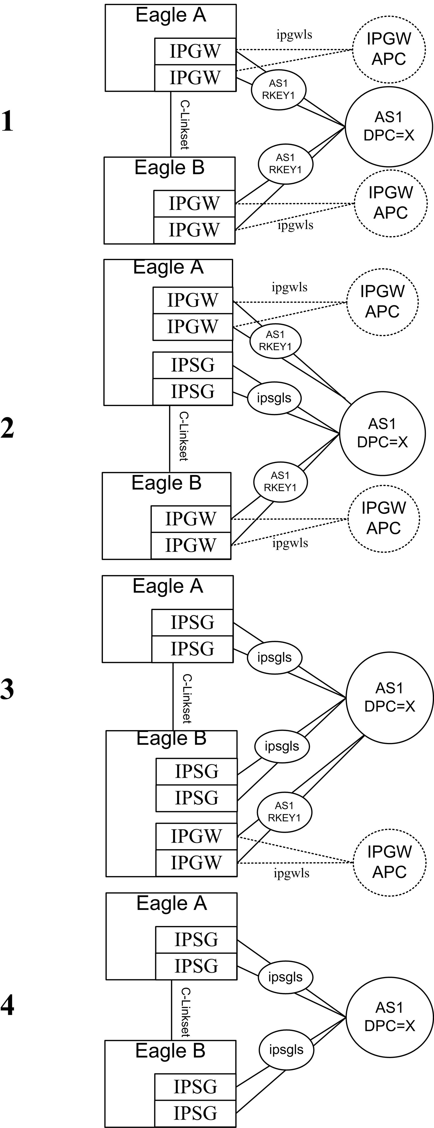
The strategy shown in Figure 6-3 can be used to minimize risk and increase the flexibility in switching traffic between the IPGWx and IPSG-M3UA links and is dependent on:
- The customer’s willingness and ability to provision new E5-ENET, E5-ENET-B or SLIC cards and associated cabling and network connectivity for the IPSG links while leaving the existing IPGWx cards and associated cabling and network connectivity in place during the soak period
- The AS’s ability to support the configuration shown in #2 and #3 of Figure 6-3. As described earlier, the IPSG-M3UA linksets may be viewed by the AS as additional Signaling Gateway instances or simply additional M3UA connections to the SS7 network.
In #2 and #3 of Figure 6-3, the SS7 route cost for the routes to DPC X over the IPGWx linkset, the IPSG-M3UA linkset, and the C-linkset provides maximum control over which path is used to deliver MSUs destined for DPC X to the M3UA AS. It should be noted that multiple-link IPGWx linksets were not designed to be in combined linksets (i.e having SS7 routes to the connected ASs with equal cost to other SS7 routes in the same EAGLE) and so there exists the potential for the loadsharing across associations in a multiple link IPGWx linkset to be uneven when the IPGWx and IPSG-M3UA route costs are the same, especially if one or more SLKs or connections is not IS-NR.
Configuration
This section describes the configuration sequence for the IPLIMx, IPGWx and IPSG applications.
Note:
As of Release 44.0, all Ethernet ports are OFF by default. The in-service port and associated light will be turned ON by running the relevant application. The light for the unused port will remain OFF.Configure the IPSG Application
- Enter adjacent point code (
ent-dstn).
- Define capacity and use alarm (ent-ls).ent-ls:lsn=ls1201:apc=10-10-10:lst=a:adapter=m3ua:ipsg=yes:rcontext=1:slktps=100
- Enter route (
ent-rte).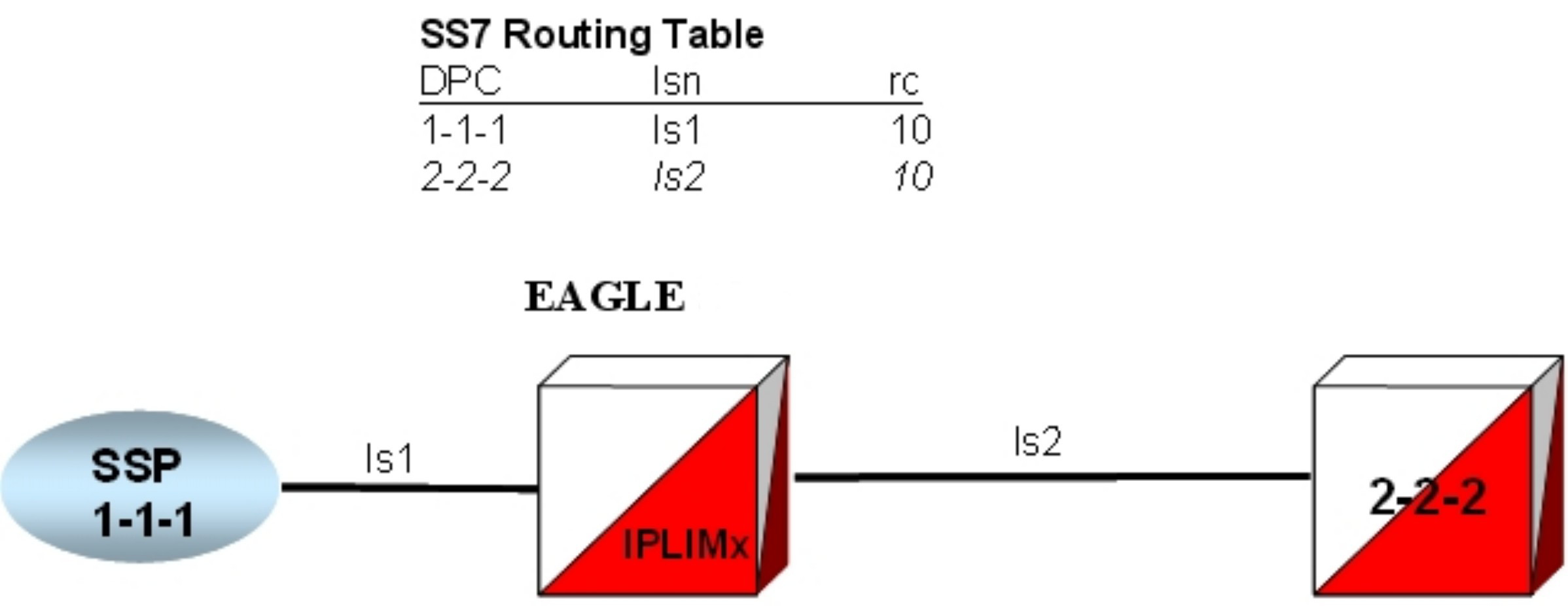
Configure the IPSG Application on the Same Card
- Enter route (
ent-rte).
Configure the IPLIMx Application
- Declare the DCM to be iplim or iplimi (
ent-card).
- Enter adjacent point code (
ent-dstn).
- Define capacity and use alarm (
ent-ls).
- Enter route (
ent-rte).
Configure the IPGWx Application
This section provides a basic overview of the steps involved to provision the IPGWx application for M3UA. For detailed procedures, see Database Administration - IP7 User's Guide of your current EAGLE documentation suite.
- Declare the E5-ENET or E5-ENET-B to be ipgwx (
ent-card).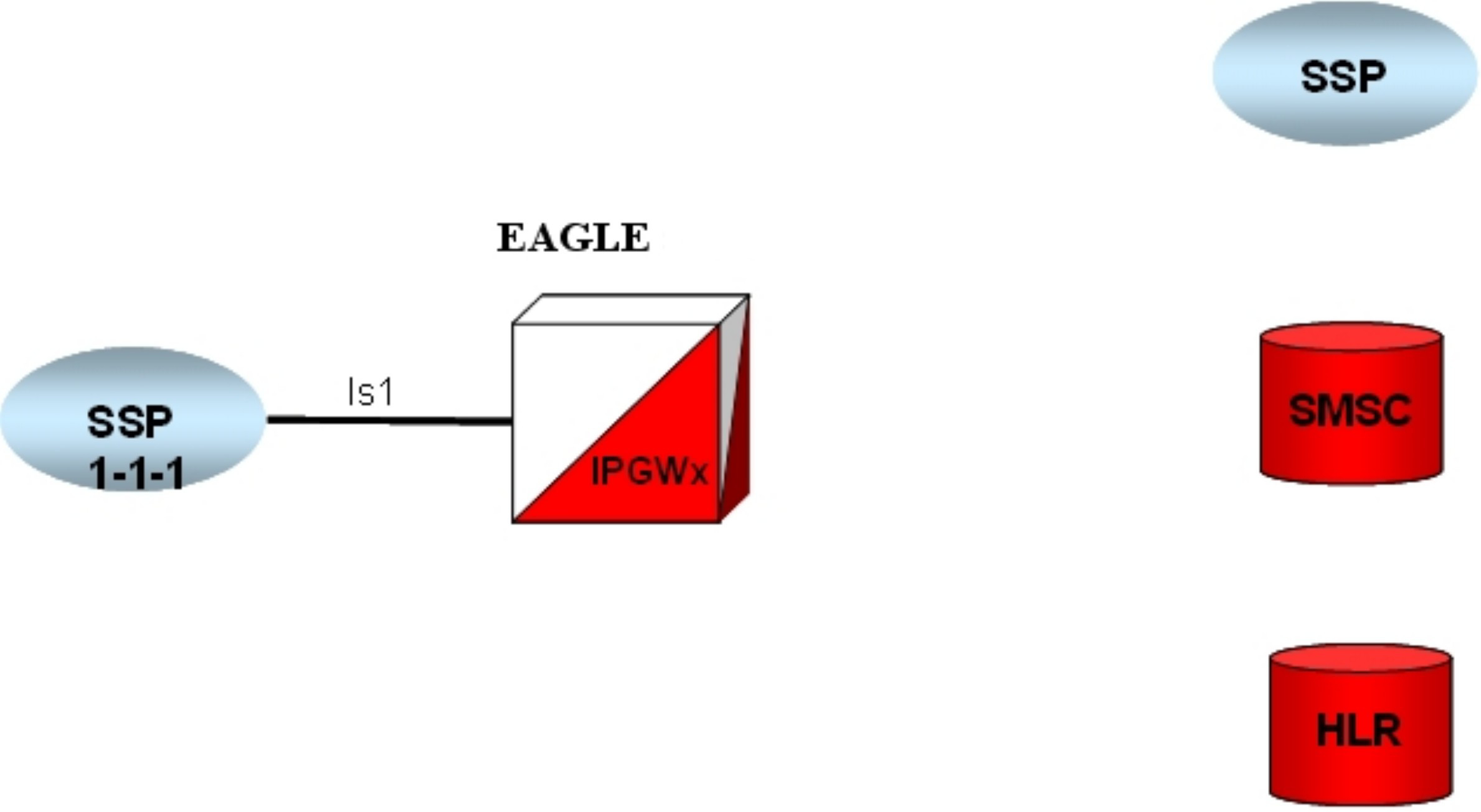
- Enter the virtual point code (
ent-dstn).To create a virtual IPGWx SS7 link, first create an SS7 linkset and an Adjacent Point Code (APC).
The adjacent node functionality for an IPGWx linkset is performed by the IPGWx software to provide SS7-to-IP interworking. For this reason, IPGWx APCs are referred to as “adjacent” point codes. Syntaxes that are normally not allowed for point codes, such as 0-0-1, are allowed for virtual adjacent point codes to minimize depletion of point code space. In addition, beginning with EAGLE 34.0, private point codes can be utilized (and are recommended by Oracle Communications) for IPGWx APCs. Private point codes are used for internal routing within the EAGLE and are not known outside of the EAGLE. By making APCs private, it is possible to have a point code value indicated as private and still have the same point code value (as not private) available for network configuration.
- Define bandwidth and use alarm (
ent-ls).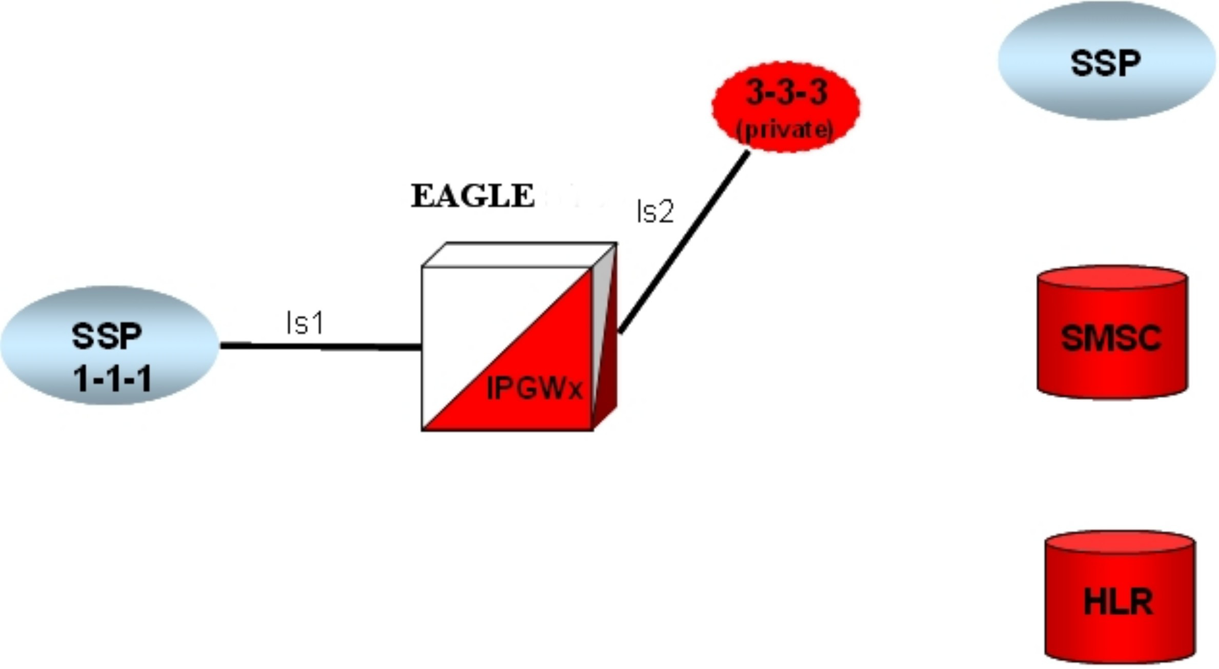
- Enter SEP point codes (
ent-dstn).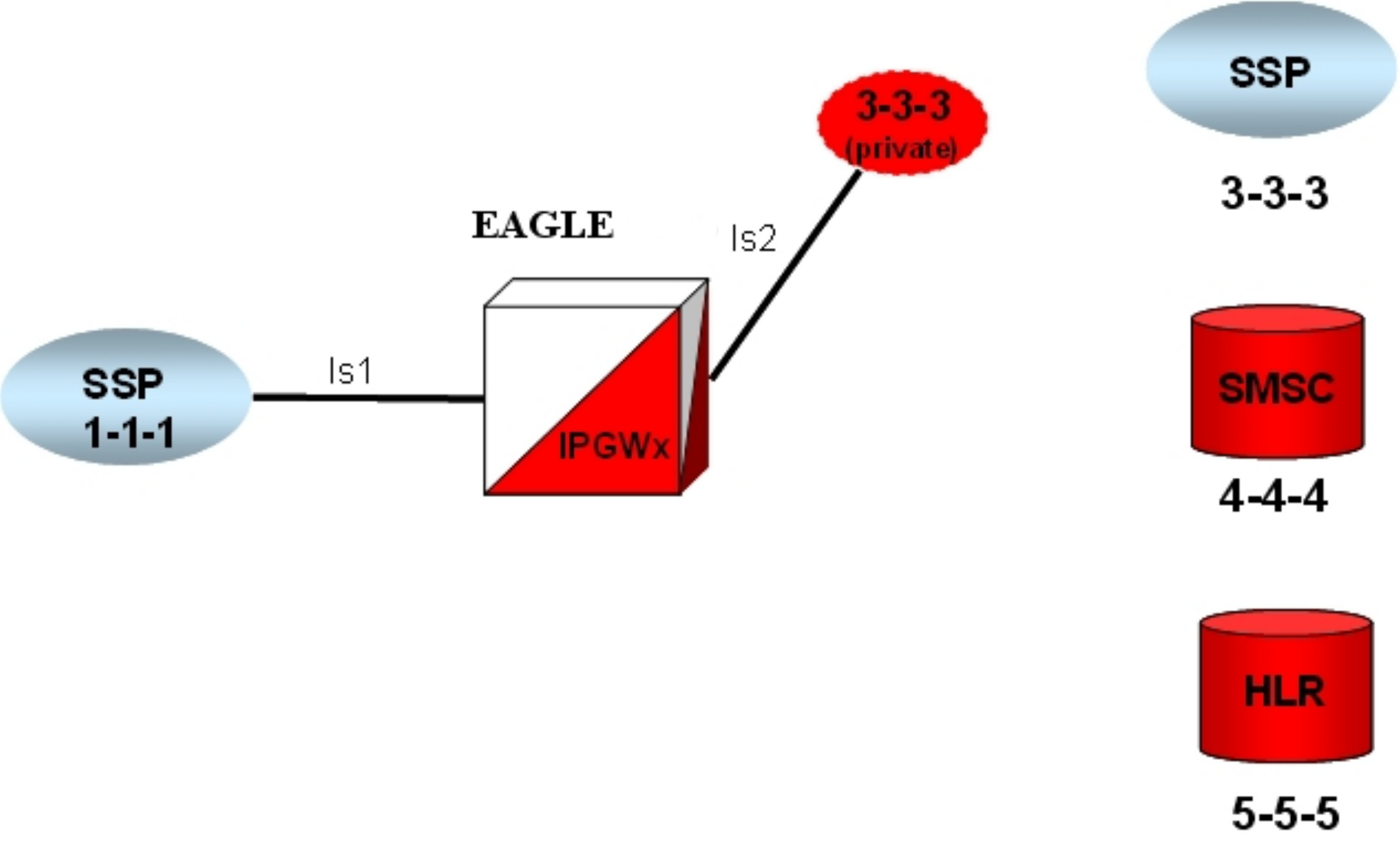
- Enter route (
ent-rte).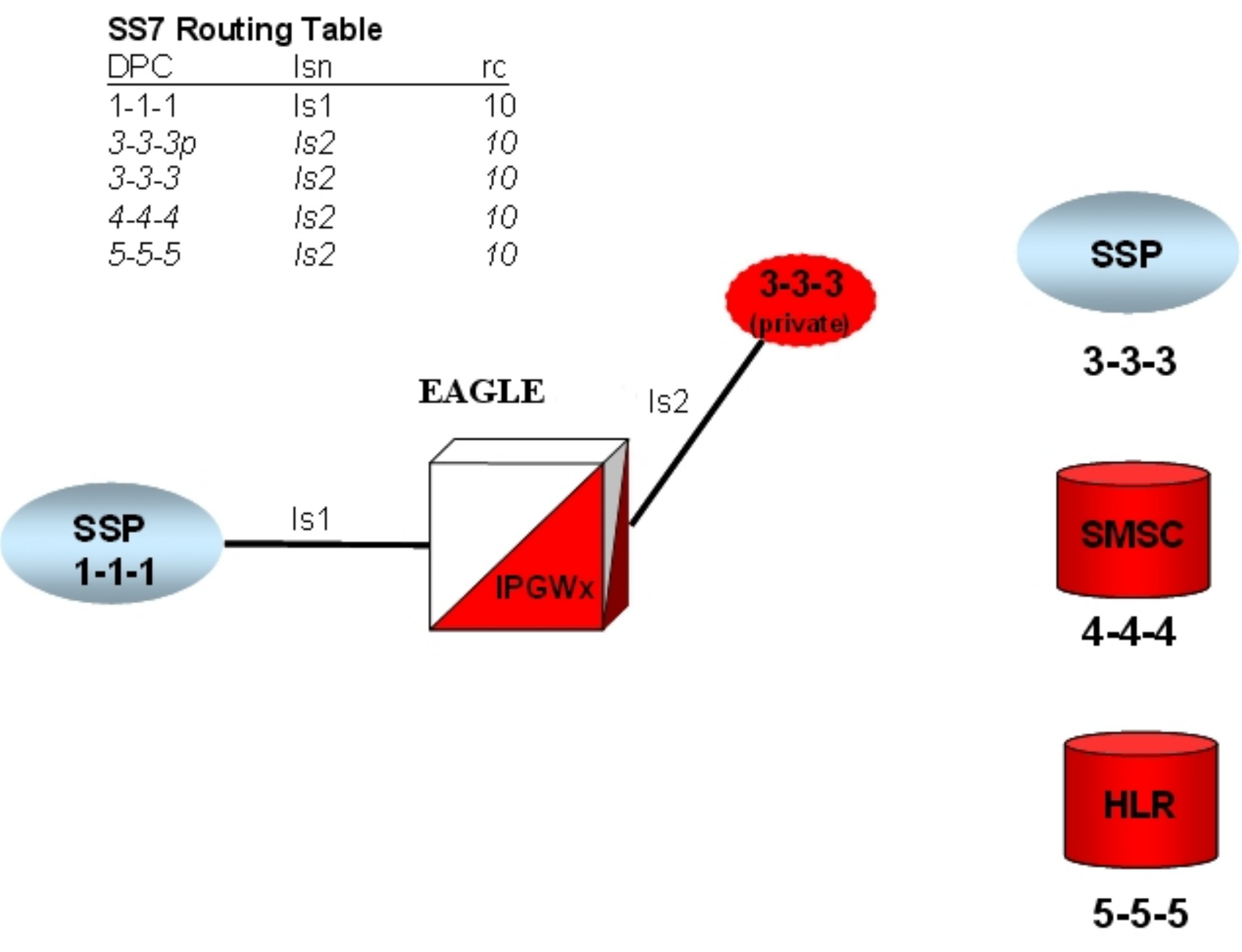
- Define the IP settings for the Ethernet port (
chg-ip-lnk).Enter an Application Server Process and bind an SCTP association with it (ent-assoc)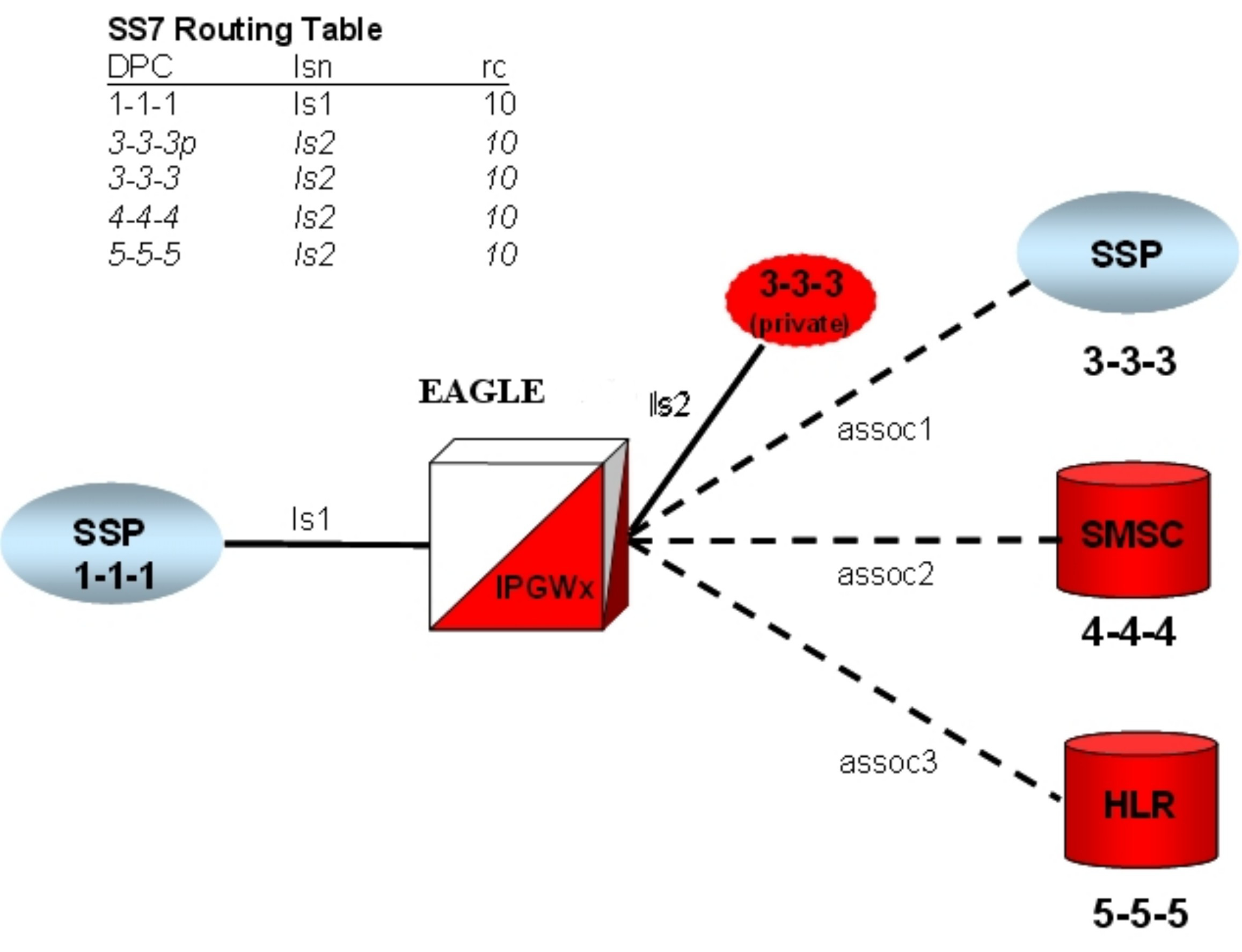
Multihomed end points are SCTP associations configured with both the LHOST and ALHOST parameters specified. In this case, the LHOST represents an IP address corresponding to one of the network interfaces (A or B) of the IP application card, while the ALHOST represents an IP address corresponding to the other network interface of the same IP application card.
This command includes the rmin and rmax parameters.
Refine Timers and Parameters
Define RTIMES Association Retransmits
Set the RTIMES parameter such that an association will be marked unavailable after a reasonable amount of time, based on the values of the RMODE, RMIN and RMAX parameters.
For M2PA, this should be just after M2PA T7 expires (default 1.2 sec).
For example, consider a unihomed M2PA link with RMIN set to 100 msec and RMODE is LINEAR:
Time to mark as failed = RMIN * RTIMES 1200 msec = 100 msec * 12
As long as RTIMES = 12, the association will fail at about the same time MTP3 starts changeover procedures (12 is the maximum for RTIMES).
In this case, decrease M2PA T7 slightly using the chg-m2pa-tset command to guarantee that it will expire before the association is taken down.
For M3UA connections, make this a reasonable amount of time for the network, remembering that multihomed associations could be taken down after only RTIMES/2 retransmits.
Define RTO Parameter
Use the ping-result average RTT measurement for calculation of RMIN.
RMIN should be set to whichever is greater of 1.2 * (Avg. RTT) or (Avg. RTT) + 10 ms.
If errors are greater than 1 per 250,000, then investigate to determine if this can be improved in the network.
RMAX can be set to the worst recorded RTT and further tuned after the association has been established and assocrtt measured.
Define RTXTHR Parameter
:rtxthr –The retransmission threshold for the association. The RTXTHR parameter value indicates the number of packet re-transmissions that can occur on the association (per monitoring time period of 2 seconds). Alarm "IP Connection Excess Retransmits" (UAM 536) will be raised if the number of packets re-transmitted is greater than the configured RTXTHR parameter value, during 5 such consecutive monitoring periods. Once alarm is raised, it may require up to 12 consecutive monitoring periods with the number of re-transmissions < RTXTHR to clear the alarm. The design allows the alarm to come on at low error rates, and not come for occasional errors.
The value of this parameter is 0 to 65,535. The value of this parameter is shown in the RTXTHR field of the rtrv-assoc:aname=<association name> output. The rtxthr parameter value can be changed if the open parameter value is either "yes" or "no". It is possible to configure the RTXTHR so that UAM 536 alarms if the error rate on association is above the recommended maximum packet loss of 0.025%. If the error rate is more than 0.025%, investigate to determine if this can be improved in the network.
Measure Jitter
Measure jitter using ping samples taken from the network. Ideally, a relatively small subset of the samples deviate from the overall Average RTT for the network. The SCTP RMIN parameter value should be adjusted during deployment such that RMIN is approximately equal to 1.2 * Average RTT time in the network. RTT in the network should not exceed 120 ms for E5-ENET or E5-ENET-B cards, or 50 ms for E5-ENET-B cards running the IPSG application when the E5-ENET-B IPSG High Throughput feature is turned on.
System Verification
- Verify Network Connectivity
- Verify IPLIMx configuration or Verify IPGWx configuration, as appropriate.