Creating an Environment
Use the Create Environment page (ECL_ENV_ADD_SCF) to create a new environment.
Important! Before creating an environment in OCI, ensure that the template is updated with OCI-specific Infrastructure Settings such as region, compartment, VCN and subnet settings.
When you use the existing DB system during PUM provisioning, you must ensure that the database versions in the DB system and DPK are the same and that the same DB administrator password that was provided while creating the DB system is used.
Note: Deploying a PeopleSoft Update Image requires a Microsoft Windows platform image that is updated with the latest Windows updates and patches. If the Windows image is not on the latest updates and patches the provisioning of PeopleSoft Client will fail. Refer to the Cloud Manager installation tutorials on Oracle Help Center https://docs.oracle.com/en/applications/peoplesoft/cloud-manager/index.html.
Navigation:
Click the Create Environment button on the Environments landing page.
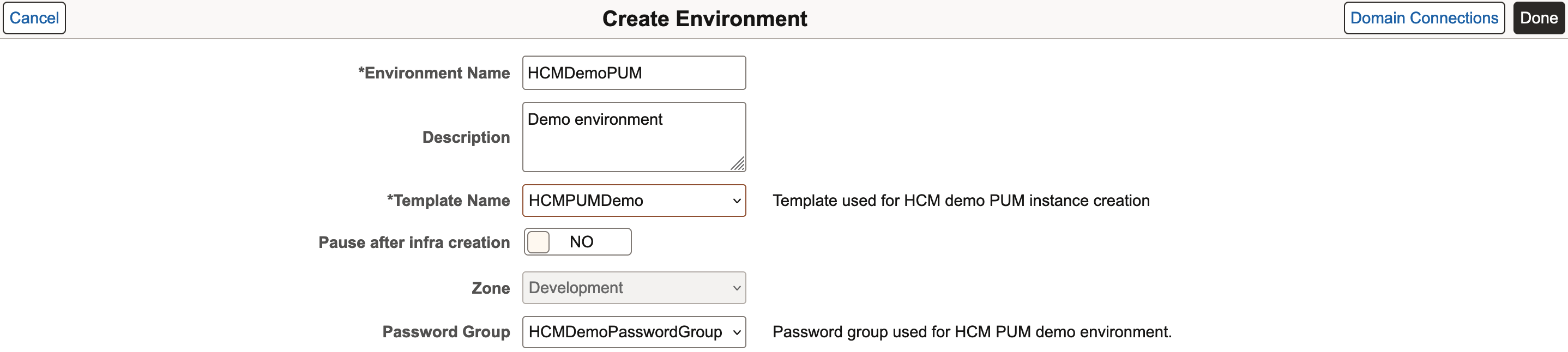
This example illustrates the fields and controls on the Create Environment page. You can find definitions for the fields and controls later on this page.
|
Field or Control |
Description |
|---|---|
|
Environment Name |
Name of the environment that you want to create. It is a required field. Note: Length of environment name must not exceed 20 characters in OCI. |
|
Description |
Description for the environment that you want to create. |
|
Template Name |
Select a template and the zone. On selecting the template, zone options are automatically displayed. It is a required field. For details on templates, see the Creating a Template section under Environments Page. |
|
Pause after infra creation |
Select Yes for the environment provisioning to pause after completion of the Infrastructure task. This provides the user the opportunity to do additional setup, actions, or operations on the newly created environment outside of Cloud Manager before proceeding with the PeopleSoft deployment. Note: When you are ready to proceed to the PeopleSoft deployment, select Deploy from the related actions menu for the environment. Select No (default) to continue provisioning the environment when the infrastructure layer is complete. |
|
Zone |
Select the zone for the environment. If only one zone was defined on the environment template used for this environment, it will be displayed as read-only. |
|
Password Group |
Select the password group that contains the passwords that are already created as secret OCIDs in OCI Vault. The credentials are automatically filled, once you select a password group. |
|
Domain Connections |
Click the button to configure connections between application server domains and web server domains using Domain Connections page. |
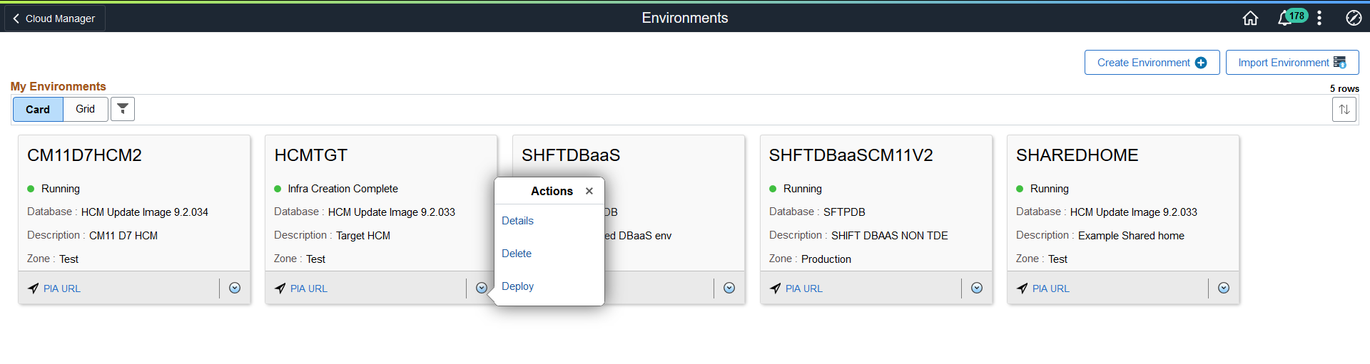
This example illustrates the actions on the Environments page after Infrastructure creation is complete.
After creating topology and template, you can create an environment.
Important! Before creating an environment in OCI, ensure that the template is updated with OCI-specific Infrastructure Settings such as region, primary availability domain, default compartment, default VCN, network settings, and network security group.
To create an environment:
Enter the required environment attributes.
Note: Region and Availability Domains, Network Settings and Network Security sections are read-only.
You can add multiple web server, application server and process scheduler server domains with custom configurations for nodes in the Domain Settings section.
This example illustrates the fields and controls in the Domain Settings section of the Create Environment page.
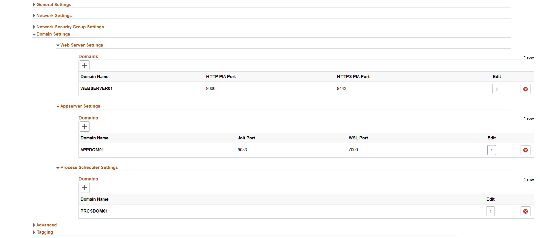
The grid-like structure enables you to customize attribute values at each domain level.
Click > in the Edit column in Web Server Settings section to edit the web server domain configurations.
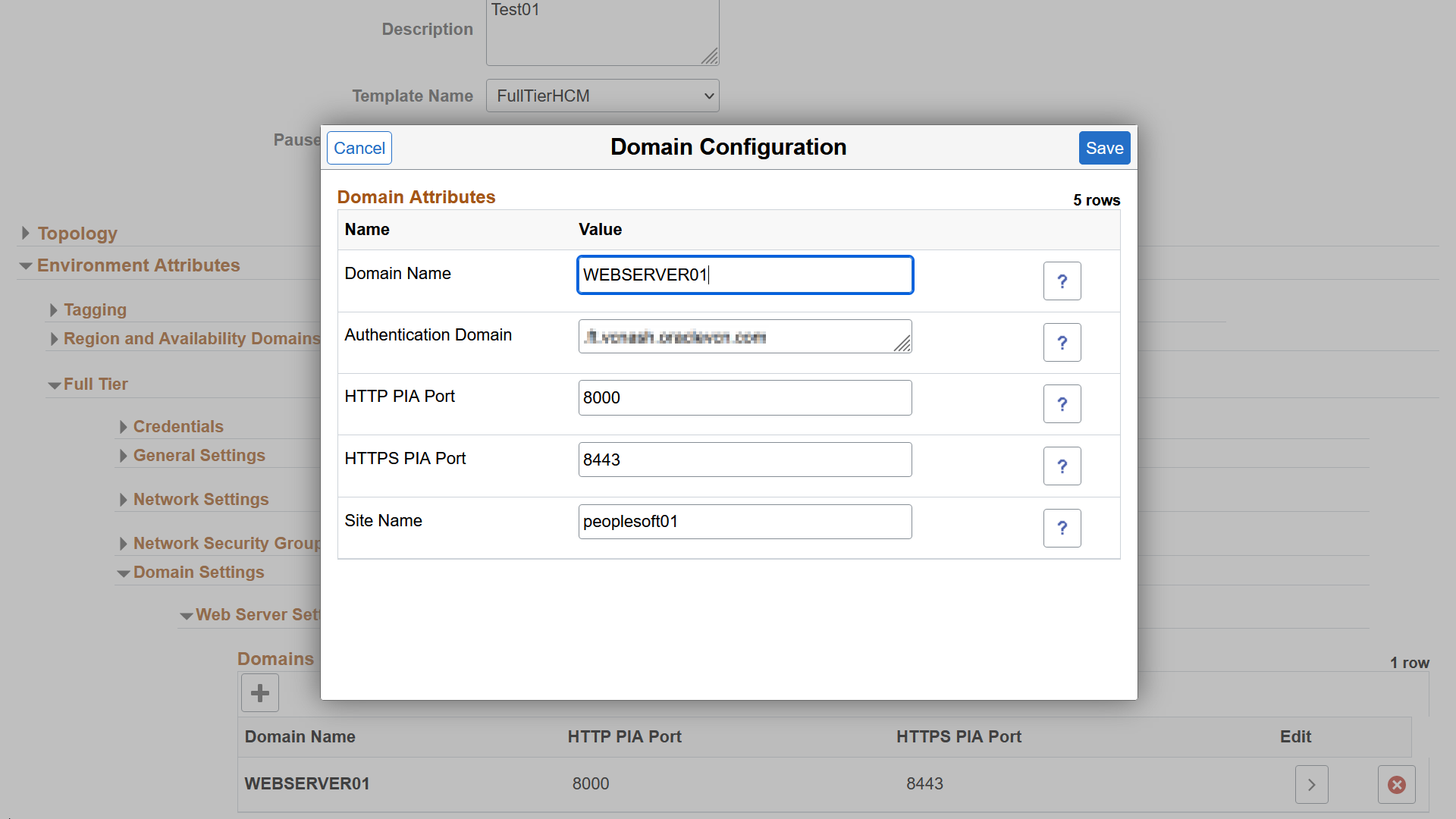
This example illustrates the fields and controls in the Web Server Domain Configuration. You can find definitions for the fields and controls later on this page.
Field or Control
Description
Domain Name
Enter a custom name for web server domain.
Authentication Domain
The domain in which the portal is running and across which the single sign-on authentication token is valid.
Note: The PIA URL must be modified appropriately to access the environment if you have entered a custom authentication token domain value.
HTTP PIA Port
HTTP port for the web server domain.
HTTPS PIA Port
HTTPS port for the web server domain.
Site Name
Name of the site to be created with web server domain.
Click > in the Edit column in App Server Settings section to edit the app server domain configurations.
This example illustrates the fields and controls in the App Server Domain Configuration. You can find definitions for the fields and controls later on this page.
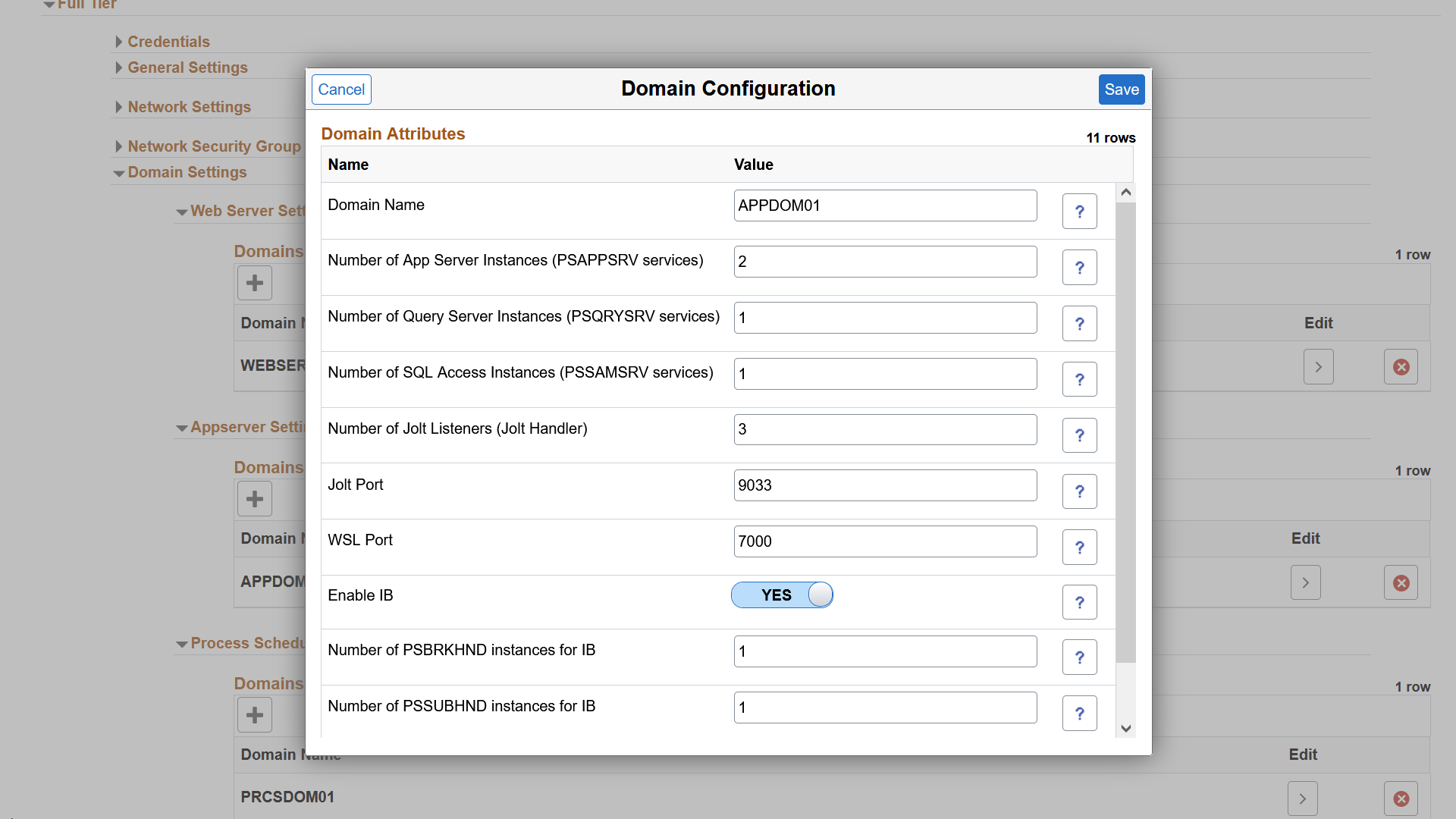
Field or Control
Description
Domain Name
Enter a custom name for application server domain.
Number of App Server Instances(PSAPPSRV services)
Number of PSAPPSRV instances required.
Number of Query Server Instances(PSQRYSRV services)
Number of PSQRYSRV instances required.
Number of SQL Access App Server(PSSAMSRV services)
Number of PSSAMSRV instances required.
Number of Jolt Listeners (Jolt Handler)
Number of Jolt Listener per Domain.
Jolt Port
Jolt port for the app domain.
WSL Port
WSL port for the app domain.
Enable IB
Select Yes to enable IB in the App Domain.
Number of PSBRKHND instances for IB
Number of PSBRKHND instances for IB.
Number of PSSUBHND instances for IB
Number of PSSUBHND instances for IB.
Number of PSPUBHND instances for IB
Number of PSPUBHND instances for IB.
Click > in the Edit column in Process Scheduler Server Settings section to edit the process scheduler server domain configurations.
This example illustrates the fields and controls in the Process Scheduler Server Domain Configuration. You can find definitions for the fields and controls later on this page.
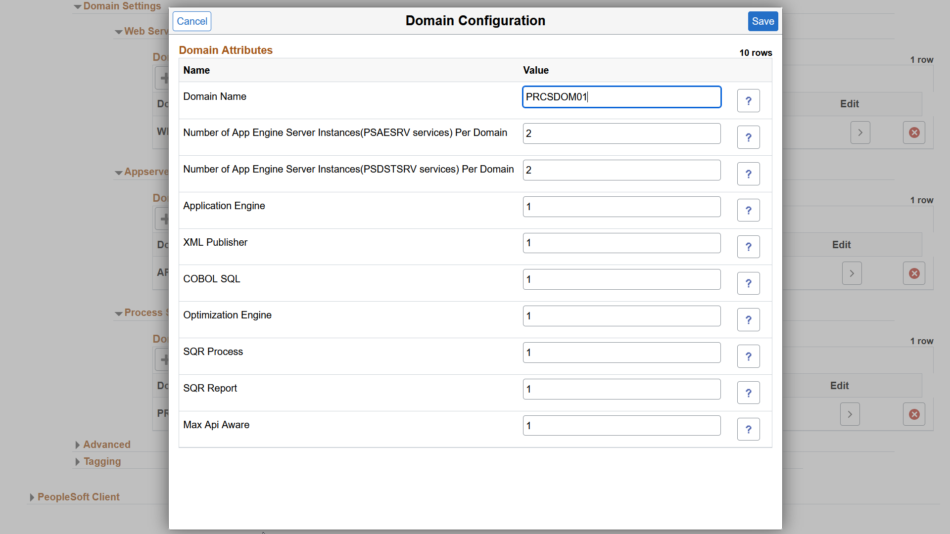
Field or Control
Description
Domain Name
Accept the default or enter a custom domain name.
Number of App Engine Server Instances(PSAESRV services) Per Domain
Number of application engines required.
Number of App Engine Server Instances(PSDSTSRV services) Per Domain
Number of application servers required.
Application Engine
Number of application engine processes.
XML Publisher
Number of XML publishers.
COBOL SQL
Number of COBOL SQL processes.
Optimization Engine
Number of optimization engines.
SQR Process
Number of SQR processes.
SQR Report
Number of SQR reports.
Max Api Aware
Number of Max Api Aware. Indicates the total number of tasks that a Process Scheduler can initiate concurrently.
Click Save to save the changes.
Click + on the respective domain grid to add a new domain and click X to delete a domain.
Click Done to start environment provisioning.
Note: The system validates available resources before starting the provisioning process. See Validating Resources.
Select the Provision Task Status link to view the progress of the environment creation. See Viewing Provision Task Status. If a failure occurs, you can retry and resume the operation. See Retrying and Resuming Provisioning.
Alternately, you can override the default topology and environment attributes while environment provisioning.
The default database operator id for each PeopleSoft PUM instance is listed below:
For HCM, default database operator id is PS.
For FSCM, default database operator id is VP1.
For CRM, default database operator id is VP1.
For ELM, default database operator id is PS.
For IH, default database operator id is VP1.
For CS, default database operator id is PS.
Configure connections between application server domains and web server domains using Domain Connections page.
To select the required configuration for an environment or node:
Click Domain Connections on the Create Environment page.
Select the application server domains to be connected with each web server node. Multiple Integration Broker-enabled application server domains can be connected to web servers.
This example illustrates the fields and controls on the Domain Connections page.
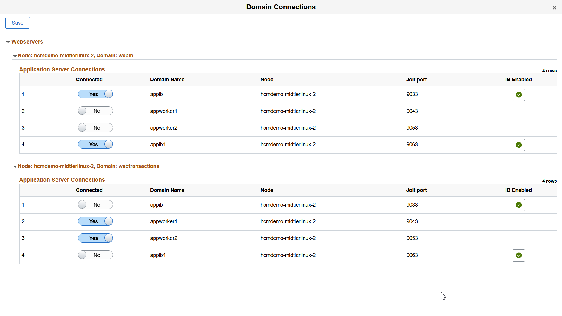
Field or Control
Description
Connected
Select Yes to choose the application server domains to be connected with each web server node.
Domain Name
Displays the domain associated with the application server.
Node
Displays the node containing application server domain.
Jolt port
Displays the Jolt port for the application server domain.
IB Enabled
Flagged rows represent the application server domains that are enabled for Integration Broker.
Click Save. The node is provisioned with the selected configuration.
Note: At least one application server domain must be connected to each web server.
If the template contains multiple topologies, you can override default topology and attributes.
To override the topology:
Select Yes in Override Topology field.
This example illustrates the fields and controls in the Topology section of the Create Environment page.
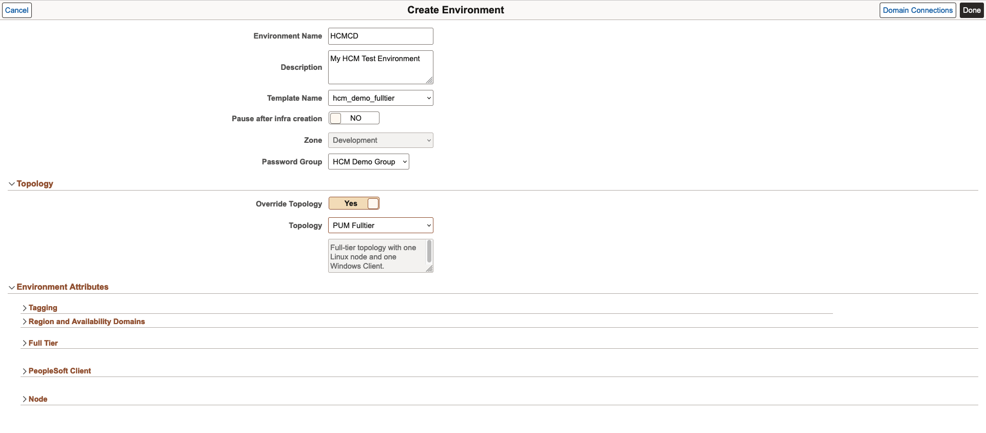
Select an appropriate Topology. Corresponding description is displayed in the below text area.
Input the required environment attributes. The different attributes are:
Full Tier: Full Tier is the VM where application server domain, process scheduler domain, and the web server domain are installed.
Middle Tier: Middle Tier Node can be created in either Linux or Windows. The Linux Middle Tier is the VM where application server domain, process scheduler domain, and the web server domain are installed. The Windows Middle Tier is the VM where Windows process scheduler is installed.
Database Tier: Database tier is the VM where the database (non-DbaaS) is installed for the new PSFT system.
PeopleSoft Client: PeopleSoft Client is the VM where PeopleTools client (for example, PeopleSoft Application Designer, or pside) and Change Assistant are pre-installed.
Database as a Service: PeopleSoft database is deployed on DBaaS.
Search Stack: Search Stack Tier is the VM where Elasticsearch server and Kibana (or OpenSearch and OpenSearch Dashboards) are installed.
Enter the PeopleSoft Client credentials and other required attributes.
Note: In case of OCI, the password for the PeopleSoft Client instance should meet the password complexity as per the OCI requirement.
Some custom attributes are displayed based on the selected topology nodes. If you select a Search Stack node, then you need to provide a couple of input parameters and passwords. Password must be at least 9 characters long and contain a numeric and one uppercase letter. Special characters are not accepted.Click Done to start environment provisioning.
Note: The system validates available resources before starting the provisioning process. See Validating Resources.
Select the Provision Task Status link to view the progress of the environment creation. See Viewing Provision Task Status. If a failure occurs, you can retry and resume the operation. See Retrying and Resuming Provisioning.
Note: Ensure to tune the servers, database, and PeopleSoft system for optimum performance once the deployment is completed.
If you selected to use the Linux Image from Marketplace and this is the first time you are provisioning an environment in a specific compartment, a License agreement will be displayed and must be accepted to continue.
Each compartment needs to accept the license if it has not already been accepted for that compartment.
Multiple middle tiers in an environment can share PS_HOME, PS_APP_HOME and PS_CUST_HOME.
Note: Shared File System is only supported for Linux middle Tier. Windows middle tier is not supported.
User must first create a new File Storage Service (FSS) in the OCI. It is recommended that this new FSS be in the same availability domain (AD) where the middle tier of the environment is provisioned.
Important! You should not use the File Storage System that you created for the Cloud Manager repository as the file system for a middle tier node in a provisioned environment.
When creating the FSS, keep the following in mind:
All VMs in the subnet should have read/write access.
See the tutorial Plan the Virtual Cloud Network for PeopleSoft Cloud Manager (Optional).
File storage mount target (TCP ports 111, 2048, 2049, 2050; UDP ports 111 and 2048) is specific to FSS ports, this has to be opened in Linux MT machines.
FSS export path requires full read/write access.
Network access (ports and security rules) must be configured to Mount Targets from the middle tier nodes.
Mount Target must be a minimum of 1024 GB.
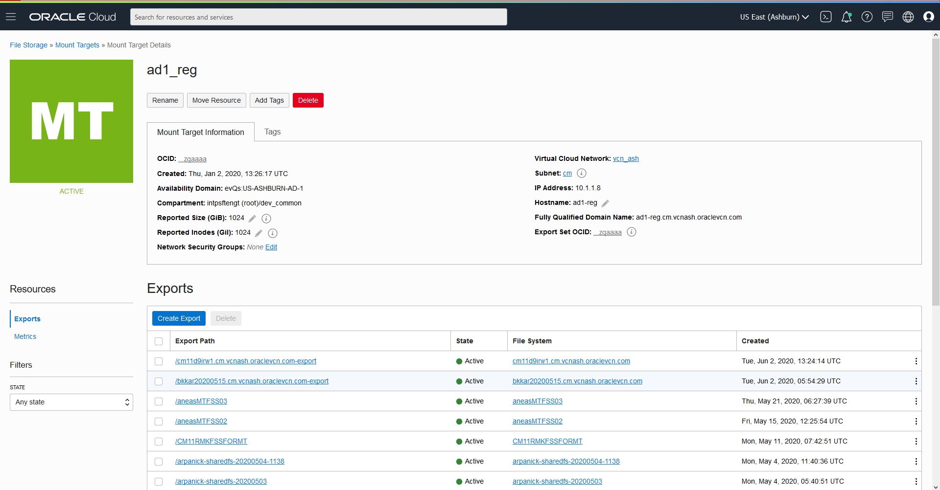
This example illustrates the fields and controls on the Mount Target Details page.
Once the environment is running, user can update the FSS export path read/write permission to Linux Middle Tier.
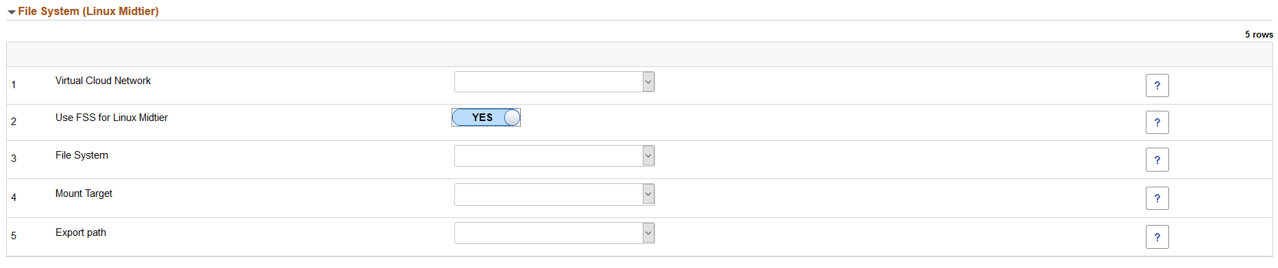
This example illustrates the fields and controls on the File System (Linux Midtier) section. You can find definitions for the fields and controls later on this page.
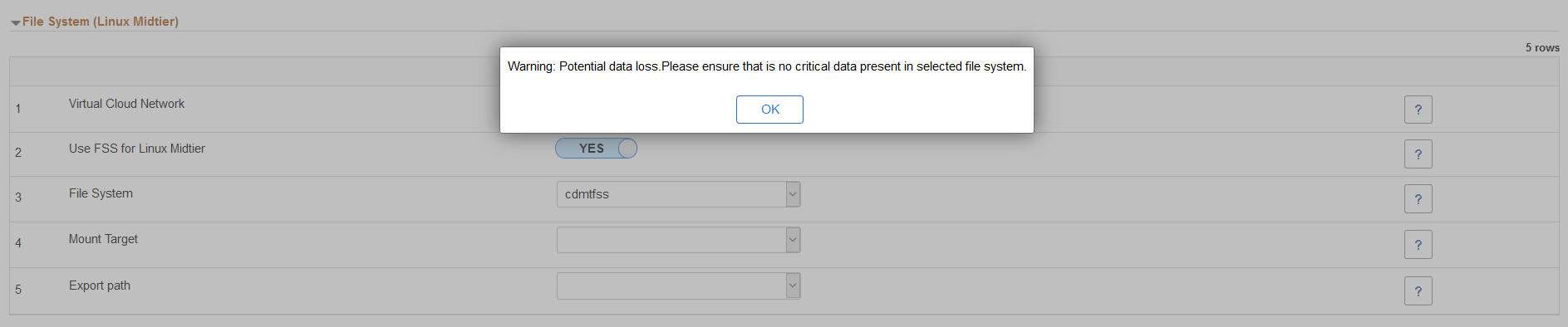
This example illustrates the File System warning message.
|
Field or Control |
Description |
|---|---|
|
Virtual Cloud Network |
Select the Virtual Cloud Network. |
|
Use FSS for Linux Midtier |
Select Yes to use FSS for Linux Midtier |
|
File System |
Select the File System from the available file systems in OCI. Note: When you tab off the field, a warning is displayed for potential loss of data. The file system should not contain any critical data. |
|
Mount Target |
Select the Mount Target from the drop down list. |
|
Export path |
Select the Export path from the drop down list. |
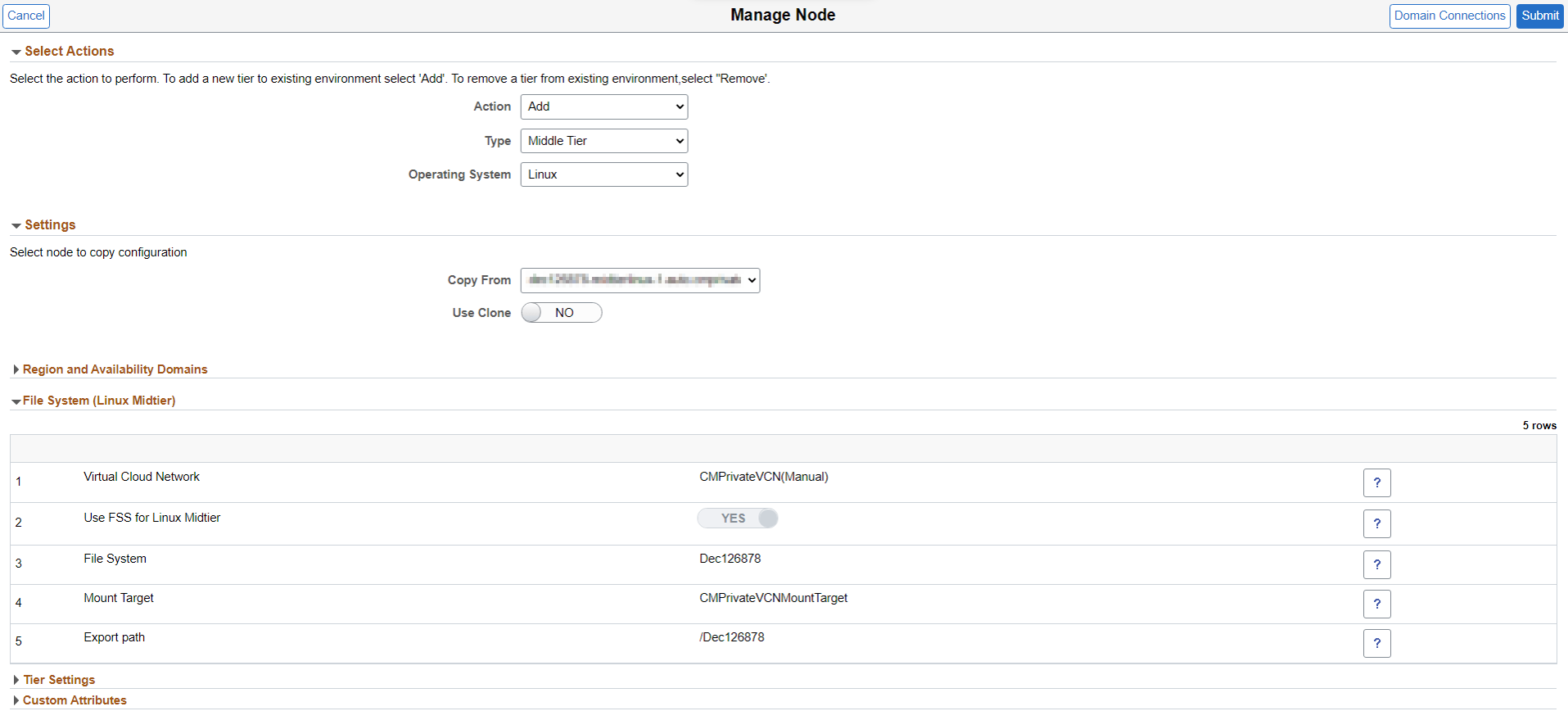
Adding a New Middle Tier
After creating an environment that includes a shared file system, use the Manage Node action to add a new middle tier that will share the same PS_HOME, PS_APP_HOME and PS_CUST_HOME.
See Managing Nodes
This example illustrates the fields and controls on the Manage Node page - Add Middle Tier with FSS.
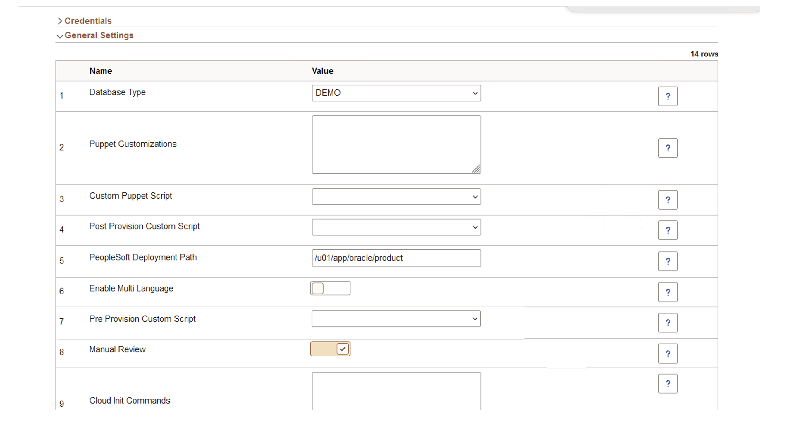
When you create an environment, you have the global option to enable all the manual reviews selected in the chosen template, or alternatively enable or disable all the manual review steps in the template.
If the status of an action step is "Manual Review", the Retry action is enabled in all the activities and action steps in that task. When you select Retry for any activity or action step, all the activities or action steps after that are run again.
By default, the option to go with the selection made during template creation is enabled. You can enable or disable all manual review steps using this field.
This example illustrates the fields and controls on the Create Environment page with Manual Review.

|
Field or Control |
Description |
|---|---|
|
Default to Template |
Select this option to use the Manual Review values in chosen environment template as the default value in environment provisioning. You can override this selection in individual instances. |
|
Disable All |
Select this option to disable Manual Review in all the instances. |
|
Enable All |
Select this option to enable Manual Review in all the instances. |
You can modify the selection for individual instances in General Settings. By default, the selection for Manual Review is disabled.
This example illustrates the fields and controls on the General Settings tab.
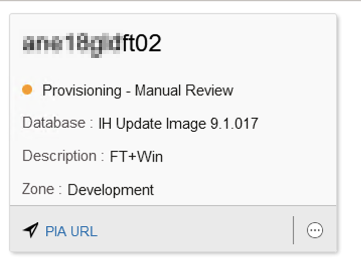
The environment tile shows the status as “Provisioning – Manual Review” when the manual review is in progress.
Manual reviewing of steps is currently available only during provisioning use case and is not applicable for shift provisioning and scaling up use cases. Manual Review is enabled for following environment types:
Full Tier
Middle Tier
Database Tier
Database Systems
Windows MT
Note: The Manual Review step is included for reviewing the processing of Customer DPK. This capability will be extended to other actions and activities during future releases of Cloud Manager.