
This part describes network requirements and functionality for systems with a network architecture based on a physical high-speed Ethernet fabric.
Oracle Private Cloud at Customer relies on different physical and logical networks to provide secure and reliable network connectivity for different application and management functions. This section outlines the minimum network requirements to install an Oracle Private Cloud at Customer system.
Infrastructure Management Network
All infrastructure components inside the base rack are physically connected to this Gigabit Ethernet network, which uses the
192.168.4.0/24subnet. A single uplink connects it to an Oracle-managed switch, which integrates the management interface of the Oracle Advanced Support Gateway. With a second network interface, the support gateway connects to the data center network, enabling Oracle to access the infrastructure management network remotely. No customer or external access to this network is permitted.Data Network
The appliance data connectivity is built on redundant Cisco Nexus 9336C-FX2 Switches in a leaf-spine design. In this two-layer design, the leaf switches interconnect the rack hardware components, while the spine switches form the backbone of the network and perform routing tasks.
The Cisco Nexus 9336C-FX2 Switch offers a maximum throughput of 100Gbit per port. The spine switches use 5 interlinks (500Gbit); the leaf switches use 2 interlinks (200Gbit) and 2x2 crosslinks to the spines. Each compute node is connected to both leaf switches in the rack, through the
bond1interface that consists of two 100Gbit Ethernet ports in link aggregation mode. The two storage controllers are connected to the spine switches using 4x40Gbit connections.For external connectivity, 5 ports are reserved on each spine switch. Four ports are available for custom network configurations; one port is required for the default uplink. This default external uplink requires that port 5 on both spine switches is split using a QSFP+-to-SFP+ four way splitter or breakout cable. Two of those four 10GbE SFP+ breakout ports per spine switch, ports 5/1 and 5/2, must be connected to a pair of next-level data center switches, also called top-of-rack or ToR switches.
Software Defined Networks
While the physical data network described above allows the data packets to be transferred, the true connectivity is implemented through Software Defined Networking (SDN), using VxLAN encapsulation and VLAN tagging. Traffic can be internal between resources within the appliance environment, or external to network storage, applications, or other resources in the data center or on the internet. SDN maintains the traffic separation of hard-wired connections, and adds better performance and dynamic (re-)allocation.
From the perspective of the customer network, the use of VxLANs in Oracle Private Cloud at Customer is transparent: encapsulation and de-encapsulation take place internally, without modifying inbound or outbound data packets. In other words, this design extends customer networking, tagged or untagged, into the virtualized environment hosted by the appliance.
During the system initialization process, several essential default networks are configured:
The Internal Storage Network is a redundant 40Gbit Ethernet connection from the spine switches to the ZFS storage appliance. All four storage controller interfaces are bonded using LACP into one datalink. Management and compute nodes can reach the internal storage over the
192.168.40.0/21subnet on VLAN 3093. This network also fulfills the heartbeat function for the clustered Oracle VM server pool.The Internal Management Network provides connectivity between the management nodes and compute nodes in the subnet
192.168.32.0/21on VLAN 3092. It is used for all network traffic inherent to Oracle VM Manager, Oracle VM Server and the Oracle VM Agents.The Internal Underlay Network provides the infrastructure layer for data traffic between compute nodes. It uses the subnet
192.168.64.0/21on VLAN 3091. On top of the internal underlay network, internal VxLAN overlay networks are built to enable virtual machine connectivity where only internal access is required.The External Underlay Network provides the infrastructure layer for data traffic between Oracle Private Cloud at Customer and the data center network. It uses the subnet
192.168.72.0/21on VLAN 3090. On top of the external underlay network, VxLAN overlay networks with external access are built to enable public connectivity for the physical nodes and all the virtual machines they host.The default external VxLAN overlay network also provides access to the management nodes from the data center network and allows the management nodes to run a number of system services.
Virtual Machine Networks are VxLAN overlay networks, configured to use the underlay networks, described above, as their infrastructure layer. Two VxLAN networks are configured in advance: the default internal VM network, which supports untagged traffic by default, and the default external network, which supports both tagged and untagged traffic by default. Customers can add VLANs of their choice to the Oracle VM network configuration, and define the subnet(s) appropriate for IP address assignment at the virtual machine level.
Virtual machine networking can be further diversified and segregated by means of custom networks. Custom networks are infrastructure networks, constructed in the same way as the default private and public networks, but using different compute node network interfaces and terminating on different spine switch ports. Whenever public connectivity is required, additional cabling between the spine switches and the next-level data center switches is required. Network customization must be performed by Oracle.
A Virtual Machine Storage Internal Network is created during system configuration, so that shared NFS storage can be presented to virtual machines. The necessary IP addresses are specified by the customer prior to installation.
In addition, Oracle Private Cloud at Customer requires the following data center network services:
DNS Service
As part of the deployment process, you work together with Oracle to determine the host names and IP addresses to be used when deploying Oracle Private Cloud at Customer. The fully qualified domain names (FQDN) and IP addresses of the management nodes must be registered in the data center Domain Name System (DNS).
NTP Service
At least one reliable Network Time Protocol (NTP) server is required and should be accessible on the client network. This role is fulfilled by the Oracle Advanced Support Gateway. The management nodes are configured to synchronize with the NTP server. All other Oracle Private Cloud at Customer components are configured to reference the active management node for clock synchronization.
Every Oracle Private Cloud at Customer rack is shipped with the required network equipment to support the Oracle Private Cloud at Customer rack. Every base rack also contains pre-installed cables for all rack units where additional compute nodes can be installed during a future expansion of the environment. However, customers must supply the transceivers in their switches, as well as the cabling from the data center network to the rack location.
Before the Oracle Private Cloud at Customer system is powered on for the first time, two high-speed Ethernet ports on each spine Cisco Nexus 9336C-FX2 Switch must be connected to the data center public Ethernet network. These are ports 5/1 and 5/2, which are configured at 10Gbit and intended as the default connection for appliance management and setup. This configuration is locked and must remain at 10Gbit; it requires breakout cables with a QSFP+ transceiver on the spine switch end and four SFP+ transceivers on the other end.
Figure 4.1 shows the location of the two 10 GbE breakout ports on the spine switches, which must be connected to the data center network.
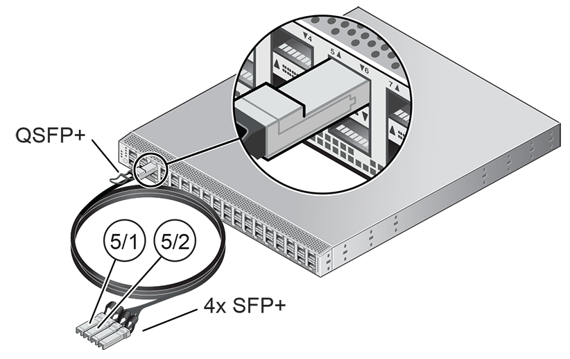
It is critical that both spine switches have two 10GbE connections each to a pair of next-level data center switches, or top-of-rack (ToR) switches. This configuration with four cable connections provides redundancy and load splitting at the level of the spine switches, the 10GbE ports and the data center switches. This outbound cabling from the pair of spine Cisco Nexus 9336C-FX2 Switches should be crossed: each spine switch must be connected to two (ToR) next-level data center switches. The cabling pattern plays a key role in the continuation of service during failover scenarios.
To provide additional bandwidth to the environment hosted on Oracle Private Cloud at Customer, additional custom networks can be configured. Please contact your Oracle representative for more information.
When configuring the data center switches to accept incoming Oracle Private Cloud at Customer uplinks – the default uplinks as well as any custom uplinks – take these notes into account.
All uplinks, default and customer, are configured to use link aggregation (LACP). All four switch ports included in an uplink configuration – two per spine switch – must belong to the same link aggregation group (LAG), also known as port channel. The switch ports on the data center side of the uplinks must be configured accordingly.
The data center switch ports to which the Oracle Private Cloud at Customer uplinks are connected, must be set to trunk mode.
The spine switches operate with the Virtual Port Channel (vPC) feature enabled. Therefore, the standard Spanning Tree Protocol (STP) is not supported in the data center network ports connected to the Oracle Private Cloud at Customer. If spanning tree protocol is required on the switch ports connected to Oracle Private Cloud at Customer, you must use the Multiple Spanning Tree Protocol (MSTP) or a compatible protocol.
Auto-negotiation is not available for uplink ports. Transfer speed must be specified on the customer switches' end. For the default uplink ports, this is 10Gbit/s.
Example
Below is an example of a custom uplink configuration for your reference.
In this example, port 3 on both spine switches is split into 4x 25Gbit. Ports 3:1 and 3:2 are cross-cabled to a pair of ToR switches. Like the internal spine switches of the Oracle Private Cloud at Customer, the two ToR switches have the virtual port channel (vPC) feature enabled, allowing ports from both switches to operate within the same port channel.
These are the key configuration parameters:
The vPC feature must be enabled on both ToR switches: vpc domain 1.
Ports 49 and 50 on both ToR switches must belong to port channel 200.
Port channel 200 on both ToR switches must belong to virtual port channel 200.
Port channel parameters, such as MTU, speed and spanning tree filter, must be identical on both ToR switches.
All port channel and switch port interfaces are set to trunk mode.
ToR switch A configuration:
feature lacp
feature vpc
vpc domain 1
    peer-switch
    role priority 1
    peer-keepalive destination <ToR-B_IP> source <ToR-A_IP>
    peer-gateway
    layer3 peer-router
    ip arp synchronize

interface port-channel 200
    description "Uplink PCA 3:1 3:2 port channel"
    switchport mode trunk
    switchport trunk allowed vlan 1-4094     ### optional, typical default setting
    switchport trunk native vlan 500         ### optional, for data center vlan
    speed 25000
    mtu 9216
    vpc 200

interface Ethernet 1/49
    description "PCA spine 1 Port 3:1"
    switchport mode trunk
    switchport trunk allowed vlan 1-4094     ### optional, typical default setting
    switchport trunk native vlan 500         ### optional, for data center vlan
    speed 25000
    mtu 9216
    channel-group 200 mode active

interface Ethernet 1/50
    description "PCA spine 2 Port 3:1"
    switchport mode trunk
    switchport trunk allowed vlan 1-4094     ### optional, typical default setting
    switchport trunk native vlan 500         ### optional, for data center vlan
    speed 25000
    mtu 9216
    channel-group 200 mode active
ToR switch B configuration:
feature lacp
feature vpc
vpc domain 1
    peer-switch
    role priority 2
    peer-keepalive destination <ToR-A_IP> source <ToR-B_IP>
    peer-gateway
    layer3 peer-router
    ip arp synchronize

interface port-channel 200
    description "Uplink PCA 3:1 3:2 port channel"
    switchport mode trunk
    switchport trunk allowed vlan 1-4094     ### optional, typical default setting
    switchport trunk native vlan 500         ### optional, for data center vlan
    speed 25000
    mtu 9216
    vpc 200

interface Ethernet 1/49
    description "PCA spine 1 Port 3:2"
    switchport mode trunk
    switchport trunk allowed vlan 1-4094     ### optional, typical default setting
    switchport trunk native vlan 500         ### optional, for data center vlan
    speed 25000
    mtu 9216
    channel-group 200 mode active

interface Ethernet 1/50
    description "PCA spine 2 Port 3:2"
    switchport mode trunk
    switchport trunk allowed vlan 1-4094     ### optional, typical default setting
    switchport trunk native vlan 500         ### optional, for data center vlan
    speed 25000
    mtu 9216
channel-group 200 mode activeDuring the initial software configuration of Oracle Private Cloud at Customer, the network settings of the management nodes must be reconfigured. For this purpose, you should reserve three IP addresses in the public (data center) network: one for each management node, and one to be used as virtual IP address shared by both management nodes. If the data center network traffic is tagged, make sure that the VLAN ID is also provided as part of the configuration.
Oracle Private Cloud at Customer also requires a large number of preassigned private IP addresses. To avoid network interference and conflicts, you must ensure that the data center network does not overlap with any of the infrastructure subnets of the Oracle Private Cloud at Customer default configuration. These are the subnets and VLANs you should keep clear:
Subnets:
192.168.4.0/24 – internal machine administration network: connects ILOMs and physical hosts
192.168.32.0/21 – internal management network: traffic between management and compute nodes
192.168.64.0/21 – underlay network for east/west traffic within the appliance environment
192.168.72.0/21 – underlay network for north/south traffic, enabling external connectivity
192.168.40.0/21 – storage network: traffic between the servers and the ZFS storage appliance
Each /21 subnet comprises the IP ranges of
eight /24 subnets or over 2000 IP
addresses. For example: 192.168.32.0/21
corresponds with all IP addresses from
192.168.32.1 to
192.168.39.255.
VLANs:
1 – the Cisco default VLAN
3040 – the default service VLAN
3041-3072 – a range of 31 VLANs reserved for customer VM and host networks
3073-3099 – a range reserved for system-level connectivity
NoteVLANs 3090-3093 are already in use for tagged traffic over the
/21subnets listed above.3968-4095 – a range reserved for Cisco internal device allocation