5 Servicing FRUs

Perform tasks for servicing field-replaceable units (FRUs) for the Oracle Database Appliance that require you to power off the system and/or server node.

When servicing FRU components, the server node and/or system must be powered down and the AC power cords disconnected.

Note:

Only authorized Oracle Service personnel can service FRU components.

Servicing Processors (FRU)

Perform tasks described in this section to service processors.

Processors are replaceable components that require you to power off the server before servicing.

Caution:

Ensure that all power is removed from the server before removing or installing a processor. You must disconnect the power cables from the system before performing these procedures.

Caution:

These procedures require that you handle components that are sensitive to electrostatic discharge. This sensitivity can cause the component to fail. To avoid damage, ensure that you follow electrostatic discharge safety measures and antistatic practices. See Electrostatic Discharge Safety.

Note:

On single-processor systems, processor socket 1 (P1) is shipped without a heatsink and with an External Cap. To protect the delicate processor socket pins, do not remove the External Cap that was installed on the motherboard.

Processor Overview

Socket components in the processor assembly have a pin 1 indicator to aid in assembly.
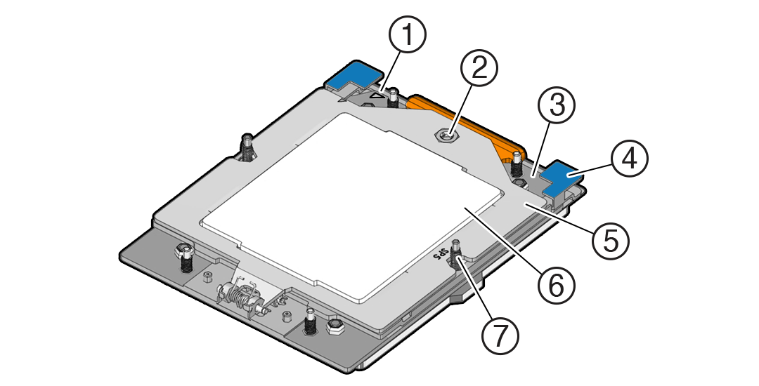

Description of mm-11076_processor-components.png follows
Description of the illustration mm-11076_processor-components.png
Callout Description

1

Pin 1 orientation

2

Force Frame Retention Screw (captive)

3

Rail Frame (socket stiffener frame)

4

Release Tabs (2x)

5

Force Frame (retention frame)

6

Processor Package (carrier frame holding preinstalled processor)

7

Heatsink Attachment Studs (6x)

Identify and Remove a Processor

  • Use ESD gloves (not latex or vinyl), if possible, when handling the processor.

  • Obtain a Torx T20 screwdriver for processor and heatsink removal.

  • Obtain the materials required to remove the old thermal interface material (TIM).

    • Isopropyl alcohol wipes (included with FRU kit)
    • Techwipes or similar low-lint and low-abrasion wipe
    • Isopropyl alcohol (90% or above recommended)

    Caution:

    Failure to remove/replace the old TIM can result in processor overheating.

  • Be careful not to touch the processor socket pins.

    Caution:

    The processor socket pins are very fragile. A light touch can bend the processor socket pins beyond repair.
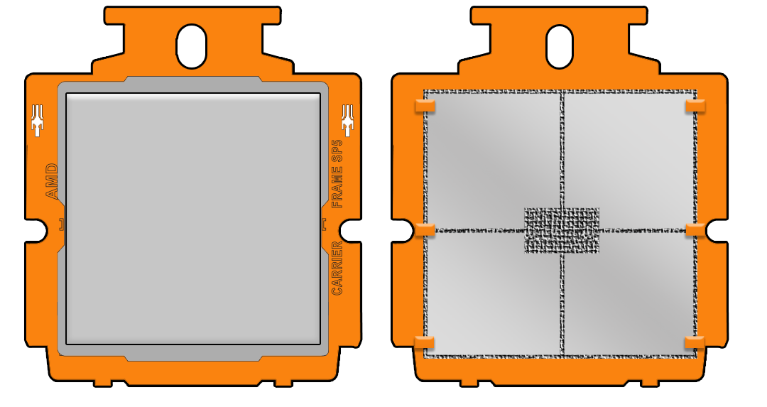
  • Replacement processors come preinstalled on a special carrier to ensure safe handling. Never remove the processor from its carrier.
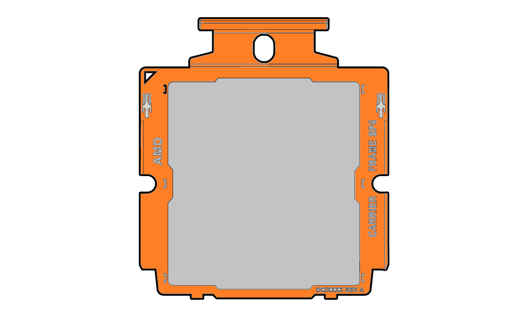
    Description of mm-10729_processor-carrier_2.png follows
    Description of the illustration mm-10729_processor-carrier_2.png
  • On a two processor system, if you remove a processor for replacement do not attempt to operate the system with a single processor as the server might overheat due to improper airflow. A two processor system requires both processors and their heatsinks installed to operate properly.

  1. Prepare the server for service.
    1. Power off the server.
    2. Disconnect the power cords from the power supplies.
    3. Extend the server to the maintenance position.
    4. Attach an antistatic wrist strap to your wrist, and then to a metal area on the chassis.
    5. Remove the server top cover.
    6. Remove the air baffle.
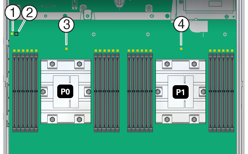
  2. Identify the location of the failed processor by pressing the Fault Remind button on the motherboard.

    The following illustration identifies the location of the Fault Remind button and processor fault LEDs.


    Callout Description

    1

    Fault Remind circuit power LED - green

    2

    Fault Remind button

    3

    Processor 0 fault LED - amber

    4

    Processor 1 fault LED - amber

    When you press the Fault Remind button, the processor fault LED for the failed processor illuminates.

    • If the processor fault LED is off, the processor is operating properly.

    • If the processor fault LED is illuminated (amber), the processor failed and you must replace it.

    Note:

    When you press the Fault Remind button, an LED located next to the Fault Remind button illuminates green, indicating that there is sufficient voltage in the fault remind circuit to illuminate any fault LEDs that were illuminated due to a failure. If this LED fails to illuminate when you press the Fault Remind button, it is likely that the capacitor powering the fault remind circuit lost its charge. This can happen if you press the Fault Remind button for a long time with fault LEDs illuminated, or if power was removed from the server for more than 15 minutes.
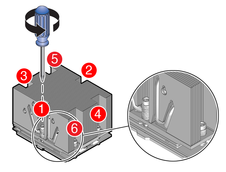
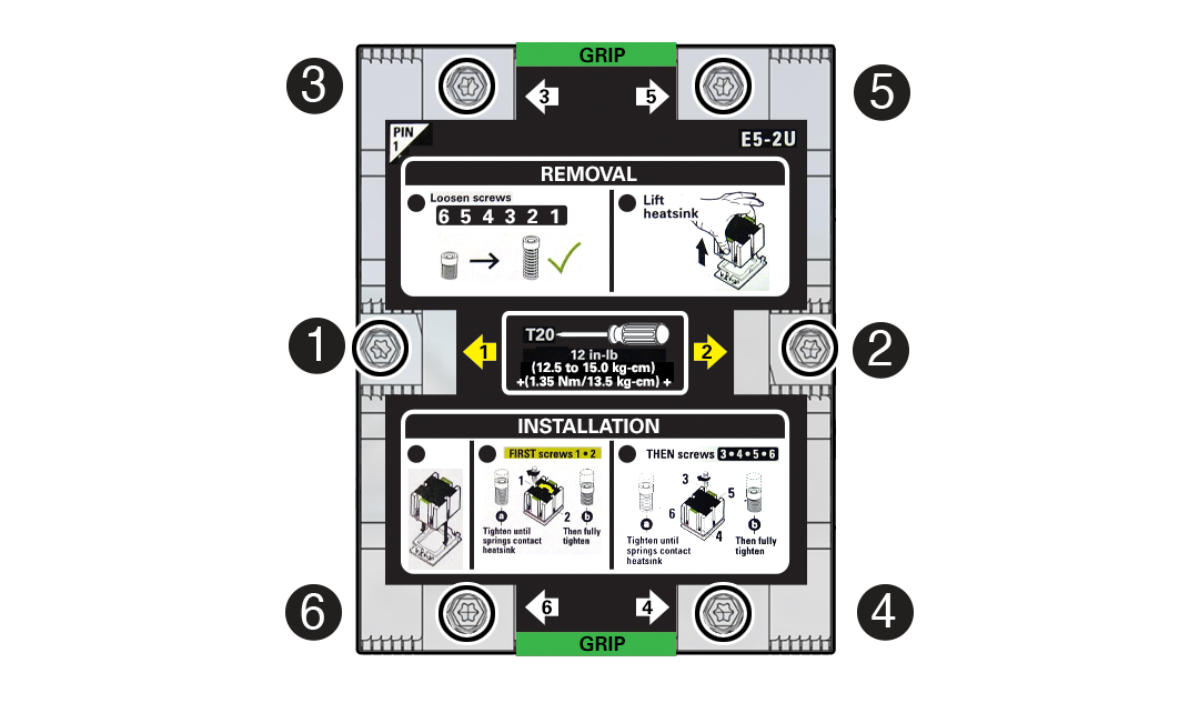
  3. Using a Torx T20 screwdriver, loosen the six captive screws that secure the processor heatsink to the socket.

    Description of aog-256_remove-processor.png follows
    Description of the illustration aog-256_remove-processor.png

    Loosen in reverse order 6-1, then go back and disengage completely.

    1. Loosen captive screws 6,5,4,3,2,1 in the order shown in the illustration.

    2. Disengage captive screws 6,5,4,3,2,1 in the order shown in the illustration.

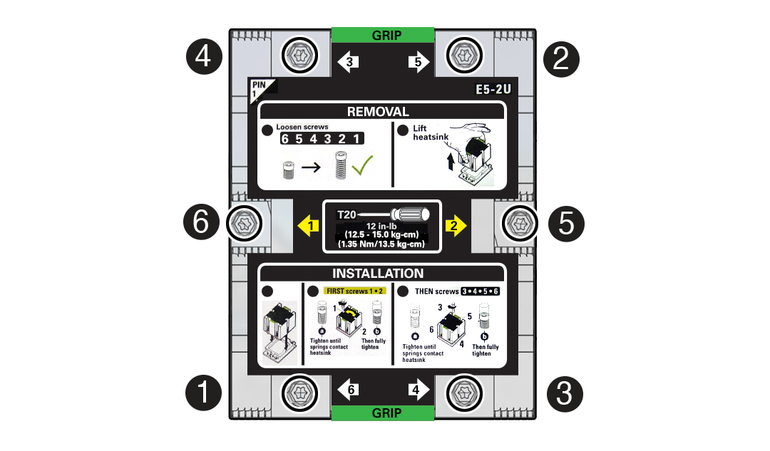
    A label on top of the heatsink provides additional detail.


    Description of aog-214_heatsink-screw-remove-order.png follows
    Description of the illustration aog-214_heatsink-screw-remove-order.png
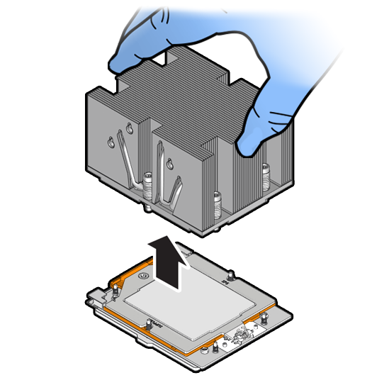
  4. Lift the heatsink from the socket.

    Caution:

    There is a thin layer of thermal grease between the heatsink and the processor. Do not allow the thermal grease to contaminate the workspace or other components.

    Note:

    Always grip the heatsink along the axis of the fins to prevent damage.


    Description of aog-217_remove-processor.png follows
    Description of the illustration aog-217_remove-processor.png
  5. Place the heatsink, facing up, on a work surface.
  6. Wipe the heatsink with a dry wipe to remove most of the thermal grease. Then clean off the thermal interface material (TIM) using the supplied alcohol wipes until there is no grease remaining.

    Description of aog-258_clean-processor-heatsink.png follows
    Description of the illustration aog-258_clean-processor-heatsink.png

    Caution:

    Failure to clean thermal grease from the heatsink could result in the accidental contamination of the processor socket or other components. Be careful not to get the grease on your fingers, as this could result in contamination of components.
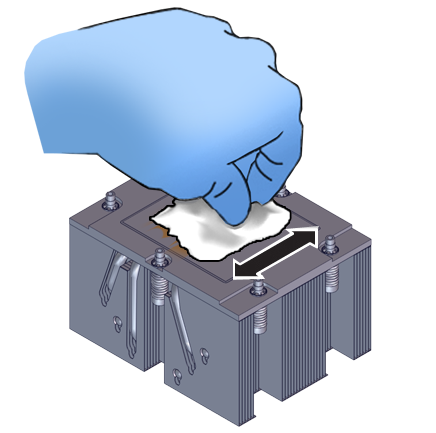
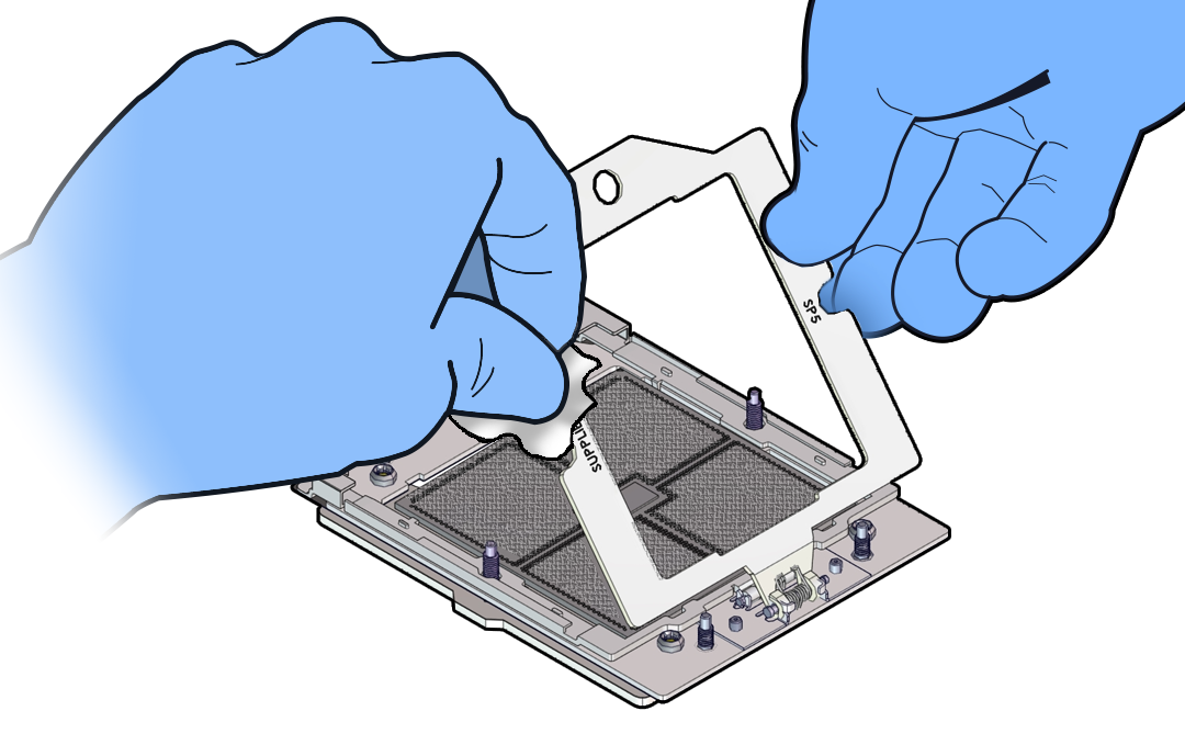
  7. Wipe the top of the processor with a dry wipe to remove most of the thermal grease.

    Caution:

    If thermal grease falls into the socket, there is no way to remove it without damaging the socket. Remove thermal grease from the processor and any on the socket assembly before removing the carrier with the processor.


    Description of aog-259_wipe-processor-lid.png follows
    Description of the illustration aog-259_wipe-processor-lid.png
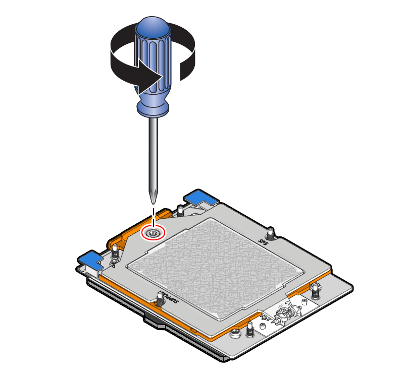
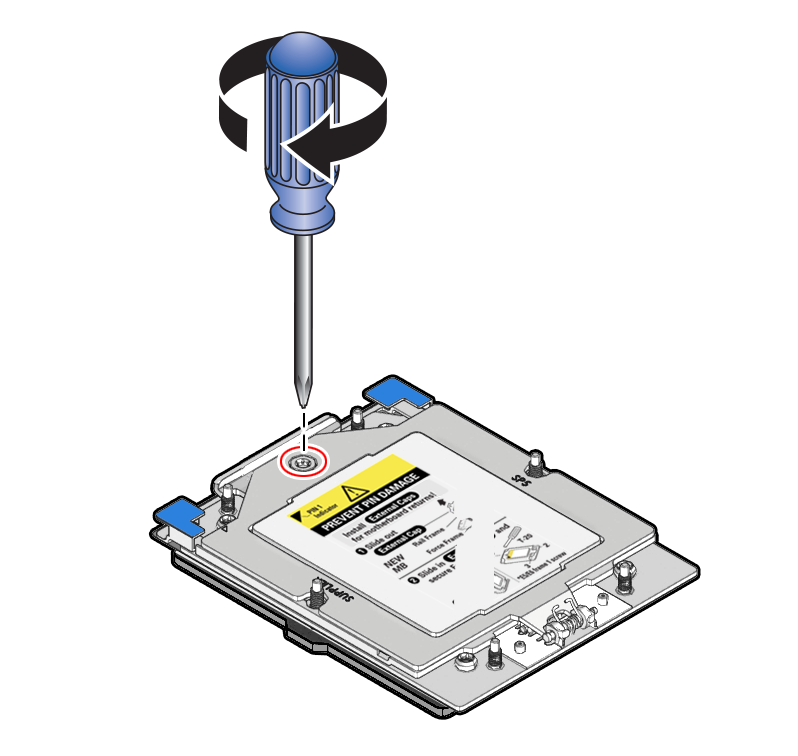
  8. Unscrew the socket Force Frame.
    Using a Torx T20 screwdriver, loosen the captive Force Frame Retention Screw that secures the Force Frame to the socket.
    Description of aog-260_loosening-sequence-proc.png follows
    Description of the illustration aog-260_loosening-sequence-proc.png
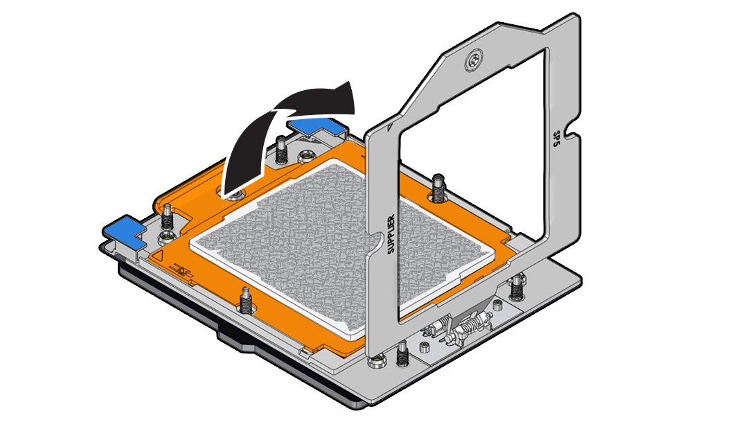
  9. Lift the Force Frame to the open position.

    Apply counter-pressure to the Force Frame when opening.


    Description of aog-261_open-force-frame.png follows
    Description of the illustration aog-261_open-force-frame.png
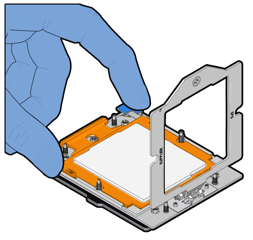
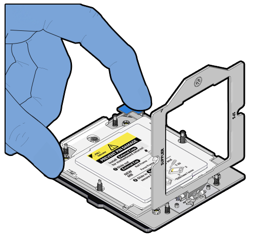
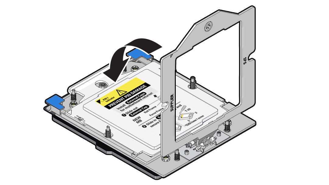
  10. Open the Rail Frame.
    Squeeze the blue tabs to release the Rail Frame.
    Description of aog-262_squeeze-frame-tabs.png follows
    Description of the illustration aog-262_squeeze-frame-tabs.png
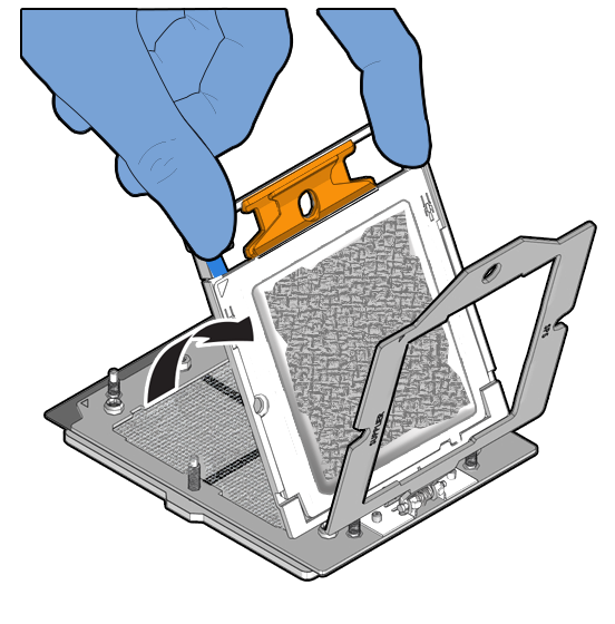
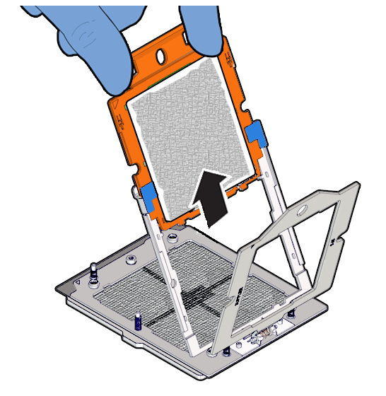
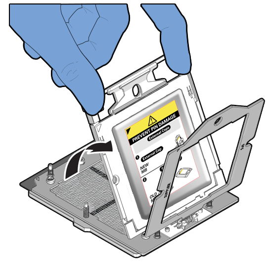
  11. Lift the Rail Frame and slide out the carrier frame package.

    Lift the Rail Frame by holding its lift tabs and rotating the Rail Frame to its near vertical position.


    Description of aog-276_lift-processor-frame.png follows
    Description of the illustration aog-276_lift-processor-frame.png

    Note:

    The Rail Frame is spring-loaded. Hold on to the Rail Frame as it releases from the socket frame, when rotating it to the vertical position.

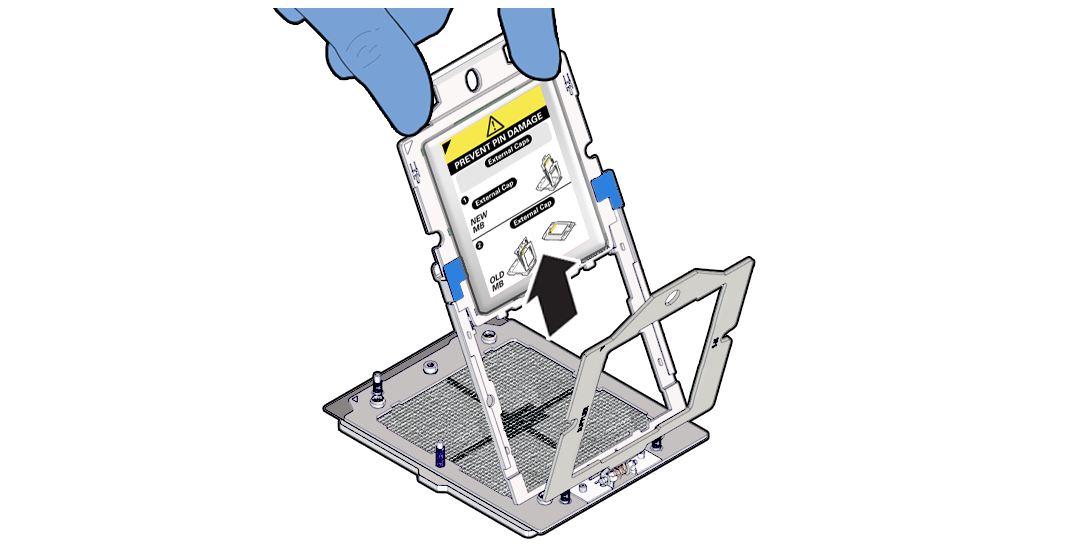
    Slide the carrier frame package holding the processor out.


    Description of aog-291_slide-proc-out1.png follows
    Description of the illustration aog-291_slide-proc-out1.png
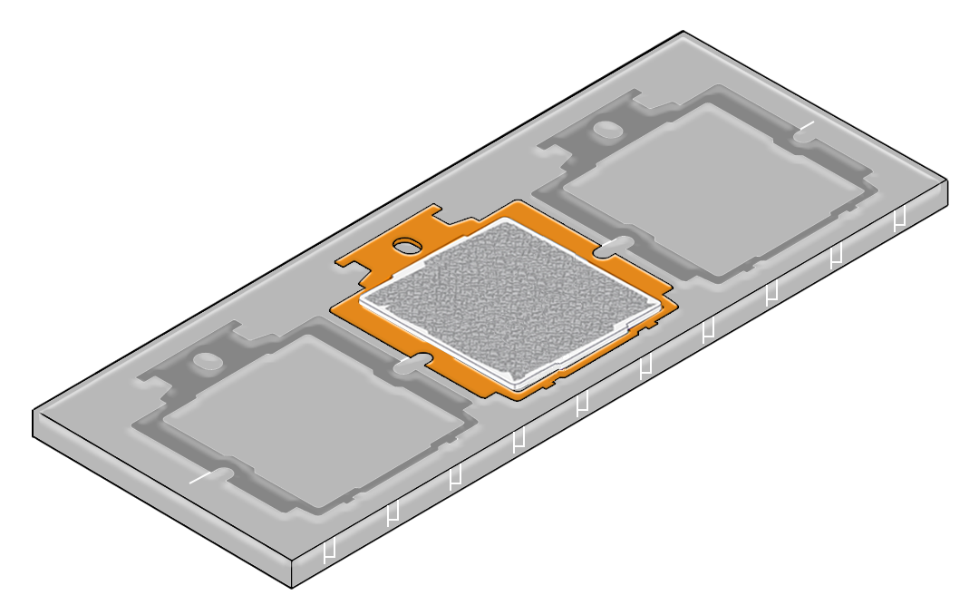
  12. Place the carrier frame package in an appropriate tray.
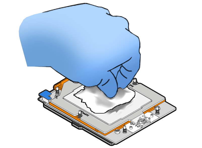
  13. Wipe the Force Frame (retention frame) with a dry wipe followed by a wipe with a small amount of isopropyl alcohol.

    Caution:

    If thermal grease falls into the socket, there is no way to remove it without damaging the socket.


    Description of aog-303_wipe-retention-frame-1.png follows
    Description of the illustration aog-303_wipe-retention-frame-1.png
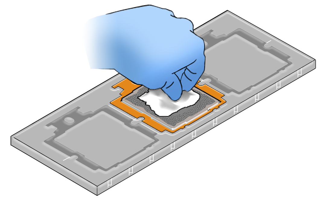
  14. Clean off any remaining thermal interface material (TIM) from the processor using the supplied alcohol wipes.

Install a Processor

  • Use ESD gloves (not latex or vinyl), if possible, when handling the processor.

  • Obtain a torque driver set to 12 in-lb (inch-pound or 1.35 Nm/13.5 kg-cm) force with a T20 Torx bit for processor and heatsink installation.

  • All of the old thermal interface material (TIM) should have been removed. Failure to remove/replace the old TIM can result in processor overheating.

  • Be careful not to touch the processor socket pins.

    Caution:

    The processor socket pins are very fragile. A light touch can bend the processor socket pins beyond repair.
  • If you are replacing a processor, ensure that the replacement processor is identical to the processor that was removed. A list of supported processors can be found in the Owner's Guide.

  1. Attach an antistatic wrist strap to your wrist, and then to a metal area on the chassis.
  2. Open the new processor package.

    Ensure that the replacement processor is identical to the processor that was removed.

    The processor comes preinstalled on a special carrier to ensure safe handling. Do not remove the processor from its carrier.


    Description of mm-11114_processor-carrier-package.png follows
    Description of the illustration mm-11114_processor-carrier-package.png

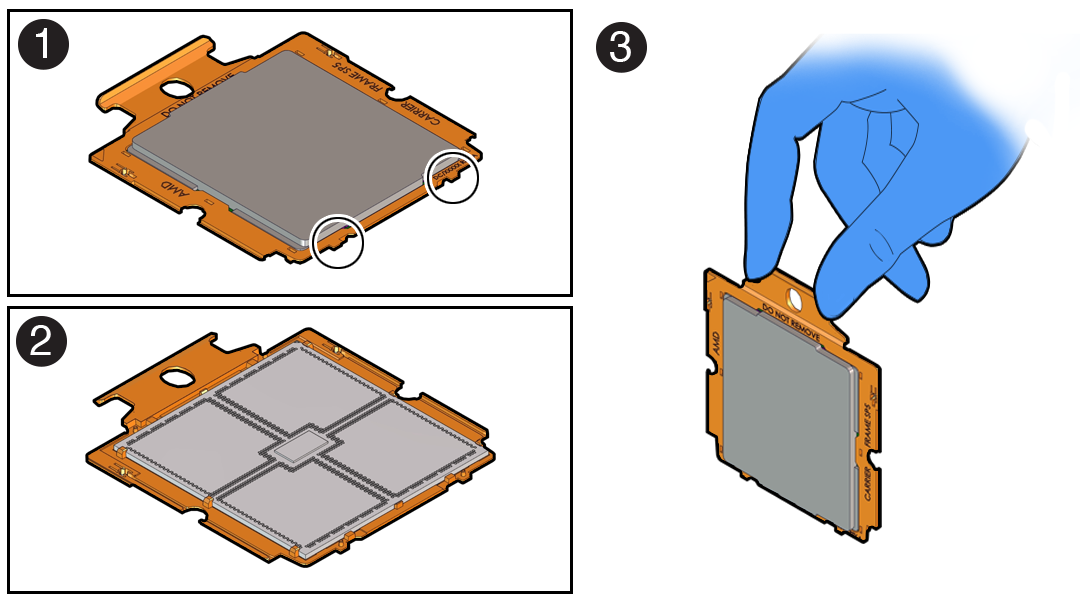
    Note the orientation and correct handling of the processor package.


    Description of aog-289_processor-carrier-features.png follows
    Description of the illustration aog-289_processor-carrier-features.png
    Callout Description

    1

    Top of processor carrier (insertion tabs are circled)

    2

    Bottom of processor carrier (contacts the socket)

    3

    Use of the processor carrier handle

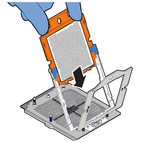
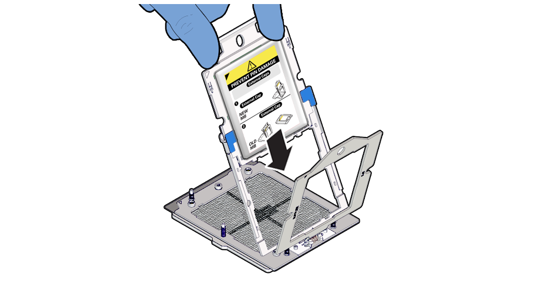
  3. Holding the processor carrier by its handle, slide it into the socket Rail Frame.

    Description of aog-291_slide-proc.png follows
    Description of the illustration aog-291_slide-proc.png

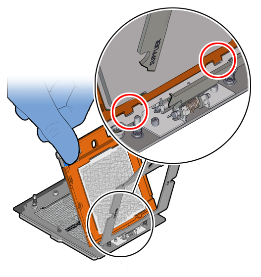
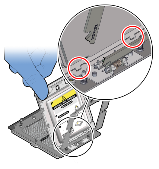
    Ensure that the two insertion tabs at the bottom of the processor carrier are inserted into the tab slots in the Rail Frame.


    Description of aog-292_slide-processor.png follows
    Description of the illustration aog-292_slide-processor.png
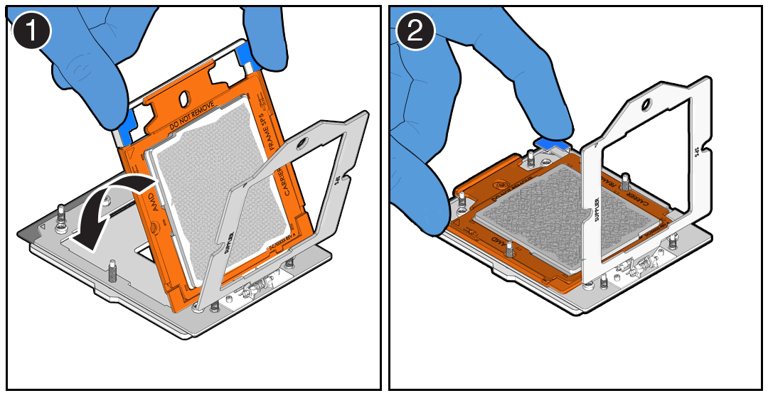
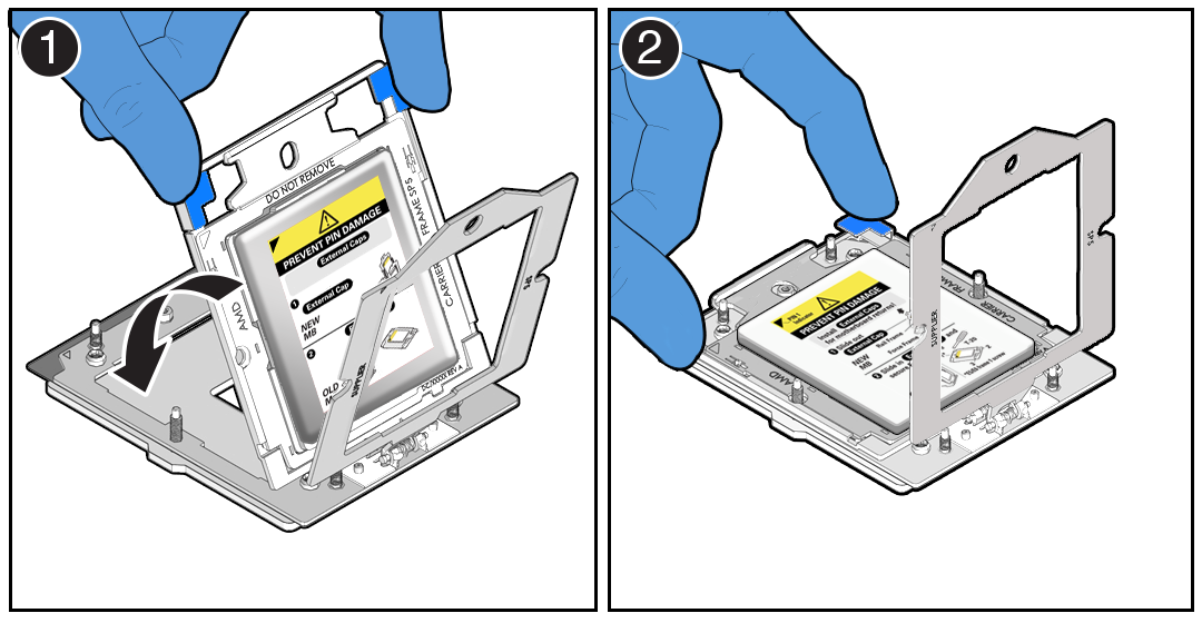
  4. Grasping the Rail Frame edge [1], rotate the Rail Frame down to the closed position [2].
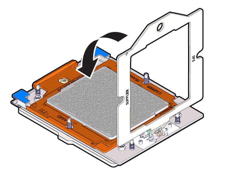
  5. Rotate the Force Frame down to its closed position on the socket stiffener frame.
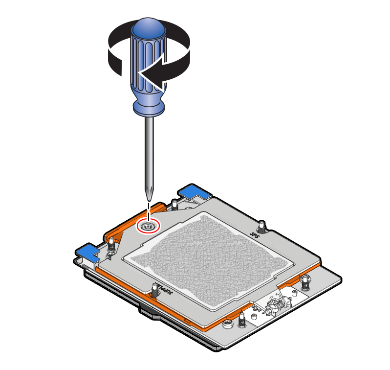
  6. Using a torque driver set to 12 in-lb (inch-pound) or 1.35 Nm/13.5 kg-cm force with a Torx T20 bit, fully tighten the captive screw that secures the Force Frame to the socket stiffener frame.

    Use one hand to hold down the spring-loaded Force Frame until the screw is tightened.


    Description of aog-296_tightening-sequence-proc.png follows
    Description of the illustration aog-296_tightening-sequence-proc.png
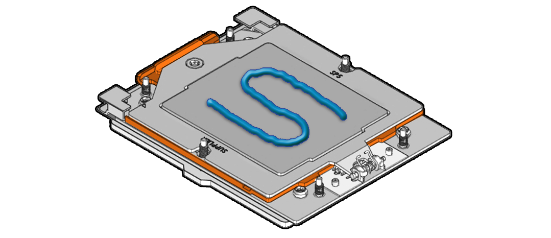
  7. Apply the thermal interface material (TIM).
    Using the supplied syringe, evenly apply all of the TIM in an "S" pattern centered on the top of the processor.

    Keep the "S" pattern inside a half inch of the processor edge so the TIM doesn't overflow and contaminate other parts of the processor housing.

    Note:

    Do not distribute the TIM. The pressure of the heatsink will do so for you when you install the heatsink.

    Description of aog-297_apply-thermal-grease.png follows
    Description of the illustration aog-297_apply-thermal-grease.png
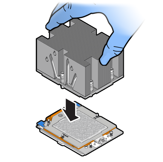
  8. Carefully lower the heatsink on to the six socket heatsink attachment studs.

    The heatsink is keyed to go on only one way. The captive screws that attach to the pin 1 end of the socket stiffener frame are closer together than the captive screws that attach at the opposite end of the stiffener frame. Screws 1 and 2 are slightly longer than screws 3, 4, 5, and 6.


    Description of aog-298_install-processor.png follows
    Description of the illustration aog-298_install-processor.png
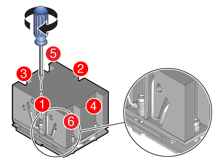
  9. Using torque driver set to 12 in-lb (13.5 kg-cm) to 13.02 in-lb (15.0 kg-cm) force with a Torx T20 bit, tighten the heatsink module to the socket as shown in the following illustration.
  10. Return the server to operation.
    1. Install the air baffle.
    2. Install the server top cover.
    3. Return the server to the normal rack position.
    4. Reconnect the power cords to the power supplies, and power on the server.
    5. Verify that the power supply AC OK LED is lit.
  11. Use Oracle ILOM to clear server processor faults.
    1. To show server faults: log in to the server as root using the Oracle ILOM CLI, and type the following command to list all known faults on the server:

      -> show /SP/faultmgmt

      The server lists all known faults, for example:

      -> show /SP/faultmgmt
        Targets:
            shell
            0 (/SYS/MB/P0)
        Properties:
        Commands:
            cd
            show

      Alternatively, log in to the Oracle ILOM service processor from the Oracle ILOM Fault Management Shell and issue the fmadm faulty command. For more information about how to use the Oracle ILOM Fault Management Shell and supported commands, see the Oracle ILOM User's Guide for System Monitoring and Diagnostics at Oracle ILOM Documentation.

    2. To clear the fault identified in previous step, type the following command: set command

      -> set /SYS/MB/P0 clear_fault_action=true

      For example:

      -> set /SYS/MB/P0 clear_fault_action=true
      Are you sure you want to clear /SYS/MB/P0 (y/n)? y
      Set ‘clear_fault_action’ to ‘true’

      Alternatively, to clear all known faults in the server, log in to the Oracle ILOM service processor from the Oracle ILOM Fault Management Shell and issue the fmadm repair command.

      For more information about how to use the Oracle ILOM Fault Management Shell and supported commands, see the Oracle ILOM User's Guide for System Monitoring and Diagnostics at Oracle ILOM Documentation.

Servicing the Fan Tray (FRU)

Perform tasks in this section to service the fan tray.

The fan tray might need to be removed when servicing the disk backplane and motherboard assembly. Removing the fan tray requires you to power off the server.

Caution:

Ensure that all power is removed from the server before removing or installing the disk backplane. You must disconnect the power cables before performing this procedure.

Caution:

These procedures require that you handle components that are sensitive to electrostatic discharge. This sensitivity can cause the component to fail. To avoid damage, ensure that you follow electrostatic discharge safety measures and antistatic practices. See Electrostatic Discharge Safety.

Remove the Fan Tray

Perform this procedure only when servicing disk backplane and motherboard assembly replaceable components.

  1. Remove all fan modules from the fan tray.
  2. Remove the air baffle.
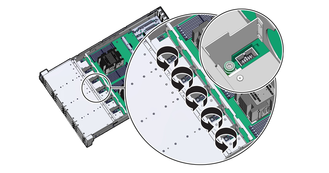
  3. Using a Torx T25 screwdriver, loosen the five spring-mounted screws that secure the fan tray to the server chassis.
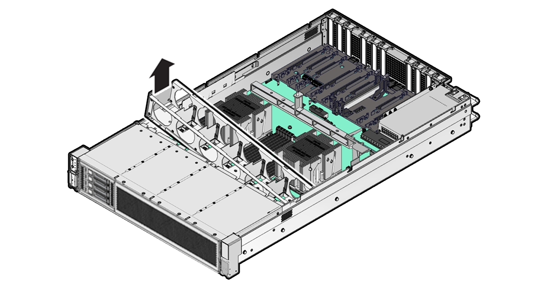
  4. When removing the fan tray, slightly tilt the fan tray to the left to decompress the cables, before removal.
    Ensure all motherboard cables are clear of the fan tray and fan tray gasket. Description of aog-117a_tilt-fan-tray_2.png follows
    Description of the illustration aog-117a_tilt-fan-tray_2.png
  5. Lift the fan tray from the server.
  6. Continue with the next step in the service procedure.

Install the Fan Tray

Perform this procedure only when servicing disk backplane and motherboard assembly replaceable components.

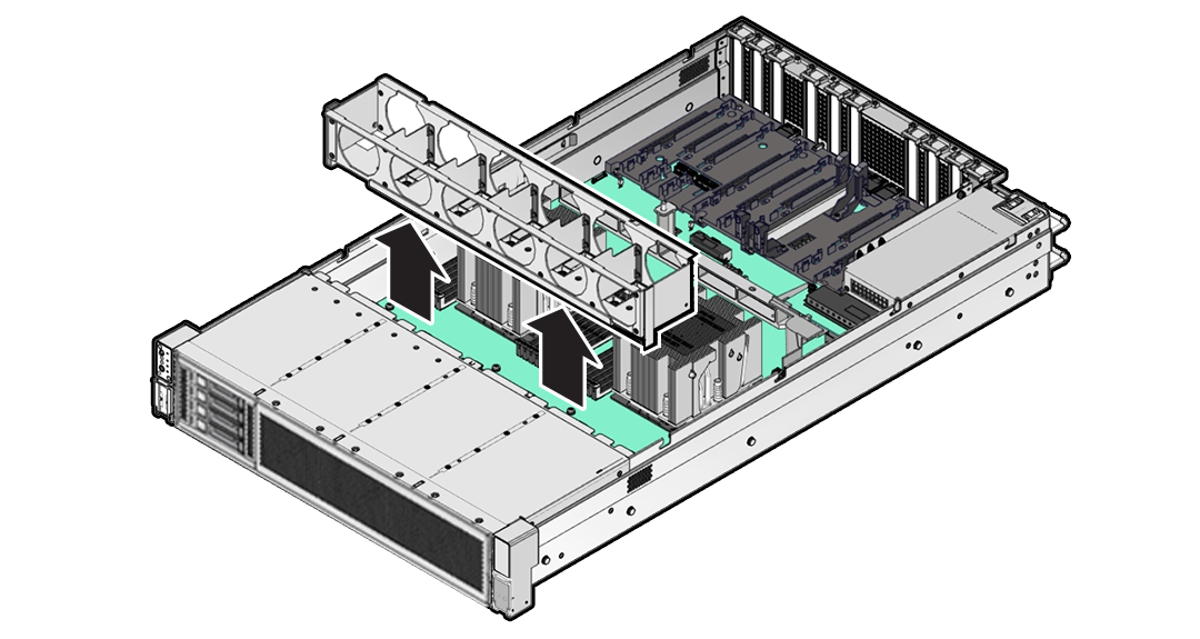
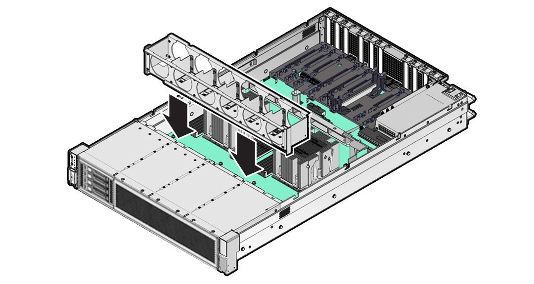
  1. Lower the fan tray into the server.
    Ensure all motherboard cables are clear of the fan tray and fan tray gasket. Description of aog-122a_install-fan-tray.png follows
    Description of the illustration aog-122a_install-fan-tray.png
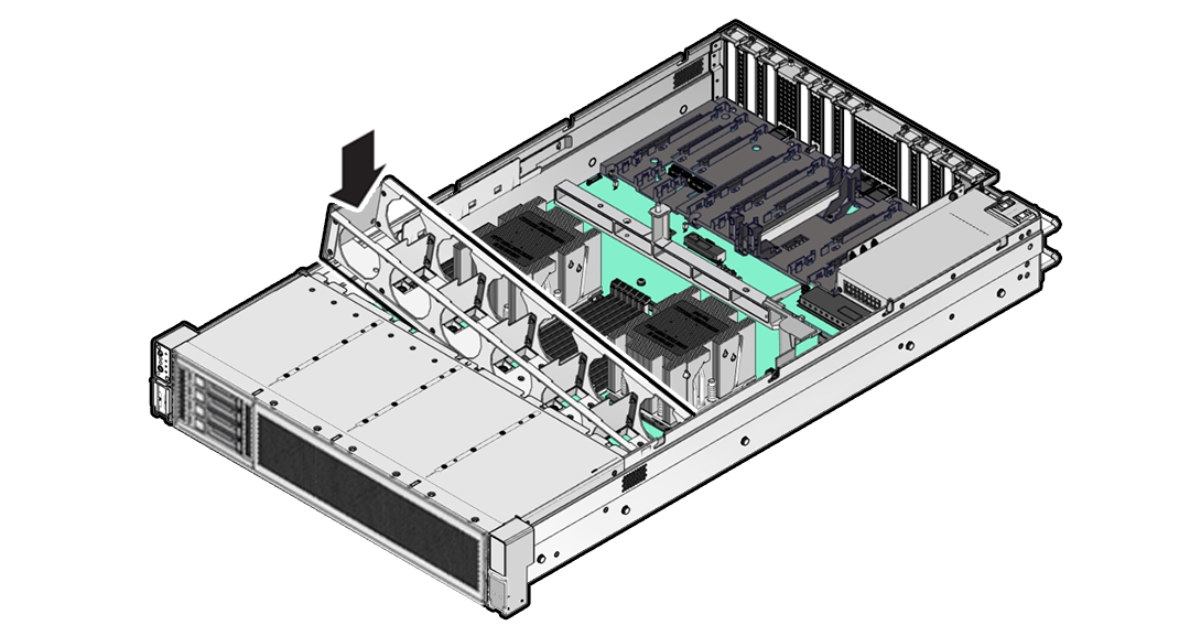
  2. When installing the fan tray, the fan tray should first be slightly tilted to the left to compress the cables, before the operation.
    Ensure all motherboard cables are clear of the fan tray and fan tray gasket. Description of aog-121a_tilt-install-fan-tray.png follows
    Description of the illustration aog-121a_tilt-install-fan-tray.png
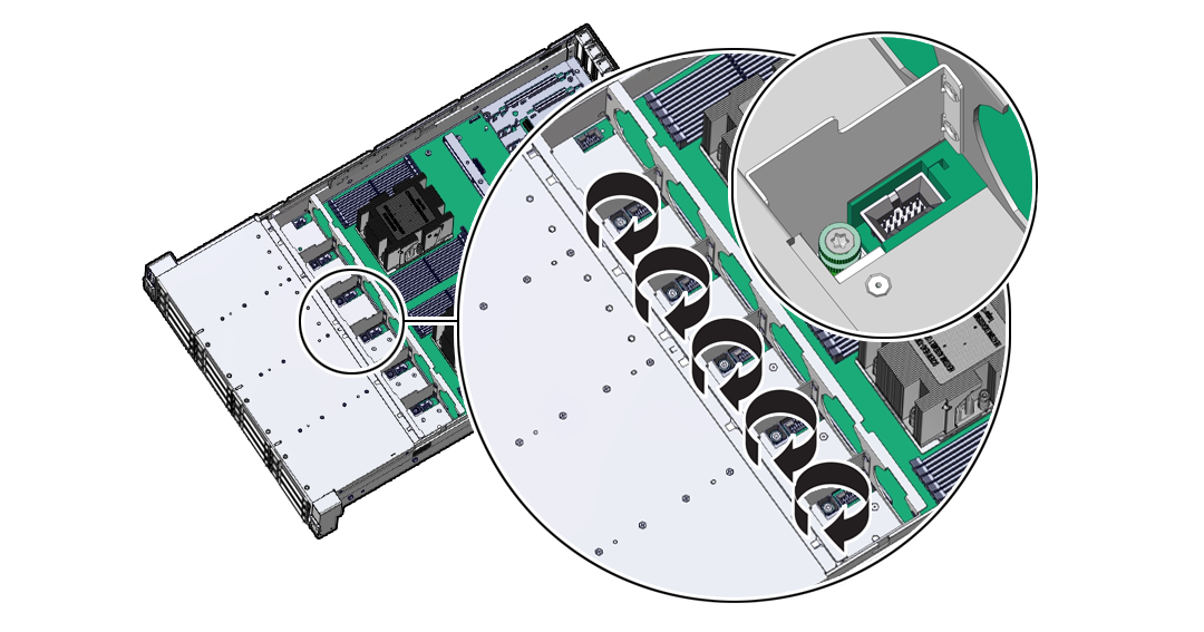
  3. Using a Torx T25 screwdriver, tighten the five spring-mounted screws that secure the fan tray to the server chassis.
  4. Install the fan modules into the fan tray.
  5. Install the air baffle.
  6. Continue with the next step in the service procedure.

Servicing the Disk Backplane (FRU)

Perform tasks in this section to service the disk backplane.

The disk backplane (DBP) is a replaceable component that requires you to power off the server before servicing.

Caution:

Ensure that all power is removed from the server before removing or installing the disk backplane. You must disconnect the power cables before performing this procedure.

Caution:

These procedures require that you handle components that are sensitive to electrostatic discharge. This sensitivity can cause the component to fail. To avoid damage, ensure that you follow electrostatic discharge safety measures and antistatic practices. See Electrostatic Discharge Safety.

Remove the 4-Drive Backplane

To remove the storage drive cage and 4-Drive disk backplane:

  1. Prepare the server for service.
    1. Power off the server.
    2. Disconnect the power cords from the power supplies.
    3. Extend the server into the maintenance position.
    4. Attach an antistatic wrist strap to your wrist, and then to a metal area on the chassis.
    5. Remove the server top cover.
    6. Remove the fan modules and tray from the server.
  2. Remove all NVMe storage drives from the server front panel and set them aside on an antistatic mat.

    To remove a drive, push the latch release button on the front of the drive to open the drive latch [1], grasp the latch, and pull the drive out of the drive slot [2]. Be sure to label the drives so you can later reinstall them into the same slots from which they were removed.


    Description of aog-272_remove-sff-drive.png follows
    Description of the illustration aog-272_remove-sff-drive.png
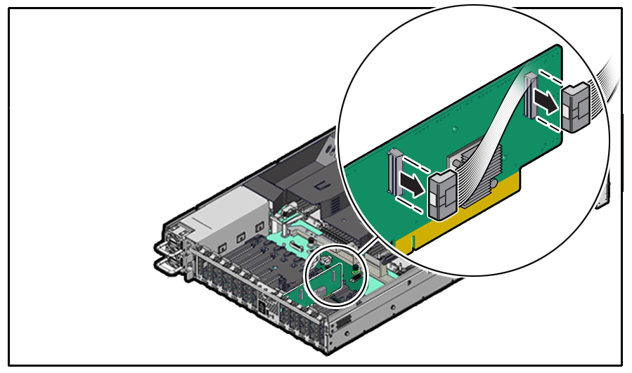
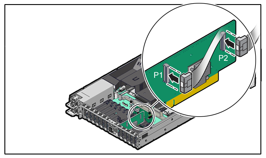
  3. Disconnect the Retimer cable from the Oracle Retimer card installed in PCIe slot 6.

    The Oracle Retimer card has a "Y" cable with two connections on the Retimer card. The other end connects to the disk backplane. If you need to remove the Oracle Retimer card to access the cables, see Remove a Half Height PCIe Card.


    Description of aog-270a_removing-retimer-cables.png follows
    Description of the illustration aog-270a_removing-retimer-cables.png
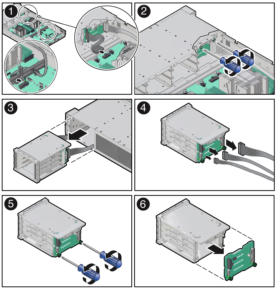
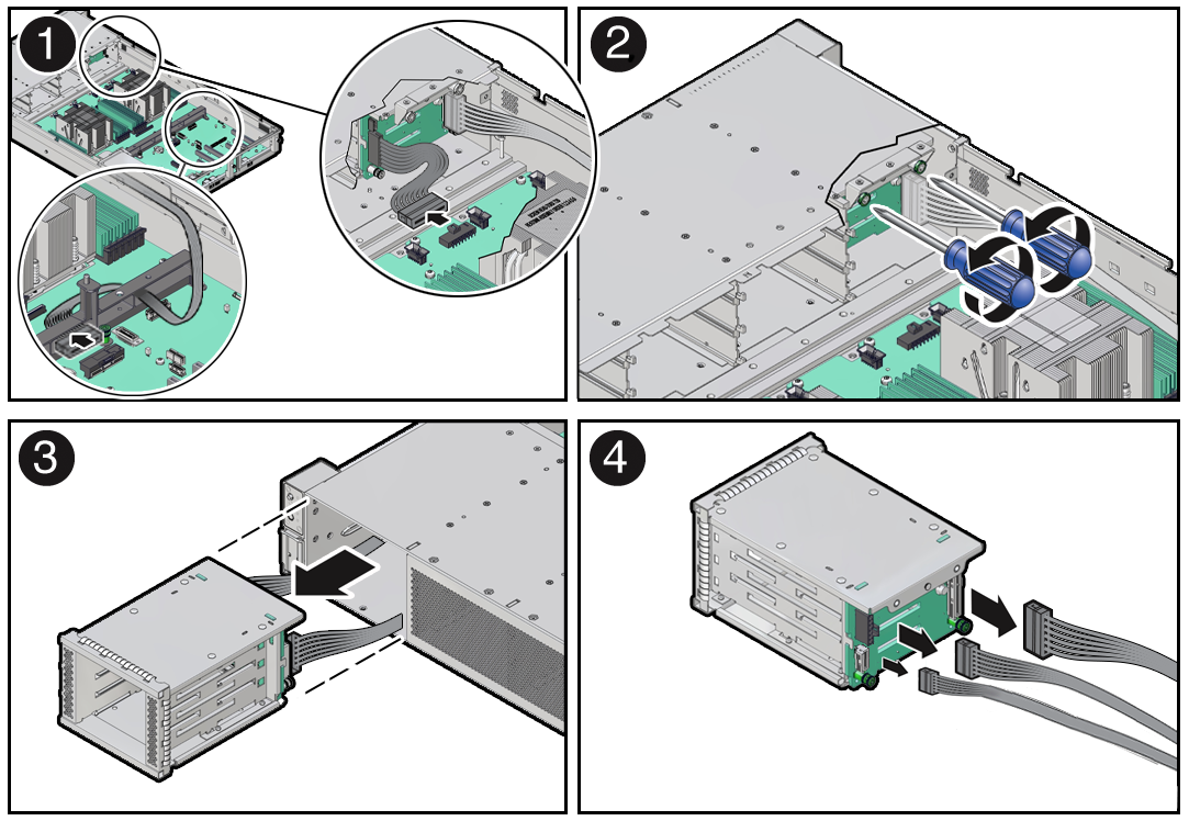
  4. Remove the storage drive cage from the chassis. Then remove the 4-Drive disk backplane from the storage drive cage.
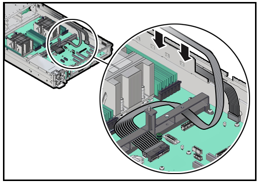
    1. Disconnect the disk backplane Power cable and the Aux Signal cable from the motherboard [1]. Also remove the Aux Signal cable and Retimer cable from the cable trough on the side of the chassis wall (on the left side when facing the front of the system).

      Note:

      Due to the lack of space, do not attempt to disconnect cables from the disk backplane at this time.


    2. Using a Torx T15 screwdriver, loosen the two spring-mounted screws that secure the storage drive cage in to the chassis [2].
    3. Ensure that the disk backplane cables are free from snagging motherboard components and gently pull the storage drive cage with cables attached through the front panel of the chassis [3].
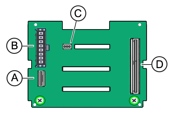
    4. Disconnect the disk backplane cables from the disk backplane and set them aside [4].

      As shown below, the disk backplane has four connectors to which cables are attached: the Aux Signal [A], Power [B], Temperature Sensor [C] and Retimer [D]. Press and hold the button on the connector to disengage the locking mechanism, then gently disconnect each cable from the disk backplane.


    5. Using a Torx T15 screwdriver, loosen the two spring-mounted screws that secure the disk backplane to the storage drive cage [5].
    6. Gently remove the disk backplane from the storage drive cage [6].
    7. Place the disk backplane on an antistatic mat.

Install the 4-Drive Backplane

To install the 4-Drive disk backplane and storage drive cage:

  1. Unpack the replacement 4-Drive disk backplane and place it on an antistatic mat.
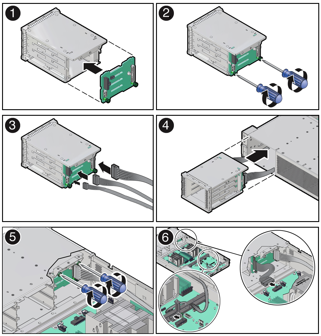
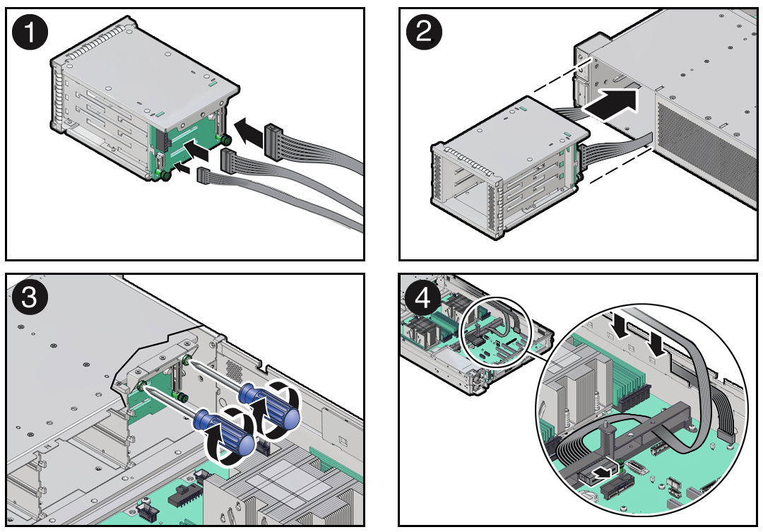
  2. Install the 4-Drive disk backplane on to the storage drive cage. Then reinstall the storage drive cage in to the chassis.
    1. Align the replacement disk backplane with the rear of the storage drive cage. Using a Torx T15 screwdriver, tighten the two spring-mounted screws to secure the disk backplane to the storage drive cage [1, 2].
    2. Reconnect the disk backplane cables to the disk backplane [3].

      As shown below, the disk backplane has four connectors to which cables are attached: the Aux Signal [A], Power [B], Temperature Sensor [C] and Retimer [D]. Attach cables to the appropriate connector.


    3. Align the storage drive cage with the opening in the front panel of the server. Pull the attached cables through the opening while gently pushing the storage drive cage in to the chassis until it is fully seated in the chassis [4].
    4. Using a Torx T15 screwdriver, tighten the two spring-mounted screws to secure the storage drive cage to the chassis [5].
    5. Reconnect the disk backplane Aux Signal cable and Power cable to their motherboard connectors [6].
    6. Then, gently insert the disk backplane Aux Signal and Retimer cables into the cable trough on the side of the chassis wall (on the left side when facing the front of the system).
  3. Reconnect the "Y" end of the Retimer cable to the Retimer card in PCIe slot 6.

    The cable should have labels that indicate which connector is P1 and P2. Connect those to the P1 and P2 connector sockets on the Retimer card.


    Description of aog-271a_installing-retimer-cables.png follows
    Description of the illustration aog-271a_installing-retimer-cables.png
  4. Reinstall all NVMe storage drives into the server front panel storage drive cage.

    With the drive latch in the open position, slide the drive into the slot until the drive is fully seated [1] and then close the drive latch to lock the drive in place [2].


    Description of aog-273_install-sff-drive.png follows
    Description of the illustration aog-273_install-sff-drive.png
  5. Return the server to operation.
    1. Install the fan tray and fan modules.
    2. Install the air baffle.
    3. Install the server top cover.
    4. Return the server to the normal rack position.
    5. Reconnect the power cords to the power supplies, and power on the server.
    6. Verify that the power supply AC OK LED is lit.

    Note:

    IMPORTANT: When the disk backplane is replaced, the key identity properties (KIP) of the backplane is programmed by Oracle ILOM to contain the same KIP as the other quorum member components. If you removed other quorum member components, you might need to manually program the product serial number (PSN) into the new backplane. For more information, see FRU Key Identity Properties (KIP) Automated Update.

Remove a Disk Backplane Cable

  1. Prepare the server for service.
    1. Power off the server.
    2. Disconnect the power cords from the power supplies.
    3. Extend the server to the maintenance position.
    4. Attach an antistatic wrist strap.
    5. Remove the server top cover.
    6. Remove the air baffle.
    7. Remove the fan modules and fan tray from the server.
  2. Disconnect the "Y" end of the Retimer cable from the Retimer card installed in PCIe slot 6.
  3. Remove the storage drive cage from the chassis and disconnect cables.
    1. Disconnect the disk backplane Power cable and the Aux Signal cable from the motherboard [1]. Also remove the Aux Signal and Retimer cables from the cable trough on the side of the chassis wall (on the left side when facing the front of the system).

      Note:

      Due to the lack of space, do not attempt to disconnect cables from the disk backplane at this time.


    2. Using a Torx T15 screwdriver, loosen the two spring-mounted screws that secure the storage drive cage in to the chassis [2].
    3. Ensure that the disk backplane cables are free from snagging motherboard components and gently pull the storage drive cage with cables attached through the front panel of the chassis [3].
    4. Disconnect the cable to be replaced from the disk backplane and set it aside [4].

      Note:

      Press and hold the button on the connector to disengage the locking mechanism, then gently pull the connector from the disk backplane.
    5. Place the storage drive cage on an antistatic mat.

Install a Disk Backplane Cable

  1. Unpack the replacement disk backplane cable and place it on an antistatic mat.
  2. Connect the replacement cable the disk backplane and reinstall the storage drive cage in to the chassis.
    1. Connect the replacement cable to the disk backplane [1].

      Note:

      The disk backplane Aux Signal, Power and Retimer cables will only fit into the connectors for which they are designed.


    2. Align the storage drive cage with the opening in the front panel of the server. Pull the attached cables through the opening while gently pushing the storage drive cage in to the chassis until it is fully seated in the chassis [2].
    3. Using a Torx T15 screwdriver, tighten the two spring-mounted screws to secure the storage drive cage to the chassis [3].
    4. Reconnect the disk backplane Aux Signal and Power cables to their motherboard connectors [4].
    5. Then reconnect the "Y" end of the Retimer cable to the Retimer card in PCIe slot 6.
    6. Slide the disk backplane Aux Signal and Retimer cables into the cable trough on the side of the chassis wall (on the left side when facing the front of the system).
  3. Return the server to operation.
    1. Install the fan tray and fan modules.
    2. Install the air baffle.
    3. Install the server top cover.
    4. Return the server to the normal rack position.
    5. Reconnect the power cords to the power supplies, and power on the server.
    6. Verify that the power supply AC OK LED is lit.

Servicing the Front LED Indicator Module (FRU)

Perform tasks in this section to service the front LED indicator module.

The front LED indicator module is a replaceable component that requires you to power off the server before servicing.

Caution:

Ensure that all power is removed from the server before removing or installing a front LED indicator module. You must disconnect the power cables before performing this procedure.

Caution:

These procedures require that you handle components that are sensitive to electrostatic discharge. This sensitivity can cause the component to fail. To avoid damage, ensure that you follow electrostatic discharge safety measures and antistatic practices. See Electrostatic Discharge Safety.

Remove the Front LED Indicator Module

  1. Prepare the server for service.
    1. Power off the server.
    2. Disconnect the power cords from the power supplies.
    3. Extend the server into the maintenance position.
    4. Attach an antistatic wrist strap to your wrist, and then to a metal area on the chassis.
    5. Remove the server top cover.
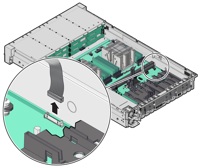
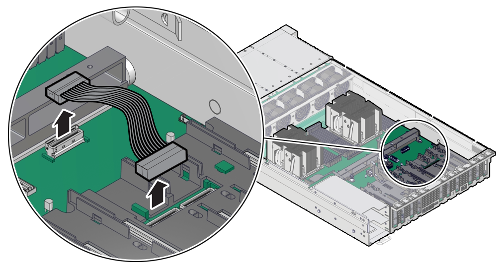
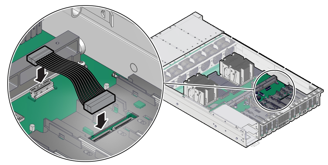
  2. Disconnect the LED indicator module cable from the motherboard.

    Note:

    To ease removal of the LED indicator module cable, you might need to lift the disk backplane auxiliary signal cable from the cable trough on the side of the chassis wall (on the left side when facing the front of the system).
    Description of mm-10578_disconnect-led-cable.png follows
    Description of the illustration mm-10578_disconnect-led-cable.png
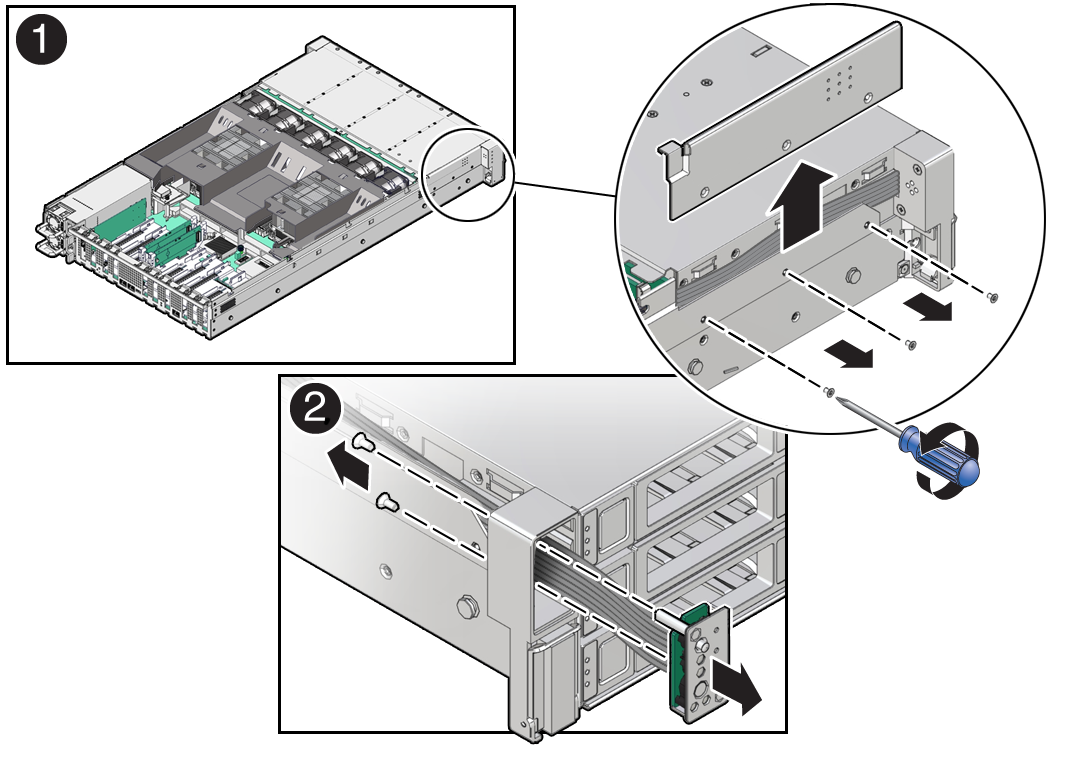
  3. Remove the three No. 2 Phillips screws that secure the FIM cable cover to the chassis [1]. Then lift up and remove the FIM cable cover from the FIM cable cover slot.
  4. Remove the front LED indicator module.
    1. Remove the two No. 2 Phillips screws that secure the LED indicator module to the server front panel [2].
    2. Remove the LED indicator module cable from the cable trough on the side of the chassis wall (on the left side when facing the front of the system).
    3. Then remove the LED indicator module and cable from the system by pulling it out through the server front panel [2].
    4. Place the LED indicator module on an antistatic mat.

Install the Front LED Indicator Module

  1. Unpack the replacement front LED indicator module and place it on an antistatic mat.
  2. Install the front LED indicator module.
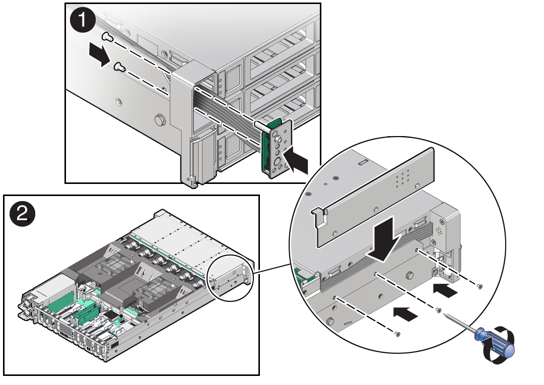
    1. Push the LED indicator module and cable through the LED housing on the server front panel. Then insert and tighten the two No. 2 Phillips screws to secure the LED indicator module to the server front panel [1].
    2. Place the FIM cable cover onto the chassis and install the three No. 2 Phillips screws to secure the cover to the chassis [2].
    3. Slide the LED indicator module cable into the cable trough on the side of the chassis wall (on the left side when facing the front of the system).

      Note:

      To ease installation of the LED indicator module cable, you might need to lift the disk backplane auxiliary signal cable from the left-side cable trough.
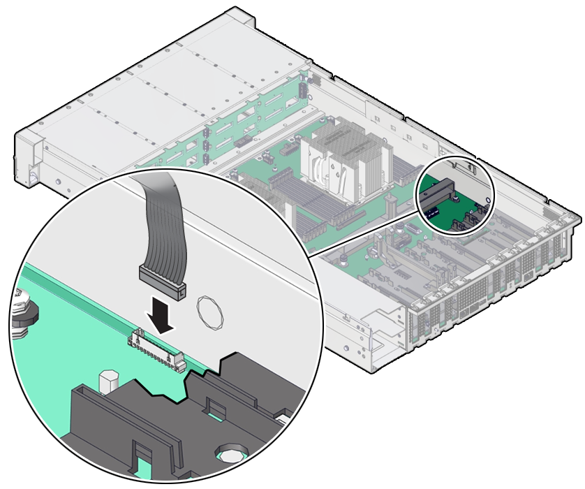
  3. Reconnect the LED indicator module cable to the motherboard.
  4. Return the server to operation.
    1. Install the server top cover.
    2. Return the server to the normal rack position.
    3. Reconnect the power cords to the server power supplies, and power on the server.
    4. Verify that the power supply AC OK LED is lit.

Servicing the PCIe Slot Flyover Cable (FRU)

Perform tasks in this section to service the PCIe Slot Flyover Cable.

Remove the PCIe Flyover Cable

The PCIe Flyover cable is required to provide x16 functionality to PCIe slot 6. The Oracle Database Appliance X10-S and X10-L include a PCIe retimer card in slot 6 that is used for front-mounted NVMe SSD storage.

Note:

The use of PCIe slot 7 is not supported for this product.
  1. Prepare the server for service.
    1. Power off the server.
    2. Disconnect the power cords from the power supplies.
    3. Extend the server into the maintenance position.
    4. Attach an antistatic wrist strap to your wrist, and then to a metal area on the chassis.
    5. Remove the server top cover.
  2. Locate the PCIe Flyover cable in the server.

    The PCIe Flyover cable is installed near the rear of the system system between the motherboard handle and behind PCIe slots 6 and 7. The PCIe Flyover cable is connected to the PCIe slot 6 connector.

  3. Disconnect and remove the PCIe Flyover cable.


    At each end of the cable, press and hold the metal clip to disengage the locking mechanism, then gently lift the PCIe Flyover cable from the connector.

Install the PCIe Flyover Cable

  1. Unpack the replacement PCIe Flyover cable.
  2. Connect the PCIe Flyover cable to the motherboard and the PCIe slot 6 connector.


    Plug each end of the cable into its connector until you hear an audible click.

  3. Return the server to operation.
    1. Install the server top cover.
    2. Return the server to the normal rack position.
    3. Reconnect the power cords to the server power supplies, and power on the server.
    4. Verify that the power supply AC OK LED is lit.

Servicing the Motherboard Assembly (FRU)

This section describes how to service the motherboard assembly.

The motherboard assembly is a replaceable component that requires you to power off the server before servicing.

Caution:

Ensure that all power is removed from the server before removing or installing the motherboard. You must disconnect the power cables before performing these procedures.

Caution:

These procedures require that you handle components that are sensitive to electrostatic discharge. This sensitivity can cause the component to fail. To avoid damage, ensure that you follow electrostatic discharge safety measures and antistatic practices. See Electrostatic Discharge Safety.

Remove the Motherboard Assembly

  • Use ESD gloves (not latex or vinyl), if possible, when handling components.

  • Obtain a Torx T20 screwdriver for processor socket external cap removal.

  • Obtain a Torx T25 screwdriver for motherboard removal.

  • Obtain a small flat blade screwdriver for light pipe removal from the old motherboard.

Caution:

Use the Oracle ILOM backup utility prior to removing the motherboard. This utility backs up the Oracle ILOM configuration of the service processor. Refer to Oracle ILOM Documentation.
  1. Prepare the server for service.
    1. Power off the server.
    2. Disconnect the power cords from the power supplies.
    3. Remove rear panel cables.
    4. Extend the server into the maintenance position.
    5. Attach an antistatic wrist strap to your wrist, and then to a metal area of the chassis.
    6. Remove the server top cover.
  2. Remove the air baffle.
  3. Remove the fan modules.
  4. Remove the fan tray.
  5. Remove all PCIe cards.
  6. Remove the power supplies.

    See Remove a Power Supply.

    Caution:

    During the motherboard removal procedure, it is important to label power supplies with the slot numbers from which they were removed (PS0, PS1). This is required because the power supplies must be reinstalled into the slots from which they were removed; otherwise, the server key identity properties (KIP) data might be lost. When a server requires service, the KIP is used by Oracle to verify warranty information. For more information on KIP, see FRU Key Identity Properties (KIP) Automated Update.
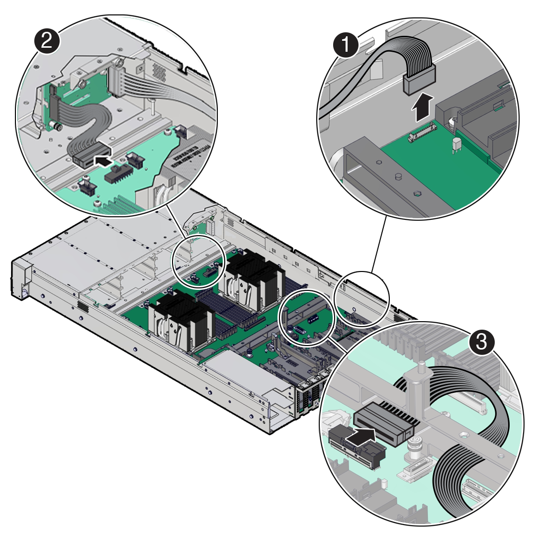
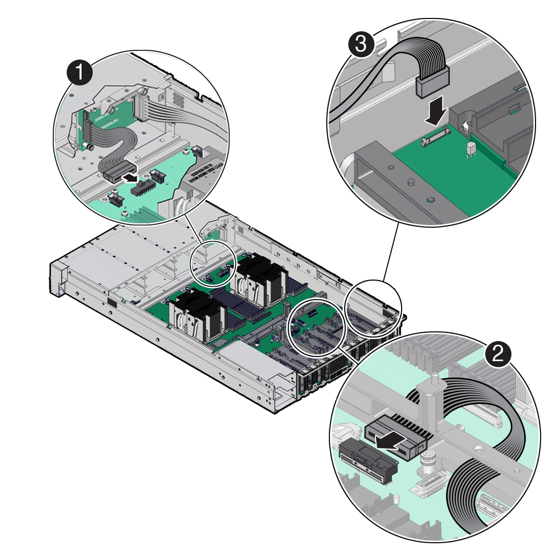
  7. Disconnect the front LED indicator module (FIM) ribbon cable [1], disk backplane Power cable [2] and disk backplane Aux Signal cable [3] from the motherboard.

    Note:

    Label any unlabeled cables to ease reconnecting them after the replacement motherboard is installed.

    Description of mm-10570a_disconnect-mb-cables-oda-x10.png follows
    Description of the illustration mm-10570a_disconnect-mb-cables-oda-x10.png
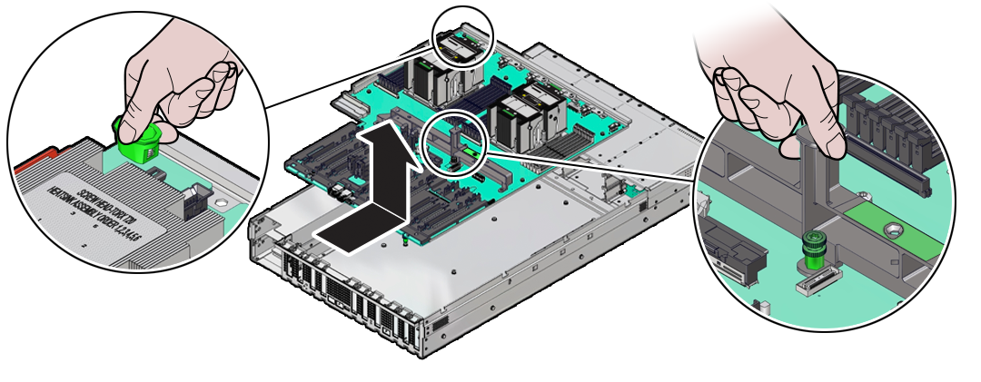
  8. Remove the cable guide on the side of the chassis wall (on the left side when facing the front of the system) that secures various cables as this can interfere with motherboard removal.
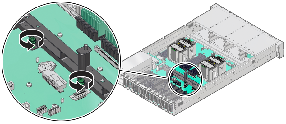
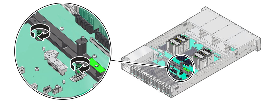
  9. Using a Torx T25 screwdriver, fully loosen the two captive screws that secure the motherboard mid-wall to the chassis.

    If you are not able to remove the motherboard, loosen the third screw in the midwall motherboard handle. After removing the motherboard, tighten the same screw.

    Description of aog-114_loosen-mb-screws.png follows
    Description of the illustration aog-114_loosen-mb-screws.png
  10. Remove the motherboard from the server with reusable components that populate the motherboard in place.

    Note:

    Move all cables out of the way so they do not interfere with the procedure. Be careful not to damage or break off the rear Locate light pipe LED indicator.

    1. Grasp the midwall motherboard handle labeled MB Handle.

      Hold the motherboard with the midwall motherboard handle and the small plastic motherboard handle.

      Description of aog-108_mb-handle.png follows
      Description of the illustration aog-108_mb-handle.png
    2. Carefully slide the motherboard forward, and while holding the motherboard mid-wall handle and small plastic motherboard handle, lift it out of the chassis.
    3. Place the motherboard assembly on an antistatic mat.
  11. Unpack and place the new motherboard assembly on an antistatic mat by the old motherboard.
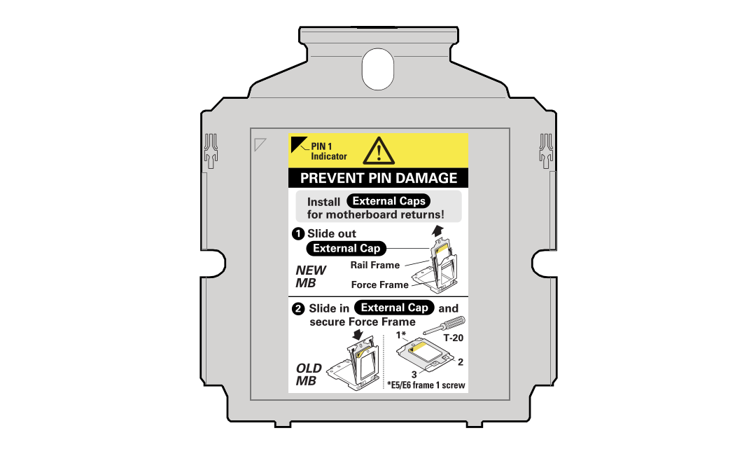
  12. Remove the External Cap(s) from the new replacement motherboard:

    The external cap is used to protect the socket pins if the processor is not installed. It must be removed before a processor can be installed. The following figure shows the External Cap.

    Description of mm-11100_processor-external-cap-2.png follows
    Description of the illustration mm-11100_processor-external-cap-2.png
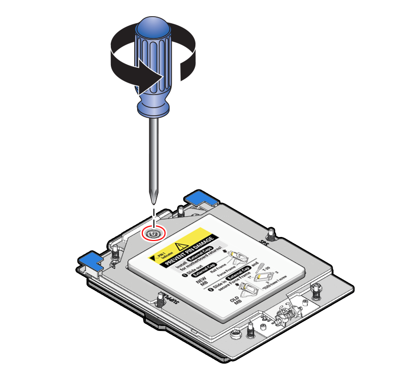
    1. Unscrew the socket Force Frame.

      Using a Torx T20 screwdriver, fully loosen the captive Force Frame Retention Screw that secures the Force Frame to the socket. Apply counter-pressure to the spring-loaded force frame when opening.

      Description of aog-235_loosening-sequence-cap.png follows
      Description of the illustration aog-235_loosening-sequence-cap.png
    2. Lift the force frame to the open position.
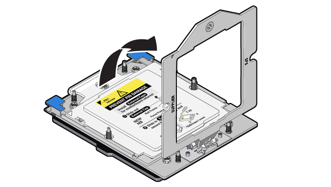
    3. On the socket, open the Rail Frame.

      Squeeze the blue tabs to release the rail frame.

      Description of aog-237_squeeze-frame-tabs-1-1.png follows
      Description of the illustration aog-237_squeeze-frame-tabs-1-1.png

      Lift the processor rail frame by holding its lift tabs and rotating the rail frame to its near vertical position.

      Note:

      The rail frame is spring-loaded. Hold on to the rail frame as it releases from the socket frame, when rotating it to the vertical position.
      Description of aog-238_lift-processor-frame-1.png follows
      Description of the illustration aog-238_lift-processor-frame-1.png
    4. Holding the socket cover external cap by its handle, slide the External Cap up and out of the Rail Frame.

      Caution:

      Return the motherboard if the pins are damaged. The processor socket pins are very fragile. A light touch can bend the processor socket pins beyond repair.
      Description of aog-239_slide-cap-1.png follows
      Description of the illustration aog-239_slide-cap-1.png

      Retain the external cap. Do not attempt to reinstall it. The cap will need to be placed on the processor socket of the old motherboard. This will prevent damage during shipping back to the Service Center for motherboard failure analysis.

    5. If you have a two processor system, repeat steps 12a through 12d to remove the second processor External Cap from the new motherboard.
  13. Remove the following reusable components from the old motherboard and install them onto the new motherboard.
    1. Move the motherboard PCIe Flyover cable from the old motherboard to the new motherboard.
    2. Move all DIMMs from the old motherboard to the new motherboard.

      Install the DIMMs only in the slots (connectors) that correspond to the slots from which they were removed. Performing a one-to-one replacement of the DIMMs significantly reduces the possibility that the DIMMs will be installed in the wrong slots. If you do not reinstall the DIMMs in the same slots, server performance might suffer and some DIMMs might not be used by the server.

      See Identify and Remove a DIMM and Install a DIMM.

    3. Move all M.2 SSD flash risers from the old motherboard to the new motherboard.

      Each flash riser board contains a single M.2 SSD. You do not need to remove the M.2 SSD from the flash riser board when moving it to the new motherboard. However, you must install the flash riser boards into the same slots on the new motherboard as they were installed on the old motherboard.

      See Remove a Flash Riser Board and Install a Flash Riser Board.

    4. Move each processor and heatsink from the old motherboard to the new replacement motherboard.

      Be sure to install each processor into the same socket on the new motherboard as it was installed in on the old motherboard.

      See Identify and Remove a Processor and Install a Processor.

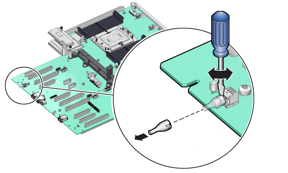
  14. Check to see if the replacement motherboard has a Locate light pipe installed, if not do the following:
    1. Insert a flat tool such as a screwdriver or penknife blade between the light pipe housing and the light pipe.

      Caution:

      Equipment damage. The light pipe is fragile. Handle it carefully.
      Description of mm-10597_replace-light-pipe.png follows
      Description of the illustration mm-10597_replace-light-pipe.png
    2. Twist the tool back and forth to release the light pipe from the housing.
    3. Pull the light pipe away from the housing.
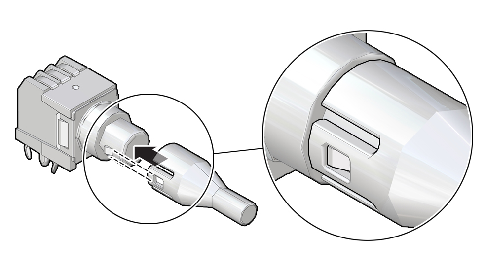
    4. Install the light pipe on the replacement motherboard by first matching the rectangular holes on the outside of the light pipe with the retaining clips on the housing
    5. Push the light pipe onto the housing until the clips latch in the holes.
  15. Install the external socket caps you removed earlier from the new motherboard and install them on the vacant sockets of the old motherboard.
    1. Holding the External Cap by its handle, slide it into the processor rail frame on the old motherboard.
      Description of aog-240_slide-cap-1.png follows
      Description of the illustration aog-240_slide-cap-1.png

      Ensure that the two insertion tabs at the bottom of the External Cap are inserted into the slots in the rail frame.

      Description of aog-241_slide-cap.png follows
      Description of the illustration aog-241_slide-cap.png
    2. Grasping the rail frame edge [1], rotate the rail frame to the closed position [2].
    3. Rotate the force frame to its closed position on the socket stiffener frame.
    4. Using a torque driver set to 12 in-lb (inch-pound) (1.35 Nm/13.5 kg-cm) with a Torx T20 bit, fully tighten the captive screw that secures the force frame to the socket stiffener frame.

      Use one hand to hold down the spring-loaded force frame until the screw is tightened.

      Description of aog-300_tightening-sequence-cap-1.png follows
      Description of the illustration aog-300_tightening-sequence-cap-1.png
    5. Repeat steps 15a through 15d if your system had a second processor.
    6. Place the old motherboard in the box that the new motherboard came in and return it to the Oracle Service Center for failure analysis.

Install the Motherboard Assembly

  • Use ESD gloves (not latex or vinyl), if possible, when handling components.

  • Obtain a Torx T25 screwdriver for motherboard installation.

  1. Attach an antistatic wrist strap to your wrist, and then to a metal area on the chassis.
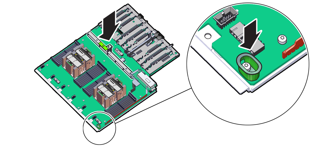
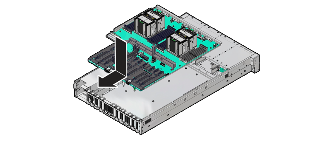
  2. Carefully lift and place the motherboard assembly into the chassis.

    While holding the motherboard mid-wall handle with one hand and the small plastic handle at the front corner with the other, lower the motherboard into the chassis. You need to tilt the motherboard downward towards the back of the chassis so that it fits under the sheet metal housing for the power supply and then lay the motherboard flat into the server chassis. Slide the motherboard to the back of the server to engage the raised standoffs.

    Caution:

    Be careful not to damage the rear Locate Button/LED when placing the motherboard into the chassis.
    Description of aog-119_install-mb.png follows
    Description of the illustration aog-119_install-mb.png
  3. Using a Torx T25 screwdriver, tighten the two captive screws to secure the motherboard mid-wall to the chassis.
  4. Replace the cable guide on the side of the chassis wall (on the left side when facing the front of the system) that secures various cables against the chassis side wall.
  5. Reconnect the disk backplane Power cable [1], disk backplane Aux Signal cable [2] and front LED indicator module (FIM) ribbon cable [3] to their connectors on the motherboard.
  6. Reinstall PCIe cards.
  7. Reinstall the fan tray.
  8. Reinstall the fan modules.
  9. Reinstall the air baffle.
  10. Reinstall the power supplies.

    See Install a Power Supply.

    Caution:

    When reinstalling power supplies, it is important to reinstall them into the slots from which they were removed during the motherboard removal procedure; otherwise, the server key identity properties (KIP) data might be lost. When a server requires service, the KIP is used by Oracle to verify warranty information. For more information on KIP, see FRU Key Identity Properties (KIP) Automated Update.
  11. Return the server to operation.
    1. Install the server top cover.
    2. Return the server to the normal rack position.
    3. Reconnect the power cords to the power supplies, and power on the server.
    4. Verify that the power supply AC OK LED is lit.

Component Fault Management

Perform component fault management on Oracle Database Appliance systems.

Typically, when a faulty component is replaced and the server is returned to service, the fault state of the component in Oracle ILOM is automatically cleared and the component Service Required indicator will turn off. This is the default behavior for all components that have an embedded FRU serial number in the component firmware.

For replaced components that do not have an embedded FRU serial number, or do not automatically clear their fault state after the component has been repaired and the server is returned to service, you can use Oracle ILOM command line interface to manually clear the fault state. Use the following syntax:

set /path_to_target clear_fault_action=true

Where path_to_target is the path to the component (such as a DIMM) that had the fault.

In addition, the Fault Management shell can also be used. Use of the Fault Management shell is reserved for Oracle Service. For more information on component fault management:

Refer to the Oracle ILOM User's Guide for SystemMonitoring and Diagnostics available in the Oracle ILOM Documentation Library for your version of Oracle ILOM.