Appendix C Connectivity Diagrams
Oracle Private Cloud Appliance exists in two different types of network architecture. One is built around a physical InfiniBand fabric; the other relies on physical high speed Ethernet connectivity. While the two implementations offer practically the same functionality, there are visible hardware and configuration differences.
The network architecture differences also affect the options to connect external storage hardware. The Oracle Fabric Interconnect F1-15, the heart of the network configuration of InfiniBand-based systems, offers physical connectors to attach external InfiniBand and Fibre Channel storage devices.
The diagrams in this section apply to systems with an InfiniBand-based network architecture, controlled by means of a pair of Fabric Interconnects.
C.1 InfiniBand-based Network Architecture Diagrams
C.1.1 External Ethernet Connections
This section shows the external Ethernet connectivity of an Oracle Private Cloud Appliance using the Oracle Fabric Interconnect F1-15.
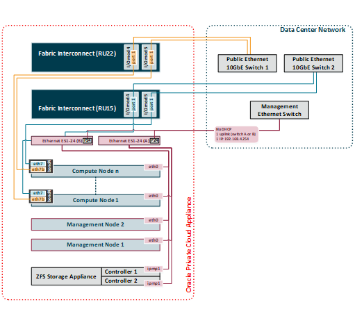
Diagram Notes
-
The connections in red in the left half of the diagram correspond with the out-of-band appliance management network
192.168.4.0/24. These are physical Ethernet ports connected with Ethernet cables to the two internally interconnected Oracle Switch ES1-24 switches. All appliance components and their ILOMs have a reserved IP address in this network. Only one address is available for customer use:192.168.4.254. -
You may connect to this management Ethernet network by choosing one of these methods:
-
Connect a workstation with an Ethernet cable plugged directly into the available port 19 in an Oracle Switch ES1-24. Statically assign IP address
192.168.4.254. -
Connect port 24 in one Oracle Switch ES1-24 – never both – to an Ethernet switch in your data center network. Use a workstation connected to the data center network and statically assign the IP address
192.168.4.254. Make sure that the management Ethernet switch used in this connection is configured to prevent DHCP leakage to the192.168.4.0/24subnet used by Oracle Private Cloud Appliance.
-
-
The connections in gold and blue on the left hand side of the diagram correspond with the default network
vm_public_vlan. This is the standard VLAN-enabled network for virtual machine traffic with public access. The compute node connections are bonds of two Ethernet vNICs that terminate on port 1 of the I/O modules 4 and 5 in both Fabric Interconnects. The underlying physical connection consists of redundant InfiniBand cabling. The physical 10GbE ports of the Fabric Interconnects are connected for redundancy to two next-level data center switches. -
The vNIC connections are distributed across the Fabric Interconnects and the I/O modules for maximum availability. If one of the redundant components fails at any level, be it an I/O module, an entire Fabric Interconnect or a next-level switch in the data center, the VMs always maintain an active external connection using either a blue or a red path. The uplinks to the data center switches are deliberately not cross-cabled to prevent that half of the compute nodes lose external connectivity if one of those switches fails.
-
All custom public networks follow the same principle as the default
vm_public_vlanshown in this diagram. However, for the custom networks additional bonded vNICs are created on the compute nodes, and additional I/O ports must be configured and cabled.
C.1.2 Virtual Networking
This section shows how Oracle Private Cloud Appliance networking is virtualized and configured through the Fabric Interconnects.
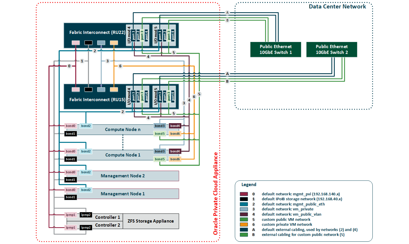
Diagram Notes
-
All virtual networks in the diagram connect bonds, consisting of two virtual interfaces on the nodes, to the Fabric Interconnects. Private networks, which provide internal connectivity only, terminate on the Fabric Interconnects and are not routed externally. Public networks terminate on the I/O modules and are routed externally across the 10GbE ports, which are cabled in a redundant configuration to dedicated Ethernet switches in the data center network. Only I/O modules 4 and 5 are shown in this diagram, but each Oracle Fabric Interconnect F1-15 installed in an Oracle Private Cloud Appliance rack contains two more I/O modules in slots 10 and 11, with four 10GbE ports each, which can be used in the same way.
The underlying physical connection of all virtual networking consists of redundant InfiniBand cabling. All internal and external connectivity is managed by the Fabric Interconnects.
-
The storage network is an IPoIB network that provides connectivity between the compute nodes, the management nodes and the internal ZFS storage appliance. All connected components use a network bond consisting of two virtual InfiniBand interfaces. The bonds have an IP address in the
192.168.40.0/24subnet. -
Apart from the storage network, all virtual networks in the diagram are Ethernet networks. All connected components use a network bond consisting of two vNICs. The Ethernet networks intended for both private and public VM connectivity only include the compute nodes. All VM networks are VLAN-enabled.
-
The virtual networks connecting the network bonds numbered 0-4 are configured by default on every Oracle Private Cloud Appliance. The network connecting all
bond6interfaces is an example of a custom private VM network. The network connecting allbond5interfaces is an example of a custom public VM network. This type of network requires the configuration of additional I/O ports, which must also be cabled to the next-level data center switches for public access.
C.1.3 External Storage Connections
This section shows how external storage is connected to the Fabric Interconnects in the Oracle Private Cloud Appliance.
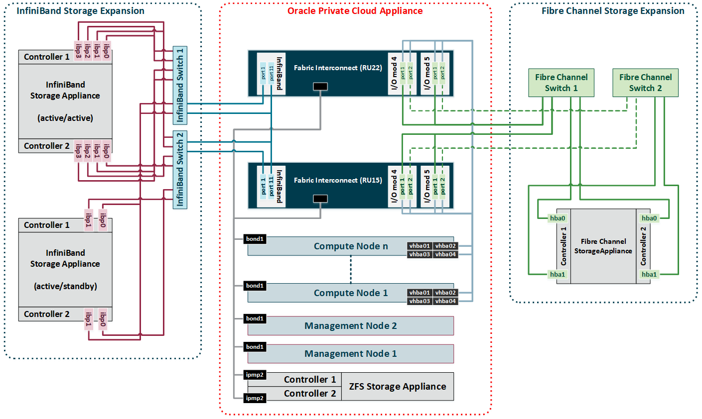
Diagram Notes
-
All nodes in the Oracle Private Cloud Appliance rack are connected to the IPoIB storage network (
192.168.40.0/24) through theirbond1interface, which consists of two virtual InfiniBand interfaces. For Fibre Channel storage connectivity all compute nodes have 4 virtual HBAs that terminate on the Fibre Channel I/O modules of the Fabric Interconnects. The underlying physical connection of all storage traffic consists of redundant InfiniBand cabling. All external storage connectivity is managed by the Fabric Interconnects. -
External InfiniBand storage, shown on the left-hand side of the diagram, can be connected to InfiniBand ports 1 and 11 of the Fabric Interconnects using one of these 3 supported cabling schemes:
-
In active/passive configuration, with both storage controllers cross-cabled to a pair of HA InfiniBand switches. Those switches are, in turn, cross-cabled to the available ports on the Fabric Interconnects.
In the diagram, this cabling scheme is represented by the example ZFS Storage Appliance placed in the bottom left corner.
-
In active/passive configuration, attached directly to the available ports on the Fabric Interconnects.
This cabling scheme is not shown in the diagram. However, it is identical to the active/passive example, but with cables running directly to the available ports on the Fabric Interconnects instead of the InfiniBand switches.
-
In active/active configuration, with both storage controllers using 4 cable connections to a pair of HA InfiniBand switches. Those switches are cross-cabled to the available ports on the Fabric Interconnects. The additional InfiniBand ports and 4 cables per storage controller are required to provide redundancy at the level of the HCAs as well as the network paths of both active controllers.
In the diagram, this cabling scheme is represented by the example ZFS Storage Appliance placed in the top left corner.
-
-
External Fibre Channel storage, shown on the right-hand side of the diagram, is connected to the I/O modules 3 and 12 of the Fabric Interconnects, but through one or two external Fibre Channel switches.
-
The minimum configuration uses 1 port per FC I/O module for a total of 4 physical connections to one external Fibre Channel switch. In this configuration both HBAs of both storage controllers are connected to the same Fibre Channel switch.
-
The full HA configuration uses both ports in each FC I/O module for a total of 8 physical connections: 4 per external Fibre Channel switch. In this configuration the HBAs of both storage controllers are cross-cabled to the Fibre Channel switches: one HBA is connected to switch 1 and the other HBA is connected to switch 2. The additional connections for the HA configuration are marked with dashed lines in the diagram.
-
-
The vHBAs in the servers and the Fibre Channel ports in the I/O modules of the Fabric Interconnects are connected according to a round-robin scheme for high availability. In a field installation the compute nodes are provisioned in random order. Therefore it is impossible to predict which nodes are connected to which I/O ports. The software does ensure that half the compute nodes follow the connection scheme of management node 1, while the other half follows the connection scheme of management node 2.
The connection scheme presented in Table C.1 shows that the four vHBAs in each server node are virtually cross-cabled to the Fabric Interconnects and their Fibre Channel I/O modules. To find out exactly how a particular compute node connects to the external FC storage you have to run the CLI command list wwpn-info.
Table C.1 Fibre Channel vHBA, I/O Port and Storage Cloud MappingvHBA
Fabric Interconnect
I/O Port
Storage Cloud
vhba01
ovcasw22r1 RU22
3/1 or 12/1
A
vhba02
ovcasw22r1 RU22
3/2 or 12/2
B
vhba03
ovcasw15r1 RU15
3/1 or 12/1
C
vhba04
ovcasw15r1 RU15
3/2 or 12/2
D
C.1.4 Custom and Host Networks
This section shows the various types of custom networks that are supported on an Oracle Private Cloud Appliance with Fabric Interconnects.
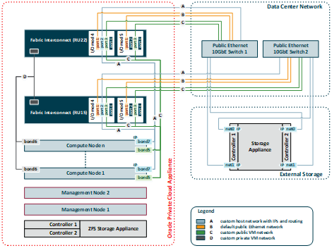
Diagram Notes
-
All custom networks are virtual Ethernet connections. They connect compute node bonds, consisting of two virtual interfaces on the nodes, to the Fabric Interconnects. The underlying physical connection is the InfiniBand fabric. Private custom networks, which provide internal connectivity only, terminate on the Fabric Interconnects and are not routed externally. Public custom networks terminate on the I/O modules and are routed externally across the 10GbE ports, which are cabled to Ethernet switches in the data center network. A public custom network can use one or more I/O ports.
-
The host network is a particular type of public custom network: its configuration contains additional parameters for subnet and routing. The servers connected to it also receive an IP address in that subnet, and consequently can connect to an external network device.
-
Only I/O modules 4 and 5 are shown in this diagram, but each Oracle Fabric Interconnect F1-15 installed in an Oracle Private Cloud Appliance rack contains two more I/O modules in slots 10 and 11, with four 10GbE ports each. Ports 4:1 and 5:1 of both Fabric Interconnects must be cabled for the default external connectivity of the appliance. All other 10GbE ports can be used to set up custom networks, provided the system limitations are respected.
-
Custom networking for an Oracle Private Cloud Appliance environment is limited to a maximum of 7 custom external networks and 3 custom internal networks.
-
To configure custom networks, you must use the Oracle Private Cloud Appliance Command Line Interface (CLI). The steps for each type of network are described in the section entitled Network Customization in the Monitoring and Managing Oracle Private Cloud Appliance chapter of the Oracle Private Cloud Appliance Administrator's Guide.
WarningFor the additional routing capabilities with a host network, compute nodes must be upgraded with the Oracle VM Server version included in the Oracle Private Cloud Appliance Controller Software Release 2.2.1 or later.
Connecting to External Storage over a Host Network
The host network is particularly useful for direct access to storage devices, as illustrated by the example in blue and labeled 'A' in the diagram. This section further explains how you configure the host network for external storage connectivity.
Subnet
Your host network can be any size subnet you prefer, as long as approximately 100 IP
addresses in the range are reserved for use by the Oracle Private Cloud Appliance components. To be
exact, the appliance software requires control over a contiguous set of IPs at the
beginning of a static 3-octet range, where the 4th octet is 3–89. In other words, if the
host network prefix is x.y.z then the required IP range is
x.y.z.3–x.y.z.89. This reserved range is extended with a safety
margin up to address x.y.z.100. Although technically not entirely
accurate, this reserved address range is conveniently referred to as the first
100 IPs in a subnet. The following examples illustrate this particular
requirement:
-
The simplest scenario is a
/24subnet like10.1.1.0/24. In this case you must ensure that10.1.1.3-100are reserved for Oracle Private Cloud Appliance. The addresses10.1.1.101-255may be used by customer resources. -
A larger subnet configuration may seem more complicated, but the same principle applies. If the subnet is defined as
10.100.16.0/20the address range is10.100.16.1–10.100.31.255. In this case you must select a 3-octet prefix for the host network, similar to a/24subnet, and ensure that the IPs 3–100 with that prefix are reserved for Oracle Private Cloud Appliance. In this example, if you select10.100.20as the host network prefix, then the reserved address range is10.100.20.3–10.100.20.100. All other addresses in the subnet may be used by customer resources.
If you configure the host network so that it coincides or overlaps with an existing subnet in your data center, you must make sure that no address from the reserved range can be acquired – either statically or dynamically through DHCP – by a host external to the appliance environment.
Assuming this can be achieved in your data center network, your can assign non-reserved IP addresses in that same subnet to your external storage resources. As a result, the compute nodes in the appliance can reach those storage resources directly. No routing is required.
Static Routing
Depending on the complexity of your data center network configuration, it may be
convenient to define a separate subnet specifically for the host network containing the
Oracle Private Cloud Appliance compute nodes. For your convenience, a /24 subnet is
recommended. You can then configure a gateway inside the host network that redirects
traffic to the subnet where your storage resources reside. This configuration requires
additional routing arguments as part of the host network definition.
Static routing is possible, but not preferred. Introducing a router increases hop count and latency, which may result in decreased performance.
For storage traffic Oracle Private Cloud Appliance uses a default MTU of 9000 bytes. Make sure that all devices participating in the host network, meaning the storage arrays as well as switches and routers, support this packet size and are configured accordingly.
Below is an example of a host network configuration with static routing:
-
host network subnet:
10.1.1.0/24 -
storage resources subnet:
10.125.88.0/23 -
gateway configuration:
-
IP address 1:
10.1.1.199 -
IP address 2:
10.125.88.199
The gateway has an IP address in the host network and the subnet where the storage resources reside. It must be configured to route network traffic from the host network to the subnet containing the storage resources.
-
-
When configuring the host network, you must add the following routing arguments:
-
route destination: the subnet containing the IP addresses of the external storage resources (
10.125.88.0/23) -
route gateway: the gateway's IP address in the host network (
10.1.1.199)
These routing arguments result in a new static route entry in the routing table of each compute node, so that network traffic intended for subnet
10.125.88.0/23is sent via the network interface connected to the host network to the gateway at10.1.1.199. The gateway routes this traffic to the destination subnet. -
C.2 Ethernet-based Network Architecture Diagrams
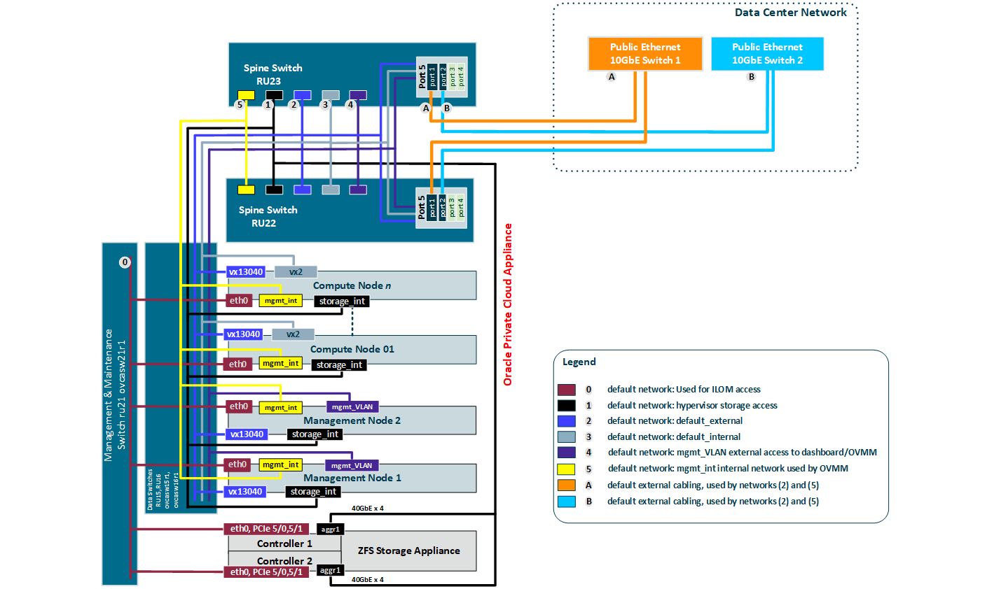
C.2.1 External Ethernet Connections
This section shows the external Ethernet connectivity of an Oracle Private Cloud Appliance using the Cisco Nexus 9336C-FX2 Switch.
C.2.2 Compute Node Networking
This section shows how Oracle Private Cloud Appliance networking is virtualized and configured on a compute node.
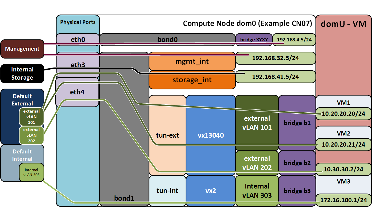
Diagram Notes
-
vx13040 is the default external network.
-
Internal and External vLAN IDs are specified when creating the network in Oracle VM Manager
-
IP addresses in the 10.0/8 range used here are examples. The actual IP addresses are assigned in the VMs themselves.
-
storage-int is a network for hypervisor access to the storage nodes
-
The virtual networks connecting the network bonds numbered 0-4 are configured by default on every Oracle Private Cloud Appliance. The network connecting all
bond6interfaces is an example of a custom private VM network. The network connecting allbond5interfaces is an example of a custom public VM network. This type of network requires the configuration of additional I/O ports, which must also be cabled to the next-level data center switches for public access.
C.2.3 Management Node Networking
This section shows how Oracle Private Cloud Appliance networking is virtualized and configured on the management nodes.
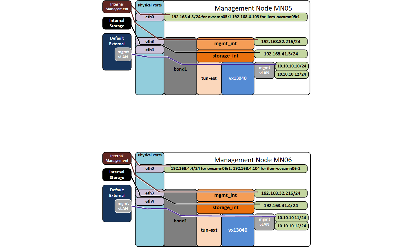
Diagram Notes
-
10.10.10.10/24 is the external address of management node 05
-
10.10.10.11/24 is the external address of management node 06
-
10.10.10.12 is the external address of the VIP for management
-
External addresses of mgmt vLAN are specified in the PCA dashboard and are used for access to the PCA Dashboard and OVMM for managing the PCA.
-
storage-int is an underlay network for hypervisor access to the storage nodes