Chapter 2 Monitoring and Managing Oracle Private Cloud Appliance
- 2.1 Connecting and Logging in to the Oracle Private Cloud Appliance Dashboard
- 2.2 Oracle Private Cloud Appliance Accessibility Features
- 2.3 Hardware View
- 2.4 Network Settings
- 2.5 Functional Networking Limitations
- 2.6 Network Customization
- 2.7 VM Storage Networks
- 2.8 Tenant Groups
- 2.9 Authentication
- 2.10 Health Monitoring
- 2.11 Fault Monitoring
- 2.12 Cloud Backup
-
2.13 Kubernetes Engine
- 2.13.1 Kubernetes Guidelines and Limitations
- 2.13.2 Prepare the Cluster Environment
- 2.13.3 Create a Kubernetes Cluster on a DHCP Network
- 2.13.4 Create a Kubernetes Cluster on a Static Network
- 2.13.5 Use the Kubernetes Dashboard
- 2.13.6 Managing a Cluster
- 2.13.7 Stop a Cluster
- 2.13.8 Monitor Cluster Status
- 2.13.9 Resize Kubernetes Virtual Machine Disk Space
- 2.13.10 Maintain the Operating Systems on the Kubernetes Virtual Machines
Monitoring and management of the Oracle Private Cloud Appliance is achieved using the Oracle Private Cloud Appliance Dashboard. This web-based graphical user interface is also used to perform the initial configuration of the appliance beyond the instructions provided in the Quick Start poster included in the packaging of the appliance.
Before starting the system and applying the initial configuration, read and understand the Oracle Private Cloud Appliance Release Notes. The section Known Limitations and Workarounds provides information that is critical for correctly executing the procedures in this document. Ignoring the release notes may cause you to configure the system incorrectly. Bringing the system back to normal operation may require a complete factory reset.
The Oracle Private Cloud Appliance Dashboard allows you to perform the following tasks:
-
Initial software configuration (and reconfiguration) for the appliance using the Network Environment window, as described in Section 2.4, “Network Settings”.
-
Hardware provisioning monitoring and identification of each hardware component used in the appliance, accessed via the Hardware View window described in Section 2.3, “Hardware View”.
-
Resetting the passwords used for different components within the appliance, via the Password Management window, as described in Section 2.9, “Authentication”.
The Oracle Private Cloud Appliance Controller Software includes functionality that is currently not available through the Dashboard user interface:
-
Backup
The configuration of all components within Oracle Private Cloud Appliance is automatically backed up based on a crontab entry. This functionality is not configurable. Restoring a backup requires the intervention of an Oracle-qualified service person. For details, see Section 1.6, “Oracle Private Cloud Appliance Backup”.
-
Update
The update process is controlled from the command line of the active management node, using the Oracle Private Cloud Appliance Upgrader. For details, see Section 1.7, “Oracle Private Cloud Appliance Upgrader”. For step-by-step instructions, see Chapter 3, Updating Oracle Private Cloud Appliance.
-
Custom Networks
In situations where the default network configuration is not sufficient, the command line interface allows you to create additional networks at the appliance level. For details and step-by-step instructions, see Section 2.6, “Network Customization”.
-
Tenant Groups
The command line interface provides commands to optionally subdivide an Oracle Private Cloud Appliance environment into a number of isolated groups of compute nodes. These groups of servers are called tenant groups, which are reflected in Oracle VM as different server pools. For details and step-by-step instructions, see Section 2.8, “Tenant Groups”.
2.1 Connecting and Logging in to the Oracle Private Cloud Appliance Dashboard
To open the Login page of the Oracle Private Cloud Appliance Dashboard, enter the following address in a Web browser:
https://manager-vip:7002/dashboard
Where, manager-vip refers to the shared
Virtual IP address that you have configured for your management
nodes during installation. By using the shared Virtual IP address,
you ensure that you always access the Oracle Private Cloud Appliance Dashboard
on the active management node.
If you are following the installation process and this is your first time accessing the
Oracle Private Cloud Appliance Dashboard, the Virtual IP address in use by the active management node is
set to the factory default 192.168.4.216 . This is an IP
address in the internal appliance management network, which can only be reached if you use a
workstation patched directly into the available Ethernet port 48 in the Cisco Nexus 9348GC-FXP Switch.
Systems with an InfiniBand-based network architecture contain a pair Oracle Switch ES1-24 switches instead. If your appliance contains such switches, connected the workstation to Ethernet port 19 in one of them, not both.
The default user name is admin and the default password is Welcome1. For security reasons, you must set a new password at your earliest convenience.
You must ensure that if you are accessing the Oracle Private Cloud Appliance Dashboard through a firewalled connection, the firewall is configured to allow TCP traffic on the port that the Oracle Private Cloud Appliance Dashboard is using to listen for connections.
Enter your Oracle Private Cloud Appliance Dashboard administration user name in the User Name field. This is the administration user name you configured during installation. Enter the password for the Oracle Private Cloud Appliance Dashboard administration user name in the Password field.
The Oracle Private Cloud Appliance Dashboard makes use of cookies in order to store session data. Therefore, to successfully log in and use the Oracle Private Cloud Appliance Dashboard, your web browser must accept cookies from the Oracle Private Cloud Appliance Dashboard host.
When you have logged in to the Dashboard successfully, the home page is displayed. The central part of the page contains Quick Launch buttons that provide direct access to the key functional areas.

From every Dashboard window you can always go to any other window by clicking the Menu in the top-left corner and selecting a different window from the list. A button in the header area allows you to open Oracle VM Manager.
2.2 Oracle Private Cloud Appliance Accessibility Features
For detailed accessibility information, refer to the chapter Documentation Accessibility in the Oracle Private Cloud Appliance Release Notes.
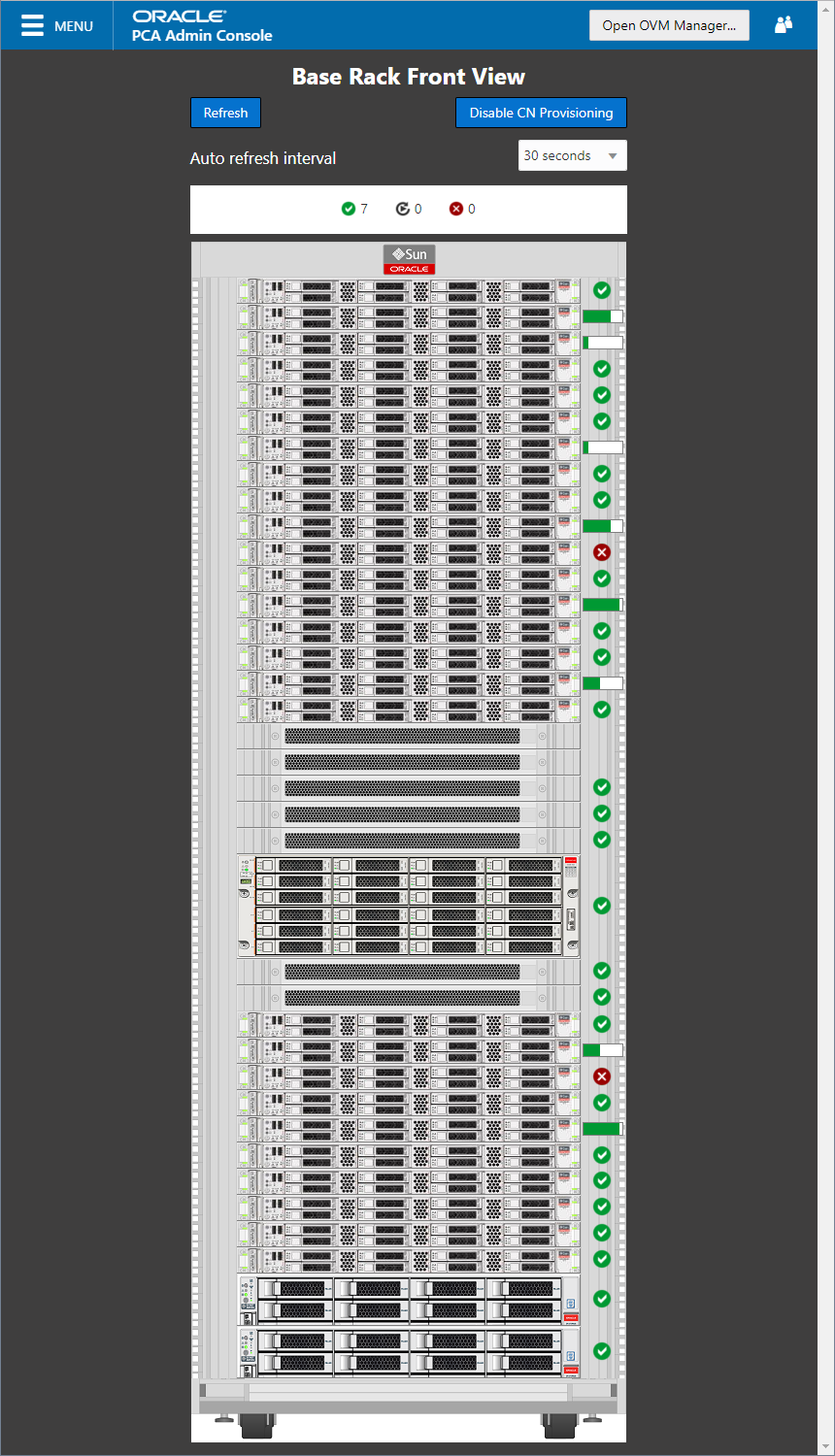
2.3 Hardware View
The Hardware View window within the Oracle Private Cloud Appliance Dashboard provides a graphical representation of the hardware components as they are installed within the rack. The view of the status of these components is automatically refreshed every 30 seconds by default. You can set the refresh interval or disable it through the Auto Refresh Interval list. Alternatively, a button at the top of the page allows you to refresh the view at any time.
During particular maintenance tasks, such as upgrading management nodes, you may need to disable compute node provisioning temporarily. This button at the top of the page allows you to suspend provisioning activity. When compute node provisioning is suspended, the button text changes to and its purpose changes to allow you to resume compute node provisioning as required.
Rolling over each item in the graphic with the mouse raises a pop-up window providing the name of the component, its type, and a summary of configuration and status information. For compute nodes, the pop-up window includes a button, which allows you to restart the provisioning process if the node becomes stuck in an intermittent state or goes into error status before it is added to the Oracle VM server pool. Instructions to reprovision a compute node are provided in Section 7.10, “Reprovisioning a Compute Node when Provisioning Fails”.
The button is to be used only for compute nodes that fail to complete provisioning. For compute nodes that have been provisioned properly and/or host running virtual machines, the button is made unavailable to prevent incorrect use, thus protecting healthy compute nodes from loss of functionality, data corruption, or being locked out of the environment permanently.
Reprovisioning restores a compute node to a clean state. If a compute node was previously added to the Oracle VM environment and has active connections to storage repositories other than those on the internal ZFS storage, the external storage connections need to be configured again after reprovisioning.
Alongside each installed component within the appliance rack, a status icon provides an indication of the provisioning status of the component. A status summary is displayed just above the rack image, indicating with icons and numbers how many nodes have been provisioned, are being provisioned, or are in error status. The Hardware View does not provide real-time health and status information about active components. Its monitoring functionality is restricted to the provisioning process. When a component has been provisioned completely and correctly, the Hardware View continues to indicate correct operation even if the component should fail or be powered off. See Table 2.1 for an overview of the different status icons and their meaning.
|
Icon |
Status |
Description |
|---|---|---|
|

|
OK |
The component is running correctly and has passed all health check operations. Provisioning is complete. |
|

|
Provisioning |
The component is running, and provisioning is in progress. The progress bar fills up as the component goes through the various stages of provisioning. Key stages for compute nodes include: HMP initialization actions, Oracle VM Server installation, network configuration, storage setup, and server pool membership. |
|

|
Error |
The component is not running and has failed health check operations. Component troubleshooting is required and the component may need to be replaced. Compute nodes also have this status when provisioning has failed. |
For real-time health and status information of your active Oracle Private Cloud Appliance hardware, after provisioning, consult the Oracle VM Manager or Oracle Enterprise Manager UI.
The Hardware View provides an accessible tool for troubleshooting hardware components within the Oracle Private Cloud Appliance and identifying where these components are actually located within the rack. Where components might need replacing, the new component must take the position of the old component within the rack to maintain configuration.
2.4 Network Settings
The Network Environment window is used to configure networking and service information for the management nodes. For this purpose, you should reserve three IP addresses in the public (data center) network: one for each management node, and one to be used as virtual IP address by both management nodes. The virtual IP address provides access to the Dashboard once the software initialization is complete.
To avoid network interference and conflicts, you must ensure that the data center network does not overlap with any of the infrastructure subnets of the Oracle Private Cloud Appliance default configuration. These are the subnets and VLANs you should keep clear:
Subnets:
-
192.168.4.0/24 – internal machine administration network: connects ILOMs and physical hosts
-
192.168.140.0/24 – internal Oracle VM management network: connects Oracle VM Manager, Oracle VM Server and Oracle VM Agents (applies only to the InfiniBand-based architecture)
-
192.168.32.0/21 – internal management network: traffic between management and compute nodes
-
192.168.64.0/21 – underlay network for east/west traffic within the appliance environment
-
192.168.72.0/21 – underlay network for north/south traffic, enabling external connectivity
-
192.168.40.0/21 – storage network: traffic between the servers and the ZFS storage appliance
Each /21 subnet comprises the IP ranges of
eight /24 subnets or over 2000 IP addresses.
For example: 192.168.32.0/21 corresponds with
all IP addresses from 192.168.32.1 to
192.168.39.255.
VLANs:
-
1 – the Cisco default VLAN
-
3040 – the default service VLAN
-
3041-3072 – a range of 31 VLANs reserved for customer VM and host networks
-
3073-3099 – a range reserved for system-level connectivity
NoteVLANs 3090-3093 are already in use for tagged traffic over the
/21subnets listed above. -
3968-4095 – a range reserved for Cisco internal device allocation
The Network Environment window is divided into three tabs: Management Nodes, Data Center Network, and DNS. Each tab is shown in this section, along with a description of the available configuration fields.
You can undo the changes you made in any of the tabs by clicking the Reset button. To confirm the configuration changes you made, enter the Dashboard Admin user password in the applicable field at the bottom of the window, and click Apply Changes.
When you click Apply Changes, the configuration settings in all three tabs are applied. Make sure that all required fields in all tabs contain valid information before you proceed.
Figure 2.4 shows the Management Nodes tab. The following fields are available for configuration:
-
Management Node 1:
-
IP Address: Specify an IP address within your datacenter network that can be used to directly access this management node.
-
Host Name: Specify the host name for the first management node system.
-
-
Management Node 2:
-
IP Address: Specify an IP address within your datacenter network that can be used to directly access this management node.
-
Host Name: Specify the host name for the second management node system.
-
-
Management Virtual IP Address: Specify the shared Virtual IP address that is used to always access the active management node. This IP address must be in the same subnet as the IP addresses that you have specified for each management node.
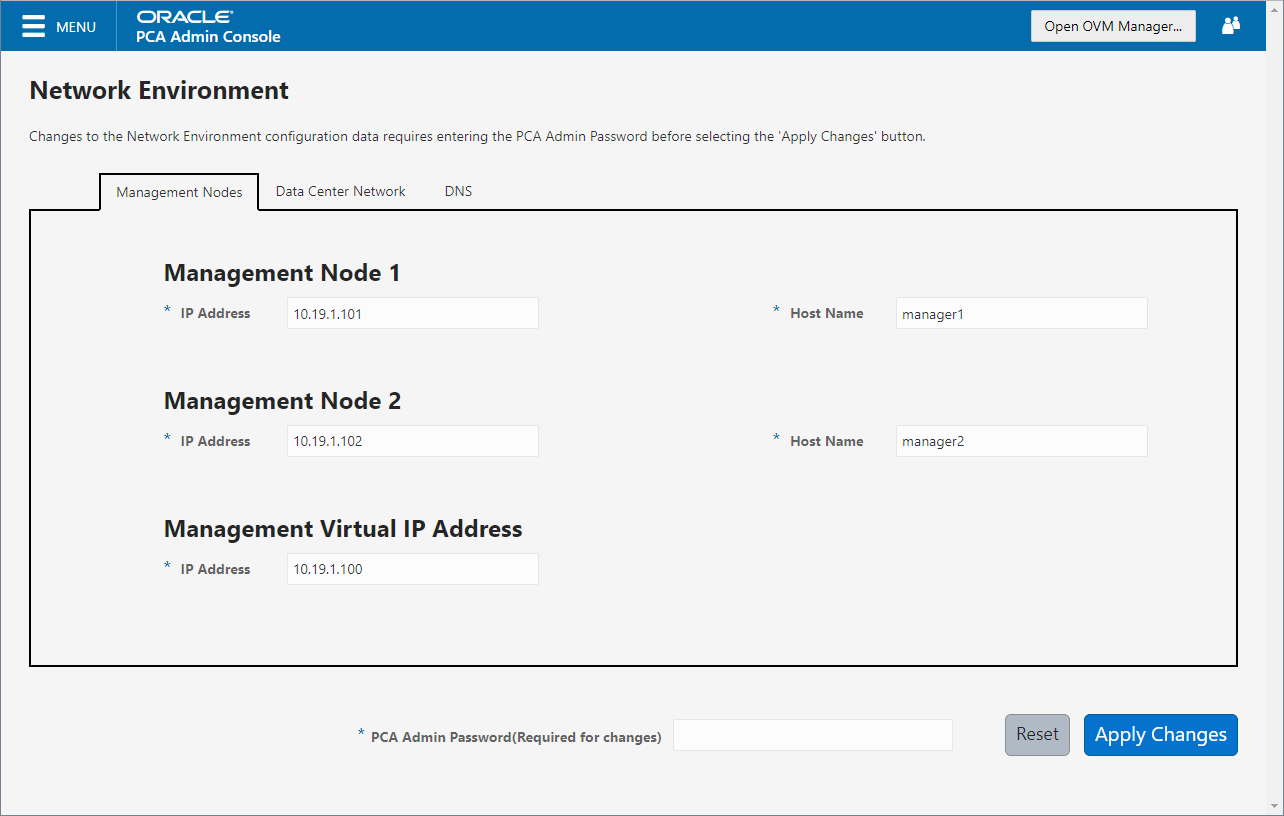
Figure 2.5 shows the Data Center Network tab. The following fields are available for configuration:
-
Management Network VLAN: The default configuration does not assume that your management network exists on a VLAN. If you have configured a VLAN on your switch for the management network, you should toggle the slider to the active setting and then specify the VLAN ID in the provided field.
CautionFor systems with Ethernet-based network architecture, a management VLAN requires additional configuration steps.
When a VLAN is used for the management network, and VM traffic must be enabled over the same network, you must manually configure a VLAN interface on the vx13040 interfaces of the necessary compute nodes to connect them to the VLAN with the ID in question. For instructions to create a VLAN interface on a compute node, refer to the Create a VLAN section in the Oracle VM documentation.
-
Domain Name: Specify the data center domain that the management nodes belong to.
-
Netmask: Specify the netmask for the network that the Virtual IP address and management node IP addresses belong to.
-
Default Gateway: Specify the default gateway for the network that the Virtual IP address and management node IP addresses belong to.
-
NTP: Specify the NTP server that the management nodes and other appliance components must use to synchronize their clocks to.
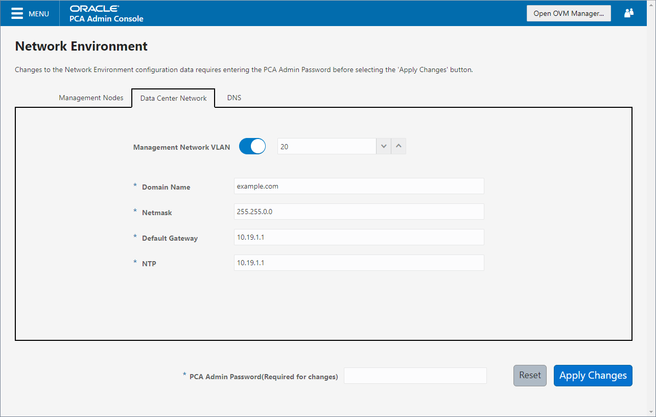
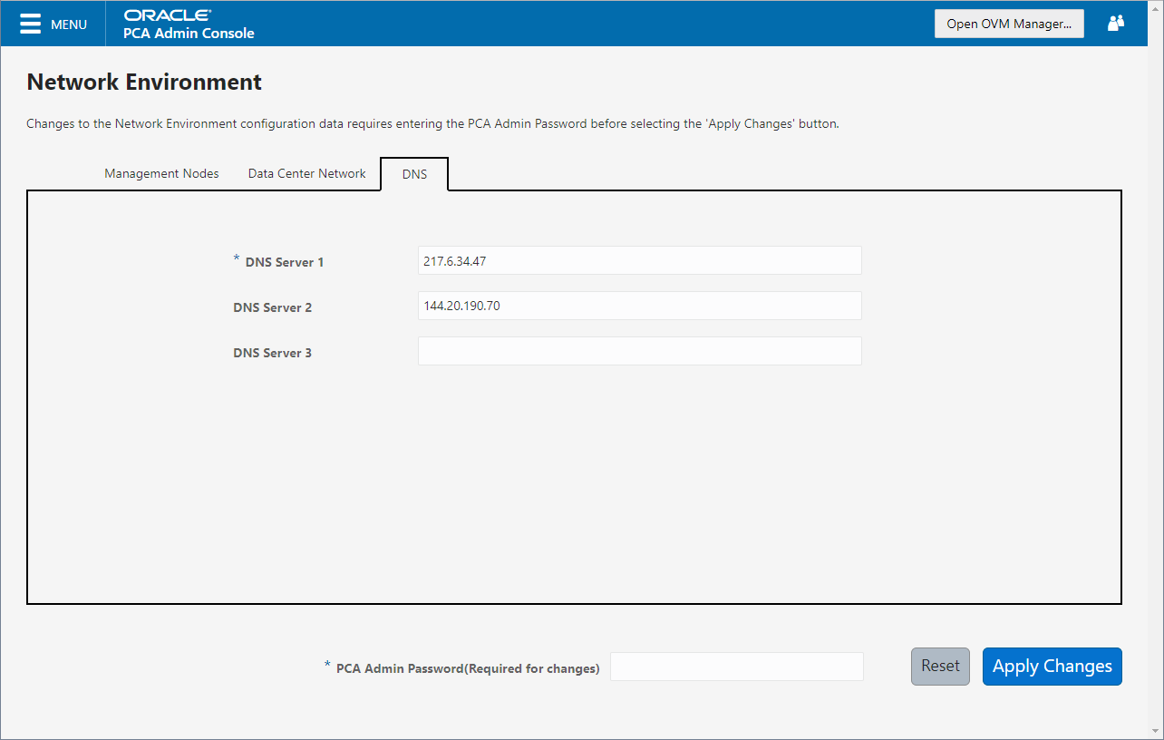
Figure 2.6 shows the Data Center Network tab. The following fields are available for configuration:
-
DNS Server 1: Specify at least one DNS server that the management nodes can use for domain name resolution.
-
DNS Server 2: Optionally, specify a second DNS server.
-
DNS Server 3: Optionally, specify a third DNS server.
You must enter the current Oracle Private Cloud Appliance
Admin account password to make changes to any
of these settings. Clicking the button at the bottom of the page saves the
settings that are currently filled out in all three Network
Environment tabs, and updates the configuration on each of the
management nodes. The ovca services are
restarted in the process, so you are required to log back in to
the Dashboard afterwards.
2.5 Functional Networking Limitations
There are different levels and areas of network configuration in an Oracle Private Cloud Appliance environment. For the correct operation of both the host infrastructure and the virtualized environment it is critical that the administrator can make a functional distinction between the different categories of networking, and knows how and where to configure all of them. This section is intended as guidance to select the suitable interface to perform the main network administration operations.
In terms of functionality, practically all networks operate either at the appliance level or the virtualization level. Each has its own administrative interface: Oracle Private Cloud Appliance Dashboard and CLI on the one hand, and Oracle VM Manager on the other. However, the network configuration is not as clearly separated, because networking in Oracle VM depends heavily on existing configuration at the infrastructure level. For example, configuring a new public virtual machine network in Oracle VM Manager requires that the hosts or compute nodes have network ports already connected to an underlying network with a gateway to the data center network or internet.
A significant amount of configuration – networking and other – is pushed from the appliance level to Oracle VM during compute node provisioning. This implies that a hierarchy exists; that appliance-level configuration operations must be explored before you consider making changes in Oracle VM Manager beyond the standard virtual machine management.
Network Architecture Differences
Oracle Private Cloud Appliance exists in two different types of network architecture. One is built around a physical InfiniBand fabric; the other relies on physical high speed Ethernet connectivity. While the two implementations offer practically the same functionality, there are visible hardware and configuration differences.
This section is split up by network architecture to avoid confusion. Refer to the subsection that applies to your appliance.
2.5.1 Network Configuration of Ethernet-based Systems
This section describes the Oracle Private Cloud Appliance and Oracle VM network configuration for systems with an Ethernet-based network architecture.
-
Virtual Machine Network
By default, a fully provisioned Oracle Private Cloud Appliance is ready for virtual machine deployment. In Oracle VM Manager you can connect virtual machines to these networks directly:
-
default_external, created on thevx13040VxLAN interfaces of all compute nodes during provisioning -
default_internal, created on thevx2VxLAN interfaces of all compute nodes during provisioning
Also, you can create additional VLAN interfaces and VLANs with the Virtual Machine role. For virtual machines requiring public connectivity, use the compute nodes'
vx13040VxLAN interfaces. For internal-only VM traffic, use thevx2VxLAN interfaces. For details, see Section 5.6, “Configuring Network Resources for Virtual Machines”.NoteDo not create virtual machine networks using the
ethports. These are detected in Oracle VM Manager as physical compute node network interfaces, but they are not cabled. Also, thexbondports and default VLAN interfaces (xtun-ext,tun-int,mgmt-intandstorage-int) that appear in Oracle VM Manager are part of the appliance infrastructure networking, and are not intended to be used in VM network configurations.Virtual machine networking can be further diversified and segregated by means of custom networks, which are described below. Custom networks must be created in the Oracle Private Cloud Appliance CLI. This generates additional VxLAN interfaces equivalent to the default
vx13040andvx2. The custom networks and associated network interfaces are automatically set up in Oracle VM Manager, where you can expand the virtual machine network configuration with those newly discovered network resources. -
-
Custom Network
Custom networks are infrastructure networks you create in addition to the default configuration. These are constructed in the same way as the default private and public networks, but using different compute node network interfaces and terminating on different spine switch ports. Whenever public connectivity is required, additional cabling between the spine switches and the next-level data center switches is required.
Because they are part of the infrastructure underlying Oracle VM, all custom networks must be configured through the Oracle Private Cloud Appliance CLI. The administrator chooses between three types: private, public or host network. For detailed information about the purpose and configuration of each type, see Section 2.6, “Network Customization”.
If your environment has additional tenant groups, which are separate Oracle VM server pools, then a custom network can be associated with one or more tenant groups. This allows you to securely separate traffic belonging to different tenant groups and the virtual machines deployed as part of them. For details, see Section 2.8, “Tenant Groups”.
Once custom networks have been fully configured through the Oracle Private Cloud Appliance CLI, the networks and associated ports automatically appear in Oracle VM Manager. There, additional VLAN interfaces can be configured on top of the new VxLAN interfaces, and then used to create more VLANs for virtual machine connectivity. The host network is a special type of custom public network, which can assume the Storage network role and can be used to connect external storage directly to compute nodes.
-
Network Properties
The network role is a property used within Oracle VM. Most of the networks you configure, have the Virtual Machine role, although you could decide to use a separate network for storage connectivity or virtual machine migration. Network roles – and other properties such as name and description, which interfaces are connected, properties of the interfaces and so on – can be configured in Oracle VM Manager, as long as they do not conflict with properties defined at the appliance level.
Modifying network properties of the VM networks you configured in Oracle VM Manager involves little risk. However, you must not change the configuration – such as network roles, ports and so on – of the default networks: eth_management, mgmt_internal, storage_internal, underlay_external, underlay_internal, default_external, and default_internal. For networks connecting compute nodes, including custom networks, you must use the Oracle Private Cloud Appliance CLI. Furthermore, you cannot modify the functional properties of a custom network: you have to delete it and create a new one with the required properties.
The maximum transfer unit (MTU) of a network interface, standard port or bond, cannot be modified. It is determined by the hardware properties or the SDN configuration, which cannot be controlled from within Oracle VM Manager.
-
VLAN Management
With the exception of the underlay VLAN networks configured through SDN, and the appliance management VLAN you configure in the Network Settings tab of the Oracle Private Cloud Appliance Dashboard, all VLAN configuration and management operations are performed in Oracle VM Manager. These VLANs are part of the VM networking.
TipWhen a large number of VLANs is required, it is good practice not to generate them all at once, because the process is time-consuming. Instead, add (or remove) VLANs in groups of 10.
2.5.2 Network Configuration of InfiniBand-based Systems
This section describes the Oracle Private Cloud Appliance and Oracle VM network configuration for systems with an InfiniBand-based network architecture.
-
Virtual Machine Network
By default, a fully provisioned Oracle Private Cloud Appliance is ready for virtual machine deployment. In Oracle VM Manager you can connect virtual machines to these networks directly:
-
vm_public_vlan, created on thebond4interfaces of all compute nodes during provisioning -
vm_private, created on thebond3interfaces of all compute nodes during provisioning
Also, you can create additional VLAN interfaces and VLANs with the Virtual Machine role. For virtual machines requiring public connectivity, use the compute nodes'
bond4ports. For internal-only VM traffic, use thebond3ports. For details, see Section 5.6, “Configuring Network Resources for Virtual Machines”.NoteDo not create virtual machine networks using the
ethports. These are detected in Oracle VM Manager as physical compute node network interfaces, but they are not cabled. Also, most network interfaces are combined in pairs to form bond ports, and are not intended to be connected individually.xVirtual machine networking can be further diversified and segregated by means of custom networks, which are described below. Custom networks must be created in the Oracle Private Cloud Appliance CLI. This generates additional bond ports equivalent to the default
bond3andbond4. The custom networks and associated bond ports are automatically set up in Oracle VM Manager, where you can expand the virtual machine network configuration with those newly discovered network resources. -
-
Custom Network
Custom networks are infrastructure networks you create in addition to the default configuration. These are constructed in the same way as the default private and public networks, but using different compute node bond ports and terminating on different Fabric Interconnect I/O ports. Whenever public connectivity is required, additional cabling between the I/O ports and the next-level data center switches is required.
Because they are part of the infrastructure underlying Oracle VM, all custom networks must be configured through the Oracle Private Cloud Appliance CLI. The administrator chooses between three types: private, public or host network. For detailed information about the purpose and configuration of each type, see Section 2.6, “Network Customization”.
If your environment has tenant groups, which are separate Oracle VM server pools, then a custom network can be associated with one or more tenant groups. This allows you to securely separate traffic belonging to different tenant groups and the virtual machines deployed as part of them. For details, see Section 2.8, “Tenant Groups”.
Once custom networks have been fully configured through the Oracle Private Cloud Appliance CLI, the networks and associated ports automatically appear in Oracle VM Manager. There, additional VLAN interfaces can be configured on top of the new bond ports, and then used to create more VLANs for virtual machine connectivity. The host network is a special type of custom public network, which can assume the Storage network role and can be used to connect external storage directly to compute nodes.
-
Network Properties
The network role is a property used within Oracle VM. Most of the networks you configure, have the Virtual Machine role, although you could decide to use a separate network for storage connectivity or virtual machine migration. Network roles – and other properties such as name and description, which interfaces are connected, properties of the interfaces and so on – can be configured in Oracle VM Manager, as long as they do not conflict with properties defined at the appliance level.
Modifying network properties of the VM networks you configured in Oracle VM Manager involves little risk. However, you must not change the configuration – such as network roles, ports and so on – of the default networks: mgmt_public_eth, 192.168.140.0, 192.168.40.0, vm_public_vlan and vm_private. For networks connecting compute nodes, including custom networks, you must use the Oracle Private Cloud Appliance CLI. Furthermore, you cannot modify the functional properties of a custom network: you have to delete it and create a new one with the required properties.
The maximum transfer unit (MTU) of a network interface, standard port or bond, cannot be modified. It is determined by the hardware properties or the Fabric Interconnect configuration, which cannot be controlled from within Oracle VM Manager.
-
VLAN Management
With the exception of the appliance management VLAN, which is configured in the Network Settings tab of the Oracle Private Cloud Appliance Dashboard, all VLAN configuration and management operations are performed in Oracle VM Manager. These VLANs are part of the VM networking.
TipWhen a large number of VLANs is required, it is good practice not to generate them all at once, because the process is time-consuming. Instead, add (or remove) VLANs in groups of 10.
2.6 Network Customization
The Oracle Private Cloud Appliance controller software allows you to add custom networks at the appliance level. This means that certain hardware components require configuration changes to enable the additional connectivity. The new networks are then configured automatically in your Oracle VM environment, where they can be used for isolating and optimizing network traffic beyond the capabilities of the default network configuration. All custom networks, both internal and public, are VLAN-capable.
The virtual machines hosted on the Oracle Private Cloud Appliance have access to external compute resources and storage, through the default external facing networks, as soon as the Oracle VM Manager is accessible.
If you need additional network functionality, custom networks can be configured and for virtual machines and compute nodes. For example, a custom network can provide virtual machines with additional bandwidth or additional access to external compute resources or storage. Or you can use a custom network if compute nodes need to access storage repositories and data disks contained on external storage. The sections below describe how to configure and cable your Oracle Private Cloud Appliance for these custom networks.
Do not modify the network configuration while upgrade operations are running. No management operations are supported during upgrade, as these may lead to configuration inconsistencies and significant repair downtime.
Custom networks must never be deleted in Oracle VM Manager. Doing so would leave the environment in an error state that is extremely difficult to repair. To avoid downtime and data loss, always perform custom network operations in the Oracle Private Cloud Appliance CLI.
The following network limitations apply:
-
The maximum number of custom external networks is 7 per tenant group or per compute node.
-
The maximum number of custom internal networks is 3 per tenant group or per compute node.
-
The maximum number of VLANs is 256 per tenant group or per compute node.
-
Only one host network can be assigned per tenant group or per compute node.
When configuring custom networks, make sure that no provisioning operations or virtual machine environment modifications take place. This might lock Oracle VM resources and cause your Oracle Private Cloud Appliance CLI commands to fail.
Creating custom networks requires use of the CLI. The administrator chooses between three types: a network internal to the appliance, a network with external connectivity, or a host network. Custom networks appear automatically in Oracle VM Manager. The internal and external networks take the virtual machine network role, while a host network may have the virtual machine and storage network roles.
The host network is a particular type of external network: its configuration contains additional parameters for subnet and routing. The servers connected to it also receive an IP address in that subnet, and consequently can connect to an external network device. The host network is particularly useful for direct access to storage devices.
Network Architecture Differences
Oracle Private Cloud Appliance exists in two different types of network architecture. One is built around a physical InfiniBand fabric; the other relies on physical high speed Ethernet connectivity. While the two implementations offer practically the same functionality, the configuration of custom networks is different due to the type of network hardware.
This section is split up by network architecture to avoid confusion. Refer to the subsection that applies to your appliance.
2.6.1 Configuring Custom Networks on Ethernet-based Systems
This section describes how to configure custom networks on a system with an Ethernet-based network architecture.
For all networks with external connectivity, the spine Cisco Nexus 9336C-FX2 Switch ports must be specified so that these are reconfigured to route the external traffic. These ports must be cabled to create the physical uplink to the next-level switches in the data center. For detailed information, refer to Appliance Uplink Configuration in the Network Requirements of the Oracle Private Cloud Appliance Installation Guide.
-
Using SSH and an account with superuser privileges, log into the active management node.
NoteThe default
rootpassword is Welcome1. For security reasons, you must set a new password at your earliest convenience.# ssh root@10.100.1.101 root@10.100.1.101's password: root@ovcamn05r1 ~]#
-
Launch the Oracle Private Cloud Appliance command line interface.
# pca-admin Welcome to PCA! Release: 2.4.3 PCA>
-
If your custom network requires public connectivity, you need to use one or more spine switch ports. Verify the number of ports available and carefully plan your network customizations accordingly. The following example shows how to retrieve that information from your system:
PCA> list network-port Port Switch Type State Networks ---- ------ ---- ----- -------- 1:1 ovcasw22r1 10G down None 1:2 ovcasw22r1 10G down None 1:3 ovcasw22r1 10G down None 1:4 ovcasw22r1 10G down None 2 ovcasw22r1 40G up None 3 ovcasw22r1 auto-speed down None 4 ovcasw22r1 auto-speed down None 5:1 ovcasw22r1 10G up default_external 5:2 ovcasw22r1 10G down default_external 5:3 ovcasw22r1 10G down None 5:4 ovcasw22r1 10G down None 1:1 ovcasw23r1 10G down None 1:2 ovcasw23r1 10G down None 1:3 ovcasw23r1 10G down None 1:4 ovcasw23r1 10G down None 2 ovcasw23r1 40G up None 3 ovcasw23r1 auto-speed down None 4 ovcasw23r1 auto-speed down None 5:1 ovcasw23r1 10G up default_external 5:2 ovcasw23r1 10G down default_external 5:3 ovcasw23r1 10G down None 5:4 ovcasw23r1 10G down None ----------------- 22 rows displayed Status: Success
-
For a custom network with external connectivity, configure an uplink port group with the uplink ports you wish to use for this traffic. Select the appropriate breakout mode
PCA> create uplink-port-group
MyUplinkPortGroup'1:1 1:2' 10g-4x Status: SuccessNoteThe port arguments are specified as
'x:y'wherexis the switch port number andyis the number of the breakout port, in case a splitter cable is attached to the switch port. The example above shows how to retrieve that information.You must set the breakout mode of the uplink port group. When a 4-way breakout cable is used, all four ports must be set to either 10Gbit or 25Gbit. When no breakout cable is used, the port speed for the uplink port group should be either 100Gbit or 40Gbit, depending on connectivity requirements. See Section 4.2.18, “create uplink-port-group” for command details.
Network ports can not be part of more than one network configuration.
-
Create a new network and select one of these types:
-
rack_internal_network: an Oracle VM virtual machine network with no access to external networking; no IP addresses are assigned to compute nodes. Use this option to allow virtual machines additional bandwidth beyond the default internal network. -
external_network: an Oracle VM virtual machine network with access to external networking; no IP addresses are assigned to compute nodes. Use this option to allow virtual machines additional bandwidth when accessing external storage on a physical network separate from the default external facing network. -
host_network: an Oracle VM compute node network with access to external networking; IP addresses are added to compute nodes. Use this option to allow compute nodes to access storage and compute resources external to the Oracle Private Cloud Appliance. This can also be used by virtual machines to access external compute resources just likeexternal_network.
Use the following syntax:
-
For an internal-only network, specify a network name.
PCA> create network
MyInternalNetworkrack_internal_network Status: Success -
For an external network, specify a network name and the spine switch port group to be configured for external traffic.
PCA> create network
MyPublicNetworkexternal_networkMyUplinkPortGroupStatus: Success -
For a host network, specify a network name, the spine switch ports to be configured for external traffic, the subnet, and optionally the routing configuration.
PCA> create network
MyHostNetworkhost_networkMyUplinkPortGroup\ 10.10.10 255.255.255.0 10.1.20.0/24 10.10.10.250 Status: SuccessNoteIn this example the additional network and routing arguments for the host network are specified as follows, separated by spaces:
-
10.10.10= subnet prefix -
255.255.255.0= netmask -
10.1.20.0/24= route destination (as subnet or IPv4 address) -
10.10.10.250= route gateway
The subnet prefix and netmask are used to assign IP addresses to servers joining the network. The optional route gateway and destination parameters are used to configure a static route in the server's routing table. The route destination is a single IP address by default, so you must specify a netmask if traffic could be intended for different IP addresses in a subnet.
When you define a host network, it is possible to enter invalid or contradictory values for the Prefix, Netmask and Route_Destination parameters. For example, when you enter a prefix with "0" as the first octet, the system attempts to configure IP addresses on compute node Ethernet interfaces starting with 0. Also, when the netmask part of the route destination you enter is invalid, the network is still created, even though an exception occurs. When such a poorly configured network is in an invalid state, it cannot be reconfigured or deleted with standard commands. If an invalid network configuration is applied, use the
--forceoption to delete the network.Details of the create network command arguments are provided in Section 4.2.12, “create network” in the CLI reference chapter.
CautionNetwork and routing parameters of a host network cannot be modified. To change these settings, delete the custom network and re-create it with updated settings.
-
-
-
Connect the required servers to the new custom network. You must provide the network name and the names of the servers to connect.
PCA> add network
MyPublicNetworkovcacn07r1Status: Success PCA> add networkMyPublicNetworkovcacn08r1Status: Success PCA> add networkMyPublicNetworkovcacn09r1Status: Success -
Verify the configuration of the new custom network.
PCA> show network
MyPublicNetwork---------------------------------------- Network_Name MyPublicNetwork Trunkmode None Description None Ports ['1:1', '1:2'] vNICs None Status ready Network_Type external_network Compute_Nodes ovcacn07r1, ovcacn08r1, ovcacn09r1 Prefix None Netmask None Route Destination None Route Gateway None ---------------------------------------- Status: SuccessAs a result of these commands, a VxLAN interface is configured on each of the servers to connect them to the new custom network. These configuration changes are reflected in the Networking tab and the Servers and VMs tab in Oracle VM Manager.
NoteIf the custom network is a host network, the server is assigned an IP address based on the prefix and netmask parameters of the network configuration, and the final octet of the server's internal management IP address.
For example, if the compute node with internal IP address 192.168.4.9 were connected to the host network used for illustration purposes in this procedure, it would receive the address 10.10.10.9 in the host network.
Figure 2.7 shows a custom network named MyPublicNetwork, which is VLAN-capable and uses the compute node's
vx13041interface.Figure 2.7 Oracle VM Manager View of Custom Network Configuration (Ethernet-based Architecture)
-
To disconnect servers from the custom network use the remove network command.
WarningBefore removing the network connection of a server, make sure that no virtual machines are relying on this network.
When a server is no longer connected to a custom network, make sure that its port configuration is cleaned up in Oracle VM.
PCA> remove network
MyPublicNetworkovcacn09r1************************************************************ WARNING !!! THIS IS A DESTRUCTIVE OPERATION. ************************************************************ Are you sure [y/N]:y Status: Success
2.6.2 Configuring Custom Networks on InfiniBand-based Systems
This section describes how to configure custom networks on a system with an InfiniBand-based network architecture.
For all networks with external connectivity the Fabric Interconnect I/O ports must be specified so that these are reconfigured to route the external traffic. These ports must be cabled to create the physical uplink to the next-level switches in the data center.
-
Using SSH and an account with superuser privileges, log into the active management node.
NoteThe default
rootpassword is Welcome1. For security reasons, you must set a new password at your earliest convenience.# ssh root@10.100.1.101 root@10.100.1.101's password: root@ovcamn05r1 ~]#
-
Launch the Oracle Private Cloud Appliance command line interface.
# pca-admin Welcome to PCA! Release: 2.4.3 PCA>
-
If your custom network requires public connectivity, you need to use one or more Fabric Interconnect ports. Verify the number of I/O modules and ports available and carefully plan your network customizations accordingly. The following example shows how to retrieve that information from your system:
PCA> list network-card --sorted-by Director Slot Director Type State Number_Of_Ports ---- -------- ---- ----- --------------- 3 ovcasw15r1 sanFc2Port8GbLrCardEthIb up 2 18 ovcasw15r1 sanFc2Port8GbLrCardEthIb up 2 16 ovcasw15r1 nwEthernet4Port10GbCardEthIb up 4 5 ovcasw15r1 nwEthernet4Port10GbCardEthIb up 4 17 ovcasw15r1 nwEthernet4Port10GbCardEthIb up 4 4 ovcasw15r1 nwEthernet4Port10GbCardEthIb up 4 16 ovcasw22r1 nwEthernet4Port10GbCardEthIb up 4 5 ovcasw22r1 nwEthernet4Port10GbCardEthIb up 4 18 ovcasw22r1 sanFc2Port8GbLrCardEthIb up 2 17 ovcasw22r1 nwEthernet4Port10GbCardEthIb up 4 4 ovcasw22r1 nwEthernet4Port10GbCardEthIb up 4 3 ovcasw22r1 sanFc2Port8GbLrCardEthIb up 2 ----------------- 12 rows displayed Status: Success PCA> list network-port --filter-column Type --filter nwEthernet* --sorted-by State Port Director Type State Networks ---- -------- ---- ----- -------- 4:4 ovcasw15r1 nwEthernet10GbPort down None 4:3 ovcasw15r1 nwEthernet10GbPort down None 4:2 ovcasw15r1 nwEthernet10GbPort down None 5:4 ovcasw15r1 nwEthernet10GbPort down None 5:3 ovcasw15r1 nwEthernet10GbPort down None 5:2 ovcasw15r1 nwEthernet10GbPort down None 10:4 ovcasw15r1 nwEthernet10GbPort down None 10:3 ovcasw15r1 nwEthernet10GbPort down None 10:2 ovcasw15r1 nwEthernet10GbPort down None 10:1 ovcasw15r1 nwEthernet10GbPort down None 11:4 ovcasw15r1 nwEthernet10GbPort down None 11:3 ovcasw15r1 nwEthernet10GbPort down None 11:2 ovcasw15r1 nwEthernet10GbPort down None 11:1 ovcasw15r1 nwEthernet10GbPort down None 4:4 ovcasw22r1 nwEthernet10GbPort down None 4:3 ovcasw22r1 nwEthernet10GbPort down None 4:2 ovcasw22r1 nwEthernet10GbPort down None 5:4 ovcasw22r1 nwEthernet10GbPort down None 5:3 ovcasw22r1 nwEthernet10GbPort down None 5:2 ovcasw22r1 nwEthernet10GbPort down None 10:4 ovcasw22r1 nwEthernet10GbPort down None 10:3 ovcasw22r1 nwEthernet10GbPort down None 10:1 ovcasw22r1 nwEthernet10GbPort down None 11:3 ovcasw22r1 nwEthernet10GbPort down None 11:2 ovcasw22r1 nwEthernet10GbPort down None 11:1 ovcasw22r1 nwEthernet10GbPort down None 4:1 ovcasw15r1 nwEthernet10GbPort up mgmt_public_eth, vm_public_vlan 5:1 ovcasw15r1 nwEthernet10GbPort up mgmt_public_eth, vm_public_vlan 4:1 ovcasw22r1 nwEthernet10GbPort up mgmt_public_eth, vm_public_vlan 5:1 ovcasw22r1 nwEthernet10GbPort up mgmt_public_eth, vm_public_vlan 10:2 ovcasw22r1 nwEthernet10GbPort up None 11:4 ovcasw22r1 nwEthernet10GbPort up None ----------------- 32 rows displayed Status: Success -
Create a new network and select one of these types:
-
rack_internal_network: an Oracle VM virtual machine network with no access to external networking; no IP addresses are assigned to compute nodes. Use this option to allow virtual machines additional bandwidth beyond the default internal network. -
external_network: an Oracle VM virtual machine network with access to external networking; no IP addresses are assigned to compute nodes. Use this option to allow virtual machines additional bandwidth when accessing external storage on a physical network separate from the default external facing network. -
host_network: an Oracle VM compute node network with access to external networking; IP addresses are added to compute nodes. Use this option to allow compute nodes to access storage and compute resources external to the Oracle Private Cloud Appliance. This can also be used by virtual machines to access external compute resources just likeexternal_network.
Use the following syntax:
-
For an internal-only network, specify a network name.
PCA> create network
MyInternalNetworkrack_internal_network Status: Success -
For an external network, specify a network name and the Fabric Interconnect port(s) to be configured for external traffic.
PCA> create network
MyPublicNetworkexternal_network '4:2 5:2' Status: SuccessNoteThe port arguments are specified as
'x:y'wherexis the I/O module slot number andyis the number of the port on that module. The example above shows how to retrieve that information.I/O ports can not be part of more than one network configuration.
If, instead of using the CLI interactive mode, you create a network in a single CLI command from the Oracle Linux prompt, you must escape the quotation marks to prevent bash from interpreting them. Add a backslash character before each quotation mark:
# pca-admin create network
MyPublicNetworkexternal_network \'4:2 5:2\' -
For a host network, specify a network name, the Fabric Interconnect ports to be configured for external traffic, the subnet, and optionally the routing configuration.
PCA> create network
MyHostNetworkhost_network '10:1 11:1' \ 10.10.10 255.255.255.0 10.1.20.0/24 10.10.10.250 Status: SuccessNoteIn this example the additional network and routing arguments for the host network are specified as follows, separated by spaces:
-
10.10.10= subnet prefix -
255.255.255.0= netmask -
10.1.20.0/24= route destination (as subnet or IPv4 address) -
10.10.10.250= route gateway
The subnet prefix and netmask are used to assign IP addresses to servers joining the network. The optional route gateway and destination parameters are used to configure a static route in the server's routing table. The route destination is a single IP address by default, so you must specify a netmask if traffic could be intended for different IP addresses in a subnet.
When you define a host network, it is possible to enter invalid or contradictory values for the Prefix, Netmask and Route_Destination parameters. For example, when you enter a prefix with "0" as the first octet, the system attempts to configure IP addresses on compute node Ethernet interfaces starting with 0. Also, when the netmask part of the route destination you enter is invalid, the network is still created, even though an exception occurs. When such a poorly configured network is in an invalid state, it cannot be reconfigured or deleted with standard commands. If an invalid network configuration is applied, use the
--forceoption to delete the network.Details of the create network command arguments are provided in Section 4.2.12, “create network” in the CLI reference chapter.
CautionNetwork and routing parameters of a host network cannot be modified. To change these settings, delete the custom network and re-create it with updated settings.
-
-
-
Connect the required servers to the new custom network. You must provide the network name and the names of the servers to connect.
PCA> add network
MyPublicNetworkovcacn07r1Status: Success PCA> add networkMyPublicNetworkovcacn08r1Status: Success PCA> add networkMyPublicNetworkovcacn09r1Status: Success -
Verify the configuration of the new custom network.
PCA> show network
MyPublicNetwork---------------------------------------- Network_Name MyPublicNetwork Trunkmode True Description User defined network Ports ['4:2', '5:2'] vNICs ovcacn09r1-eth8, ovcacn07r1-eth8, ovcacn08r1-eth8 Status ready Network_Type external_network Compute_Nodes ovcacn07r1, ovcacn08r1, ovcacn09r1 Prefix None Netmask None Route Destination None Route Gateway None ---------------------------------------- Status: SuccessAs a result of these commands, a bond of two new vNICs is configured on each of the servers to connect them to the new custom network. These configuration changes are reflected in the Networking tab and the Servers and VMs tab in Oracle VM Manager.
NoteIf the custom network is a host network, the server is assigned an IP address based on the prefix and netmask parameters of the network configuration, and the final octet of the server's internal management IP address.
For example, if the compute node with internal IP address 192.168.4.9 were connected to the host network used for illustration purposes in this procedure, it would receive the address 10.10.10.9 in the host network.
Figure 2.8 shows a custom network named MyPublicNetwork, which is VLAN-enabled and uses the compute node's
bond5interface consisting of Ethernet ports (vNICs)eth8andeth8B.Figure 2.8 Oracle VM Manager View of Custom Network Configuration (InfiniBand-based Architecture)
-
To disconnect servers from the custom network use the remove network command.
WarningBefore removing the network connection of a server, make sure that no virtual machines are relying on this network.
When a server is no longer connected to a custom network, make sure that its port configuration is cleaned up in Oracle VM.
PCA> remove network
MyPublicNetworkovcacn09r1************************************************************ WARNING !!! THIS IS A DESTRUCTIVE OPERATION. ************************************************************ Are you sure [y/N]:y Status: Success
2.6.3 Deleting Custom Networks
This section describes how to delete custom networks. The procedure is the same for systems with an Ethernet-based and InfiniBand-based network architecture.
Before deleting a custom network, make sure that all servers have been disconnected from it first.
-
Using SSH and an account with superuser privileges, log into the active management node.
NoteThe default
rootpassword is Welcome1. For security reasons, you must set a new password at your earliest convenience.# ssh root@10.100.1.101 root@10.100.1.101's password: root@ovcamn05r1 ~]#
-
Launch the Oracle Private Cloud Appliance command line interface.
# pca-admin Welcome to PCA! Release: 2.4.3 PCA>
-
Verify that all servers have been disconnected from the custom network. No vNICs or nodes should appear in the network configuration.
CautionRelated configuration changes in Oracle VM must be cleaned up as well.
NoteThe command output sample below shows a public network configuration on an Ethernet-based system. The configuration of a public network on an InfiniBand-based system looks slightly different.
PCA> show network MyPublicNetwork ---------------------------------------- Network_Name MyPublicNetwork Trunkmode None Description None Ports ['1:1', '1:2'] vNICs None Status ready Network_Type external_network Compute_Nodes None Prefix None Netmask None Route_Destination None Route_Gateway None ----------------------------------------
-
Delete the custom network.
PCA> delete network
MyPublicNetwork************************************************************ WARNING !!! THIS IS A DESTRUCTIVE OPERATION. ************************************************************ Are you sure [y/N]:y Status: SuccessCautionIf a custom network is left in an invalid or error state, and the delete command fails, you may use the
--forceoption and retry.
2.7 VM Storage Networks
Starting with Oracle Private Cloud Appliance Controller Software release 2.4.3 running
on Ethernet-based systems, you can configure private storage networks that grant users access
to the internal ZFS storage appliance from their Oracle VM environment. Oracle Private Cloud Appliance
administrators with root access to the management nodes can create and manage the required
networks and ZFS shares (iSCSI/NFS) using the pca-admin command line
interface. To ensure you can use this functionality, upgrade the storage network as described
in Section 3.4, “Upgrading the Storage Network”.
Oracle Private Cloud Appliance Administrators can create up to sixteen VM storage networks which can be accessed by any virtual machine in any tenant group. End users of virtual machines configure their guest operating system to access one or more of these internal storage networks through NFS or iSCSI once the Oracle Private Cloud Appliance administrator has completed the set up.
The VM storage networks are designed to isolate different business systems or groups of end users from each other. For example, the HR department can use two VM storage networks for their virtual machines, while the payroll department can have three or four VM storage networks of their own. Each VM storage network is assigned a single, private non-routed VXLAN to ensure the network is isolated from other virtual machines owned by different end users. End users cannot gain root access to mange the internal ZFS storage appliance through the VM storage networks.
The ability to define internal storage networks directly for VM is introduced in Oracle Private Cloud Appliance Controller Software release 2.4.3. Refer to Oracle Support Document 2722899.1 for important details before using this feature. Should you have any questions, contact Oracle support.
2.8 Tenant Groups
A standard Oracle Private Cloud Appliance environment built on a full rack configuration contains 25 compute nodes. A tenant group is a logical subset of a single Oracle Private Cloud Appliance environment. Tenant groups provide an optional mechanism for an Oracle Private Cloud Appliance administrator to subdivide the environment in arbitrary ways for manageability and isolation. The tenant group offers a means to isolate compute, network and storage resources per end customer. It also offers isolation from cluster faults.
2.8.1 Design Assumptions and Restrictions
Oracle Private Cloud Appliance supports a maximum of 8 tenant groups. This number includes the default tenant group, which cannot be deleted from the environment, and must always contain at least one compute node. Therefore, a single custom tenant group can contain up to 24 compute nodes, while the default Rack1_ServerPool can contain all 25.
Regardless of tenant group membership, all compute nodes are connected to all of the default Oracle Private Cloud Appliance networks. Custom networks can be assigned to multiple tenant groups. When a compute node joins a tenant group, it is also connected to the custom networks associated with the tenant group. When you remove a compute node from a tenant group, it is disconnected from those custom networks. A synchronization mechanism, built into the tenant group functionality, keeps compute node network connections up to date when tenant group configurations change.
When you reprovision compute nodes, they are automatically removed from their tenant groups, and treated as new servers. Consequently, when a compute node is reprovisioned, or when a new compute node is added to the environment, it is added automatically to Rack1_ServerPool. After successful provisioning you can add the compute node to the appropriate tenant group.
When you create a new tenant group, the system does not create a storage repository for the new tenant group. An administrator must configure the necessary storage resources for virtual machines in Oracle VM Manager. See Section 5.7, “Viewing and Managing Storage Resources”.
2.8.2 Configuring Tenant Groups
The tenant group functionality can be accessed through the Oracle Private Cloud Appliance CLI. With a specific set of commands you manage the tenant groups, their member compute nodes, and the associated custom networks. The CLI initiates a number of Oracle VM operations to set up the server pool, and a synchronization service maintains settings across the members of the tenant group.
Do not modify the tenant group configuration while upgrade operations are running. No management operations are supported during upgrade, as these may lead to configuration inconsistencies and significant repair downtime.
You must not modify the server pool in Oracle VM Manager because this causes inconsistencies in the tenant group configuration and disrupts the operation of the synchronization service and the Oracle Private Cloud Appliance CLI. Only server pool policies may be edited in Oracle VM Manager.
If you inadvertently used Oracle VM Manager to modify a tenant group, see Section 7.14, “Recovering from Tenant Group Configuration Mismatches”.
For detailed information about the Oracle Private Cloud Appliance CLI tenant group commands, see Chapter 4, The Oracle Private Cloud Appliance Command Line Interface (CLI).
The command output samples in this section reflect the network configuration on an Ethernet-based system. The network-related properties of a tenant group look slightly different on an InfiniBand-based system.
-
Using SSH and an account with superuser privileges, log into the active management node.
NoteThe default
rootpassword is Welcome1. For security reasons, you must set a new password at your earliest convenience.# ssh root@10.100.1.101 root@10.100.1.101's password: root@ovcamn05r1 ~]#
-
Launch the Oracle Private Cloud Appliance command line interface.
# pca-admin Welcome to PCA! Release: 2.4.3 PCA>
-
Create the new tenant group.
PCA> create tenant-group
myTenantGroupStatus: Success PCA> show tenant-groupmyTenantGroup---------------------------------------- Name myTenantGroup Default False Tenant_Group_ID 0004fb00000200008154bf592c8ac33b Servers None State ready Tenant_Group_VIP None Tenant_Networks ['storage_internal', 'mgmt_internal', 'underlay_internal', 'underlay_external', 'default_external', 'default_internal'] Pool_Filesystem_ID 3600144f0d04414f400005cf529410003 ---------------------------------------- Status: SuccessThe new tenant group appears in Oracle VM Manager as a new server pool. It has a 12GB server pool file system located on the internal ZFS storage appliance.
-
Add compute nodes to the tenant group.
If a compute node is currently part of another tenant group, it is first removed from that tenant group.
CautionIf the compute node is hosting virtual machines, or if storage repositories are presented to the compute node or its current tenant group, removing a compute node from an existing tenant group will fail . If so, you have to migrate the virtual machines and unpresent the repositories before adding the compute node to a new tenant group.
PCA> add compute-node ovcacn07r1
myTenantGroupStatus: Success PCA> add compute-node ovcacn09r1myTenantGroupStatus: Success -
Add a custom network to the tenant group.
PCA> add network-to-tenant-group
myPublicNetworkmyTenantGroupStatus: SuccessCustom networks can be added to the tenant group as a whole. This command creates synchronization tasks to configure custom networks on each server in the tenant group.
CautionWhile synchronization tasks are running, make sure that no reboot or provisioning operations are started on any of the compute nodes involved in the configuration changes.
-
Verify the configuration of the new tenant group.
PCA> show tenant-group
myTenantGroup---------------------------------------- Name myTenantGroup Default False Tenant_Group_ID 0004fb00000200008154bf592c8ac33b Servers ['ovcacn07r1', 'ovcacn09r1'] State ready Tenant_Group_VIP None Tenant_Networks ['storage_internal', 'mgmt_internal', 'underlay_internal', 'underlay_external', 'default_external', 'default_internal', 'myPublicNetwork'] Pool_Filesystem_ID 3600144f0d04414f400005cf529410003 ---------------------------------------- Status: SuccessThe new tenant group corresponds with an Oracle VM server pool with the same name and has a pool file system. The command output also shows that the servers and custom network were added successfully.
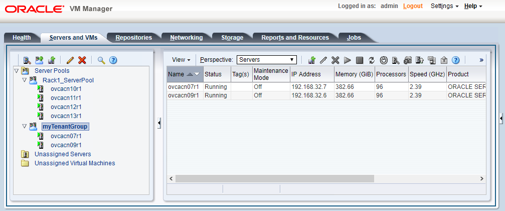
These configuration changes are reflected in the Servers and VMs tab in Oracle VM Manager. Figure 2.9 shows a second server pool named MyTenantGroup, which contains the two compute nodes that were added as examples in the course of this procedure.
The system does not create a storage repository for a new tenant group. An administrator must configure the necessary storage resources for virtual machines in Oracle VM Manager. See Section 5.7, “Viewing and Managing Storage Resources”.
-
Identify the tenant group you intend to modify.
PCA> list tenant-group Name Default State ---- ------- ----- Rack1_ServerPool True ready myTenantGroup False ready ---------------- 2 rows displayed Status: Success PCA> show tenant-group
myTenantGroup---------------------------------------- Name myTenantGroup Default False Tenant_Group_ID 0004fb00000200008154bf592c8ac33b Servers ['ovcacn07r1', 'ovcacn09r1'] State ready Tenant_Group_VIP None Tenant_Networks ['storage_internal', 'mgmt_internal', 'underlay_internal', 'underlay_external', 'default_external', 'default_internal', 'myPublicNetwork'] Pool_Filesystem_ID 3600144f0d04414f400005cf529410003 ---------------------------------------- Status: Success -
Remove a network from the tenant group.
A custom network that has been associated with a tenant group can be removed again. The command results in serial operations, not using the synchronization service, to unconfigure the custom network on each compute node in the tenant group.
PCA> remove network-from-tenant-group
myPublicNetworkmyTenantGroup************************************************************ WARNING !!! THIS IS A DESTRUCTIVE OPERATION. ************************************************************ Are you sure [y/N]:y Status: Success -
Remove a compute node from the tenant group.
Use Oracle VM Manager to prepare the compute node for removal from the tenant group. Make sure that virtual machines have been migrated away from the compute node, and that no storage repositories are presented.
PCA> remove compute-node ovcacn09r1
myTenantGroup************************************************************ WARNING !!! THIS IS A DESTRUCTIVE OPERATION. ************************************************************ Are you sure [y/N]:y Status: SuccessWhen you remove a compute node from a tenant group, any custom network associated with the tenant group is automatically removed from the compute node network configuration. Custom networks that are not associated with the tenant group are not removed.
-
Delete the tenant group.
Before attempting to delete a tenant group, make sure that all compute nodes have been removed.
Before removing the last remaining compute node from the tenant group, use Oracle VM Manager to unpresent any shared repository from the compute node, and then release ownership of it. For more details, refer to the support note with Doc ID 2653515.1
PCA> delete tenant-group myTenantGroup ************************************************************ WARNING !!! THIS IS A DESTRUCTIVE OPERATION. ************************************************************ Are you sure [y/N]:y Status: Success
When the tenant group is deleted, operations are launched to remove the server pool file system LUN from the internal ZFS storage appliance. The tenant group's associated custom networks are not destroyed.
2.9 Authentication
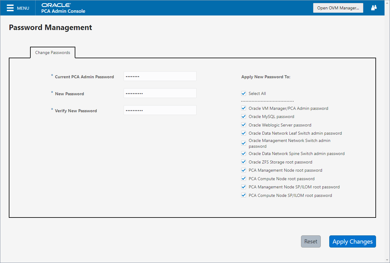
The Password Management window is
used to reset the global Oracle Private Cloud Appliance password and to set
unique passwords for individual components within the appliance.
All actions performed via this tab require that you enter the
current password for the Oracle Private Cloud Appliance admin
user in the field labelled Current
PCA Admin Password:. Fields are available to specify
the new password value and to confirm the value:
-
Current PCA Admin Password: You must provide the current password for the Oracle Private Cloud Appliance
adminuser before any password changes can be applied. -
New Password: Provide the value for the new password that you are setting.
-
Verify Password: Confirm the new password and check that you have not mis-typed what you intended.
The window provides a series of check boxes that make it easy to select the level of granularity that you wish to apply to a password change. By clicking Select All you can apply a global password to all components that are used in the appliance. This action resets any individual passwords that you may have set for particular components. For stricter controls, you may set the password for individual components by simply selecting the check box associated with each component that you wish to apply a password to.
Password changes are not instantaneous across the appliance, but are propagated through a task queue. When applying a password change, allow at least 30 minutes for the change to take effect. Do not attempt any further password changes during this delay. Verify that the password change has been applied correctly.
-
Select All: Apply the new password to all components. All components in the list are selected.
-
Oracle VM Manager/PCA admin password: Set the new password for the Oracle VM Manager and Oracle Private Cloud Appliance Dashboard admin user.
-
Oracle MySQL password: Set the new password for the ovs user in MySQL used by Oracle VM Manager.
-
Oracle WebLogic Server password: Set the new password for the weblogic user in WebLogic Server.
-
Oracle Data Network Leaf Switch admin password: Set the new password for the admin user for the leaf Cisco Nexus 9336C-FX2 Switches.
NoteOn InfiniBand-based systems, the list contains three separate password settings for the data network leaf switches, which are NM2-36P Sun Datacenter InfiniBand Expansion Switches:
-
The Leaf Switch root password check box sets the password for the root user for the NM2-36P Sun Datacenter InfiniBand Expansion Switches.
-
The Leaf Switch ILOM admin password check box sets the password for the admin user for the ILOM of the NM2-36P Sun Datacenter InfiniBand Expansion Switches.
-
The Leaf Switch ILOM operator password check box sets the password for the operator user for the ILOM of the NM2-36P Sun Datacenter InfiniBand Expansion Switches.
-
-
Oracle Management Network Switch admin password: Set the new password for the admin user for the Cisco Nexus 9348GC-FXP Switch.
NoteOn InfiniBand-based systems, this setting applies to the root user for the Oracle Switch ES1-24 switches.
-
Oracle Data Network Spine Switch admin password: Set the new password for the admin user for the spine Cisco Nexus 9336C-FX2 Switches.
NoteOn InfiniBand-based systems, the list contains three separate password settings for the data network spine switches, which are Oracle Fabric Interconnect F1-15 devices:
-
The Spine Switch admin password check box sets the password for the admin user for the Oracle Fabric Interconnect F1-15s.
-
The Spine Switch recovery password sets the password for recovery operations on the Oracle Fabric Interconnect F1-15s. This password is used in the case of a corruption or when the admin password is lost. The Fabric Interconnects can be booted in 'recovery mode' and this password can be used to access the recovery mode menu.
-
The Spine Switch root password check box sets the password for the root user for the Oracle Fabric Interconnect F1-15s.
-
-
Oracle ZFS Storage root password: Set the new password for the root user for the ZFS storage appliance.
-
PCA Management Node root password: Set the new password for the root user for both management nodes.
-
PCA Compute Node root password: Set the new password for the root user for all compute nodes.
-
PCA Management Node SP/ILOM root password: Set the new password for the root user for the ILOM on both management nodes.
-
PCA Compute Node SP/ILOM root password: Set the new password for the root user for the ILOM on all compute nodes.
The functionality that is available in the Oracle Private Cloud Appliance Dashboard is equally available via the Oracle Private Cloud Appliance CLI as described in Section 4.2.56, “update password”.
Passwords of components must not be changed manually as this will cause mismatches with the authentication details stored in the Oracle Private Cloud Appliance Wallet.
2.10 Health Monitoring
The Oracle Private Cloud Appliance Controller Software contains a monitoring
service, which is started and stopped with the
ovca service on the active management node.
When the system runs for the first time it creates an
inventory database and monitor
database. Once these are set up and the monitoring
service is active, health information about the hardware
components is updated continuously.
The inventory database is populated with information about the various components installed in the rack, including the IP addresses to be used for monitoring. With this information, the ping manager pings all known components every 3 minutes and updates the inventory database to indicate whether a component is pingable and when it was last seen online. When errors occur they are logged in the monitor database. Error information is retrieved from the component ILOMs.
For troubleshooting purposes, historic health status details can be retrieved through the CLI support mode by an authorized Oracle Field Engineer. When the CLI is used in support mode, a number of additional commands are available; two of which are used to display the contents of the health monitoring databases.
-
Use
show db inventoryto display component health status information from the inventory database. -
Use
show db monitorto display errors logged in the monitoring database.
The appliance administrator can retrieve current component health status information from the Oracle Linux command line on the active management node, using the Oracle Private Cloud Appliance Health Check utility. The Health Check utility is built on the framework of the Oracle Private Cloud Appliance Upgrader, and is included in the Upgrader package. It detects the appliance network architecture and runs the sets of health checks defined for the system in question.
-
Using SSH and an account with superuser privileges, log in to the active management node.
NoteThe default
rootpassword is Welcome1. For security reasons, you must set a new password at your earliest convenience.# ssh root@10.100.1.101 root@10.100.1.101's password: root@ovcamn05r1 ~]#
-
Launch the Health Check utility.
# pca_healthcheck PCA Rack Type: PCA X8_BASE. Please refer to log file /nfs/shared_storage/pca_upgrader/log/pca_healthcheck_2019_10_04-12.09.45.log for more details.
After detecting the rack type, the utility executes the applicable health checks.
Beginning PCA Health Checks... Check Management Nodes Are Running 1/24 Check Support Packages 2/24 Check PCA DBs Exist 3/24 PCA Config File 4/24 Check Shares Mounted on Management Nodes 5/24 Check PCA Version 6/24 Check Installed Packages 7/24 Check for OpenSSL CVE-2014-0160 - Security Update 8/24 Management Nodes Have IPv6 Disabled 9/24 Check Oracle VM Manager Version 10/24 Oracle VM Manager Default Networks 11/24 Repositories Defined in Oracle VM Manager 12/24 PCA Services 13/24 Oracle VM Server Model 14/24 Network Interfaces on Compute Nodes 15/24 Oracle VM Manager Settings 16/24 Check Network Leaf Switch 17/24 Check Network Spine Switch 18/24 All Compute Nodes Running 19/24 Test for ovs-agent Service on Compute Nodes 20/24 Test for Shares Mounted on Compute Nodes 21/24 Check for bash ELSA-2014-1306 - Security Update 22/24 Check Compute Node's Active Network Interfaces 23/24 Checking for xen OVMSA-2014-0026 - Security Update 24/24 PCA Health Checks completed after 2 minutes
-
When the health checks have been completed, check the report for failures.
Check Management Nodes Are Running Passed Check Support Packages Passed Check PCA DBs Exist Passed PCA Config File Passed Check Shares Mounted on Management Nodes Passed Check PCA Version Passed Check Installed Packages Passed Check for OpenSSL CVE-2014-0160 - Security Update Passed Management Nodes Have IPv6 Disabled Passed Check Oracle VM Manager Version Passed Oracle VM Manager Default Networks Passed Repositories Defined in Oracle VM Manager Passed PCA Services Passed Oracle VM Server Model Passed Network Interfaces on Compute Nodes Passed Oracle VM Manager Settings Passed Check Network Leaf Switch Passed Check Network Spine Switch Failed All Compute Nodes Running Passed Test for ovs-agent Service on Compute Nodes Passed Test for Shares Mounted on Compute Nodes Passed Check for bash ELSA-2014-1306 - Security Update Passed Check Compute Node's Active Network Interfaces Passed Checking for xen OVMSA-2014-0026 - Security Update Passed --------------------------------------------------------------------------- Overall Status Failed --------------------------------------------------------------------------- Please refer to log file /nfs/shared_storage/pca_upgrader/log/pca_healthcheck_2019_10_04-12.09.45.log for more details.
-
If certain checks have resulted in failures, review the log file for additional diagnostic information. Search for text strings such as "error" and "failed".
# grep -inr "failed" /nfs/shared_storage/pca_upgrader/log/pca_healthcheck_2019_10_04-12.09.45.log 726:[2019-10-04 12:10:51 264234] INFO (healthcheck:254) Check Network Spine Switch Failed - 731: Spine Switch ovcasw22r1 North-South Management Network Port-channel check [FAILED] 733: Spine Switch ovcasw22r1 Multicast Route Check [FAILED] 742: Spine Switch ovcasw23r1 North-South Management Network Port-channel check [FAILED] 750:[2019-10-04 12:10:51 264234] ERROR (precheck:148) [Check Network Spine Switch ()] Failed 955:[2019-10-04 12:12:26 264234] INFO (precheck:116) [Check Network Spine Switch ()] Failed # less /nfs/shared_storage/pca_upgrader/log/pca_healthcheck_2019_10_04-12.09.45.log [...] Spine Switch ovcasw22r1 North-South Management Network Port-channel check [FAILED] Spine Switch ovcasw22r1 OSPF Neighbor Check [OK] Spine Switch ovcasw22r1 Multicast Route Check [FAILED] Spine Switch ovcasw22r1 PIM RP Check [OK] Spine Switch ovcasw22r1 NVE Peer Check [OK] Spine Switch ovcasw22r1 Spine Filesystem Check [OK] Spine Switch ovcasw22r1 Hardware Diagnostic Check [OK] [...]
-
Investigate and fix any detected problems. Repeat the health check until the system passes all checks.
2.11 Fault Monitoring
For Oracle Private Cloud Appliance 2.4.3, the existing health
checker becomes a service, started by the
ovca-daemon on the active management node.
Checks can be run manually from the command line, or using
definitions in the scheduler. Depending on the check definition,
the PCA health checker, the Oracle VM health check, and the PCA
pre-upgrade checks can be invoked.
-
pca_healthcheckmonitors the health of system hardware components. For more details, refer to the Health Monitoring. -
ovm_monitormonitors the Oracle VM manger objects and other environment factors. -
pca_upgradermonitors the system during an upgrade.
Health checking can be integrated with ZFS Phone Home service to send reports on a weekly basis to Oracle. The Phone Home function needs to be activated by the customer and requires that the appliance is registered with ASR. No separate installation is required; all functions come with controller software in Oracle Private Cloud Appliance 2.4.3. For configuration information see Section 2.11.2, “Phone Home Service”.
2.11.1 Using Fault Monitoring Checks
The appliance administrator can access current component health status information from
the Oracle Linux command line on the active management node, using the Oracle Private Cloud Appliance Fault
Monitoring utility. The Fault Monitoring utility is included in the ovca
services and can be accessed using the Oracle Private Cloud Appliance command line on the active
management node. In addition, you can schedule checks to run automatically. The utility
detects the appliance network architecture and runs the sets of health checks defined for
that system.
The Fault Monitoring utility provides flexibility in that you can choose to run an individual check, all the check for a particular monitoring service, or all of the checks available.
-
Using SSH and an account with superuser privileges, log in to the active management node.
# ssh root@10.100.1.101
root@10.100.1.101's password:
root@ovcamn05r1 ~]#
-
List available checks.
[root@ovcamn05r1 ~]# pca-faultmonitor --help usage: pca-faultmonitor [-h] [--list_all_monitors][--list_ovm_monitors] [--list_pca_healthcheck_monitors] [--list_pca_upgrader_monitors] [--run_all_monitors] [--run_ovm_monitors] [--run_pca_healthcheck_monitors] [--run_pca_upgrader_monitors][-m MONITOR_LIST] [--print_report] optional arguments: -h, --help show this help message and exit --list_all_monitors List all Fault Monitors(Oracle VM, pca_healthcheck and pca_upgrader) --list_ovm_monitors List Oracle VM Fault Monitors --list_pca_healthcheck_monitors List pca_healthcheck Fault Monitors --list_pca_upgrader_monitors List pca_upgrader Fault Monitors --run_all_monitors Run all Fault Monitors --run_ovm_monitors Run Oracle VM Fault Monitors --run_pca_healthcheck_monitors Run pca_healthcheck Fault Monitors --run_pca_upgrader_monitors Run pca_upgrader Fault Monitors -m MONITOR_LIST Runs a list of Fault Monitors. Each Fault Monitor must be specified with -m option --print_report Prints the report on console None PCA Rack type: hardware_orange Please refer the log file in /var/log/ovca-faultmonitor.log Please look at fault report in /nfs/shared_storage/faultmonitor/20200512/ Note: Reports will not be created for success status[root@ovcamn05r1 faultmonitor]# pca-faultmonitor --list_pca_upgrader_monitors PCA Rack type: hardware_orange Please refer the log file in /var/log/faultmonitor/ovca-faultmonitor.log Please look at fault report in /nfs/shared_storage/faultmonitor/20200221/ Note: Reports will not be created for success status Listing all PCA upgrader faultmonitors check_ib_symbol_errors verify_inventory_cns check_hardware_faults check_server_name validate_image check_available_space check_ovs_version check_ovm_warning_error check_max_paths_iscsi check_serverUpdateConfiguration check_uptime check_ovmm_default_networks check_onf_error verify_password verify_ntp_server verify_no_upstream_proxies check_rpm_db verify_network_config check_custom_multipath check_ovmm check_yum_proxy check_motd verify_ovmm_cache check_keystore_loc check_yum_repo connect_mysql check_os check_multiple_tenant_groups check_osa_disabled check_xsigo_configs verify_ntp_xsigo check_ilom_version check_pca_services check_mysql_desync_passwords check_max_paths_fc check_dir_mounted check_storage_space verify_xms_cards
-
Run the desired checks.
-
Run all checks.
[root@ovcamn05r1 ~]# pca_faultmonitor --run_all_monitors
-
To run a specific check, or a list of specific checks. List one or more checks, preceeded with
-m.[root@ovcamn05r1 ~]# pca_faultmonitor -m event_monitor -m check_storage_space
-
Run checks for a specific monitor.
[root@ovcamn05r1 ~]# pca_faultmonitor --run_pca_upgrader_monitors [root@ovcamn05r1 faultmonitor]# pca_faultmonitor --run_ovm_monitors PCA Rack type: hardware_orange Please refer the log file in /var/log/faultmonitor/ovca-faultmonitor.log Please look at fault report in /nfs/shared_storage/faultmonitor/20200220/ Note: Reports will not be created for success status Beginning OVM Fault monitor checks ... event_monitor 1/13 repository_utilization_monitor 2/13 storage_utilization_monitor 3/13 db_size_monitor 4/13 onf_monitor 5/13 db_backup_monitor 6/13 firewall_monitor 7/13 server_connectivity_monitor 8/13 network_monitor 9/13 port_flapping_monitor 10/13 storage_path_flapping_monitor 11/13 repository_mount_monitor 12/13 server_pool_monitor 13/13 -------------------------------------------------- Fault Monitor Report Summary -------------------------------------------------- OVM_Event_Monitor Success OVM_Repository_Utilization_Monitor Success OVM_Storage_Utilization_Monitor Success DB_Size_Monitor Success ONF_Monitor Success DB_Backup_Monitor Success Firewall_Monitor Success Server_Connectivity_Monitor Success Network_Monitor Warning Port_Flapping_Monitor Success Storage_Path_Flapping_Monitor Success Repository_Mount_Monitor Warning Server_Pool_Monitor Success -------------------------------------------------- Overall Failure -------------------------------------------------- PCA Rack type: hardware_orange Please refer the log file in /var/log/faultmonitor/ovca-faultmonitor.log Please look at fault report in /nfs/shared_storage/faultmonitor/20200220/ Note: Reports will not be created for success status Monitor execution completed after 5 minutes
-
-
If certain checks have resulted in failures, review the console or log file for additional diagnostic information.
-
Investigate and fix any detected problems. Repeat the check until the system passes all checks.
By default, the run_ovm_monitors,
run_pca_healthcheck_monitors, and
run_pca_upgrader_monitors check are
scheduled to run weekly. You can change the frequency of these
checks or add additional indvidual checks to the scheduler.
You must restart the ovca service to
implement any schedule changes.
-
Using SSH and an account with superuser privileges, log in to the active management node.
# ssh root@10.100.1.101 root@10.100.1.101's password: root@ovcamn05r1 ~]#
-
Change the schedule properties in the
ovca-system.conffile.Use the scheduling format described below.
* * * * * command - - - - - | | | | | | | | | –--- day of week (0-7, Sunday= 0 or 7) | | | –----- month (1-12) | | –------- day of month (1-31) | –--------- hour (0-23) –----------- minute (0-59)[root@ovcamn05r1 ~]# cat /var/lib/ovca/ovca-system.conf [faultmonitor] report_path: /nfs/shared_storage/faultmonitor/ report_format: json report_dir_cleanup_days: 10 disabled_check_list: validate_image enable_phonehome: 0 collect_report: 1 [faultmonitor_scheduler] run_ovm_monitors: 0 2 * * * run_pca_healthcheck_monitors: 0 1 * * * run_pca_upgrader_monitors: 0 0 * * * repository_utilization_monitor: 0 */2 * * * check_ovmm_version: */30 * * * *
-
Using SSH and an account with superuser privileges, log in to the active management node.
# ssh root@10.100.1.101 root@10.100.1.101's password: root@ovcamn05r1 ~]#
-
Change the appropriate property in the
ovca-system.conffile.The
report_formatoptions arejson,text, orhtml.[root@ovcamn05r1 ~]# cat /var/lib/ovca/ovca-system.conf [faultmonitor] report_path: /nfs/shared_storage/faultmonitor/ report_format: json report_dir_cleanup_days: 10 disabled_check_list: validate_image enable_phonehome: 1 collect_report: 1
2.11.2 Phone Home Service
The fault management utility is designed so that the management nodes collect fault data reports and copy those reports to the ZFS storage appliance. If you want Oracle Service to monitor these fault reports, you can configure the Phone Home service to push these reports to Oracle on a weekly basis.
Oracle Private Cloud Appliance uses the existing Phone Home service of the ZFS storage appliance.
-
Install ASR on the Oracle Private Cloud Appliance. See How to Install Auto Service Request (ASR) on Private Cloud Appliance (PCA) X8 (Doc ID 2560988.1).
-
Once ASR is installed on your PCA, you must log in to your My Oracle Service account and approve the Oracle Private Cloud Appliance as a new asset. See How To Manage and Approve Pending Oracle Auto Service Request (ASR) Assets In My Oracle Support (Doc ID 1329200.1).
-
Using SSH and an account with superuser privileges, log in to the active management node.
NoteThe default
rootpassword is Welcome1. For security reasons, you must set a new password at your earliest convenience.# ssh root@10.100.1.101 root@10.100.1.101's password: root@ovcamn05r1 ~]#
-
Enable Phone Home in the fault monitoring service by setting the
enable_phonehomeproperty to1in theovca-system.conffile on both management nodes.By default, Phone Home is disabled in Oracle Private Cloud Appliance.
[root@ovcamn05r1 ~]# edit /var/lib/ovca/ovca-system.conf [faultmonitor] report_path: /nfs/shared_storage/faultmonitor/ report_format: json report_dir_cleanup_days: 10 disabled_check_list: validate_image enable_phonehome: 1 collect_report: 1 -
Log in to the ZFS storage appliance browser interface and enable Phone Home. Go to Configuration > Services > Phone Home and click the power icon to bring the service online.
Now your system is configured to send fault reports to Oracle for automated service response.
2.12 Cloud Backup
The Oracle Private Cloud Appliance Cloud Backup service automates the backup of critical components and configuration data to your customer tenancy in Oracle Cloud Infrastructure (OCI). This feature is designed to recover a Oracle Private Cloud Appliance to a running state after a catastrophic event, it is not designed to backup virtual machines, guest operating systems, or applications and data hosted on virtual machines. Backups of customer virtual machines and applications can be managed using Oracle Site Guard. See Doc ID 1959182.1 Oracle VM 3: Getting Started with Disaster Recovery using Oracle Site Guard.
The Cloud Backup service requires an Oracle Cloud Infrastructure cloud tenancy. The service is designed create a snapshot of backup data from the system, store that snapshot on the internal ZFSSA, then push that snapshot to your Oracle Cloud Infrastructure cloud tenancy for remote storage. Once configured the service automatically runs a backup weekly. For resource management reasons, the 10 latest backups are stored locally on the ZFSSA and on your Oracle Cloud Infrastructure tenancy. At this time, contact Oracle Service to restore your Oracle Private Cloud Appliance from an Oracle Cloud Infrastructure cloud backup.
The Cloud Backup service uses the object storage feature of Oracle Cloud Infrastructure to store your Oracle Private Cloud Appliance configuration backup data. With Object Storage, you can safely and securely store or retrieve data directly from the internet or from within the cloud platform. Object Storage is a regional service and is not tied to any specific compute instance. You can access data from anywhere inside or outside the context of the Oracle Cloud Infrastructure, as long you have internet connectivity and can access one of the Object Storage endpoints. For more information about Object Storage, see https://docs.cloud.oracle.com/en-us/iaas/Content/Object/Concepts/objectstorageoverview.htm.
To use the Cloud Backup service with Oracle Private Cloud Appliance releases earlier than 2.4.3, or systems that have been upgrade to release 2.4.3, contact Oracle Service.
For the best experience using the Cloud Backup service, consider these items.
-
Use an Oracle Cloud Infrastructure region that is in the same region as your Oracle Private Cloud Appliance.
-
Very slow network speeds in the customer premise network (<100Mbps) may result in timeouts, espectially when crossing regions.
-
If you experience timeouts, contact Oracle Service.
-
If the connection to the ZFS storage appliance is severed, for example when a management node is rebooted, this could corrupt the Cloud Backup service. See “Cloud Backup Task Hangs When a ZFSSA Takeover is Performed During Backup” in the Oracle Private Cloud Appliance Release Notes.
2.12.1 Configuring the Cloud Backup Service
This section describes how to initally configure the Cloud Backup service, including how to prepare your Oracle Cloud Infrastructure tenancy to receive backups from the Oracle Private Cloud Appliance.
Configuring the Cloud Backup service does three things: creates a location to store your backups on your Oracle Cloud Infrastructure tenancy, activates the script which gathers backup data from the Oracle Private Cloud Appliance, and finally pushes those backups from your Oracle Private Cloud Appliance to your Oracle Cloud Infrastructure tenancy on a weekly basis.
-
Create an object store bucket on your Oracle Cloud Infrastructure tenancy. See the Creating a Bucket section of Putting Data into Object Storage.
NoteTo locate the OCID for a bucket, see Managing Buckets.
Each target must be associated with its own bucket. Perform this operation to set up each target location for your Oracle Private Cloud Appliance backups.
-
Set up the Oracle Private Cloud Appliance Cloud Backup configuration.
-
Using SSH and an account with superuser privileges, log into the active management node.
NoteThe default
rootpassword is Welcome1. For security reasons, you must set a new password at your earliest convenience.# ssh root@10.100.1.101 root@10.100.1.101's password: root@ovcamn05r1 ~]#
-
Launch the Oracle Private Cloud Appliance command line interface.
# pca-admin
Welcome to PCA! Release: 2.4.3
PCA>
-
Create an Oracle Cloud Infrastructure target on your Oracle Private Cloud Appliance that corresponds with the Oracle Cloud Infrastructure object store bucket created in step 1.
This step creates a target on your PCA ZFSSA that sends scheduled backups to an object storage bucket on Oracle Cloud Infrastructure. For more information see Section 4.2.16, “create oci-target”.
PCA> create oci-target <
target name> <target location> <target user> <target bucket> <target tenancy> <keyfile>For example:
PCA> create oci-target
cloud-target-1https://objectstorage.us-oci.com ocid1.user.oc1..oos-test mybucket ocid1.tenancy.oc1..nobody /root/oci_api_key.pem Status: SuccessThe cloud backup is now configured to run weekly.
-
2.12.2 Configuring a Manual Cloud Backup
This section describes how to trigger a manual cloud backup, which can be useful in preparation for a system upgrade.
-
Using SSH and an account with superuser privileges, log into the active management node.
NoteThe default
rootpassword is Welcome1. For security reasons, you must set a new password at your earliest convenience.# ssh root@10.100.1.101 root@10.100.1.101's password: root@ovcamn05r1 ~]#
-
Launch the Oracle Private Cloud Appliance command line interface.
# pca-admin
Welcome to PCA! Release: 2.4.3
PCA>
-
Create the Cloud Backup.
PCA> create oci-backup
oci-target-name1oci-target-name2The create oci-backup job has been submitted. Use "show task < task id>" to monitor the progress. Task_ID Status Progress Start_Time Task_Name ------- ------ -------- ---------- --------- 386c911399b38e RUNNING None 05-29-2020 21:48:24 oci_backup --------------- 1 row displayed Status: SuccessOnly one backup can run at a time. If there is a conflict, you see this error:
Status: Failure Error Message: Error (SYSTEM_002): Cannot invoke API function oci_backup while lock oci_backup is in place.
To resolve this issue, run your manual backup again, once the other backup task is complete.
2.12.3 Deleting Cloud Backups
This section describes how to delete a Cloud Backup, which removes the backup from both the Oracle Private Cloud Appliance and your Oracle Cloud Infrastructure tenancy.
-
Using SSH and an account with superuser privileges, log into the active management node.
NoteThe default
rootpassword is Welcome1. For security reasons, you must set a new password at your earliest convenience.# ssh root@10.100.1.101 root@10.100.1.101's password: root@ovcamn05r1 ~]#
-
Launch the Oracle Private Cloud Appliance command line interface.
# pca-admin
Welcome to PCA! Release: 2.4.3
PCA>
-
Delete the backup.
PCA> delete oci-backup <OVCA/OCI_backups@AK00000000_OCI_snap_2020_06_29-04.56.28 > WARNING !!! THIS IS A DESTRUCTIVE OPERATION. Are you sure [y/N]:y
2.12.4 Deleting Oracle Cloud InfrastructureTargets
This section describes how to remove an Oracle Cloud Infrastructure target from your Oracle Private Cloud Appliance. The related object store buckets in your Oracle Cloud Infrastructure tenancy are not removed, this operation simply removes the selected target on your PCA, thus breaking the link to that target in your Oracle Cloud Infrastructure tenancy.
-
Using SSH and an account with superuser privileges, log into the active management node.
NoteThe default
rootpassword is Welcome1. For security reasons, you must set a new password at your earliest convenience.# ssh root@10.100.1.101 root@10.100.1.101's password: root@ovcamn05r1 ~]#
-
Launch the Oracle Private Cloud Appliance command line interface.
# pca-admin
Welcome to PCA! Release: 2.4.3
PCA>
-
Delete the Oracle Cloud Infrastructure target on your Oracle Private Cloud Appliance.
PCA> delete oci-target <
target>
2.13 Kubernetes Engine
- 2.13.1 Kubernetes Guidelines and Limitations
- 2.13.2 Prepare the Cluster Environment
- 2.13.3 Create a Kubernetes Cluster on a DHCP Network
- 2.13.4 Create a Kubernetes Cluster on a Static Network
- 2.13.5 Use the Kubernetes Dashboard
- 2.13.6 Managing a Cluster
- 2.13.7 Stop a Cluster
- 2.13.8 Monitor Cluster Status
- 2.13.9 Resize Kubernetes Virtual Machine Disk Space
- 2.13.10 Maintain the Operating Systems on the Kubernetes Virtual Machines
This feature is no longer supported. Kubernetes functions are now available through Oracle Cloud Native Environment.
The Kubernetes Engine for Oracle Private Cloud Appliance automates the provisioning of Oracle VM infrastructure and Kubernetes components to provide an integrated solution for Oracle Private Cloud Appliance. Oracle Private Cloud Appliance administrators define and build Kubernetes clusters and later scale them up or down depending on the Kubernetes administrator's needs.
Oracle Private Cloud Appliance easily automates deployment, scaling and management of Kubernetes application containers. To use Kubernetes Engine for Oracle Private Cloud Appliance, follow the steps below.
2.13.1 Kubernetes Guidelines and Limitations
This section describes the guidelines and limitations for Kubernetes on Oracle Private Cloud Appliance.
-
Kubernetes clusters built with the Oracle Private Cloud Appliance service always contain three master nodes and a load balancer.
-
A Kubernetes cluster requires a static, floating, IPv4 address for the load balancer (regardless of whether the virtual machines will use DHCP or static addresses for the cluster nodes).
-
Only IPv4 clusters are supported.
-
If a network with static addresses will be used for the VM external network, the host names used on the virtual machines must be able to be resolved.
-
A maximum of 255 Kubernetes clusters can be created per Oracle Private Cloud Appliance.
-
A maximum of 255 node pools can be created per Kubernetes cluster.
-
All nodes in a node pool must use the same virtual appliance template version. Mixed virtual appliance templates within a cluster are not supported.
-
An Oracle Private Cloud Appliance administrator should understand the Virtual Routing Redundancy Protocol (VRRP) and if it is already in use on the external network that will host their Kubernetes cluster(s) prior to provisioning Kubernetes clusters. For more information, see Virtual Routing Redundancy Protocol.
-
When deprovisioning an Oracle Private Cloud Appliance compute node running a Kubernetes cluster, follow this procedure: Section 7.11, “Deprovisioning and Replacing a Compute Node”
-
A mirrored storage pool is the preferred ZFS configuration for Kubernetes on Oracle Private Cloud Appliance.
-
Perform a manual backup of a Kubernetes cluster configuration after performing any changes (CRUD) on Kubernetes cluster configuration to ensure a consistent backup.
-
The time it takes to start a Kubernetes cluster after defining it can vary widely depending on the size of the Kubernetes cluster and on the usage of Oracle VM management operations during the building of the cluster. If Oracle VM is not heavily used at the same time as the Kubernetes cluster start, a default Kubernetes cluster that builds 3 master nodes and 3 worker nodes takes approximately 45 minutes. For each additional (or for each worker node subtracted), adjust the build time by approximately 5 minutes, depending on Oracle VM management usage and overlapping cluster operations.
Additionally, the more compute nodes there are in an Oracle Private Cloud Appliance, the more time it will take to build a cluster due to the start and stop timing increases as Network/VLAN interfaces are created and added or removed to or from all of the nodes.
2.13.2 Prepare the Cluster Environment
This section describes how to prepare for a cluster environment on your
Oracle Private Cloud Appliance. First, download the Kubernetes Oracle VM Virtual Appliance, then create
the K8s_Private network for Kubernetes, as shown below.
The virtual appliance templates behave much like other virtual appliances in the Oracle VM environment. The Kubernetes virtual appliances require 50 GB of space per virtual machine. Once you download the virtual appliance and add it to one or more Oracle VM repositories, it can be used to build Kubernetes clusters.
The K8s_Private network is required to provide a way for the cluster
to communicate internally. Once configured, the K8s_Private network
should require minimal management.
-
Download the Kubernetes Engine for Oracle Private Cloud Appliance from Oracle Software Delivery Cloud to a reachable http server. Search for "Kubernetes Engine" to locate the file.
TipTo stage a simple http server, see https://docs.python.org/2/library/simplehttpserver.html. For example, change directory to where you downloaded the virtual appliance as issue this command:
python -m SimpleHTTPServer 8000 The URL in the next step will be http://<your client IP address>:8000/<the downloaded filename> -------------------------------
Enter this URL in the next step:
http://<your-client-IP-address>:8000/<the-downloaded-filename>
-
From the Oracle VM Manager Repositories tab, select the desired repository, then choose Virtual Appliances.
-
Click Import Virtual Appliances then:
-
Enter the URL for the virtual appliance you just downloaded.
The Kubernetes Oracle VM Virtual Appliance is here: (input URL)
-
Enter the hostname or IP address of the proxy server.
-
-
If Oracle VM changed the name of the virtual appliance (it may have appended characters), rename it back to
pca-k8s-1-0-0.ova. -
Repeat for each repository where you want to build Kubernetes cluster nodes.
K8s_Private Network-
Using SSH and an account with superuser privileges, log into the active management node.
NoteThe default
rootpassword is Welcome1. For security reasons, you must set a new password at your earliest convenience.# ssh root@10.100.1.101 root@10.100.1.101's password: root@ovcamn05r1 ~]#
-
Launch the Oracle Private Cloud Appliance command line interface.
# pca-admin
Welcome to PCA! Release: 2.4.3
PCA>
-
Create the private network. Specify the name of the internal network to be used by the
K8s_Privatenetwork.PCA> create network K8S_Private rack_internal_network
-
Add the private network to each tenant groups that will be used for Kubernetes clusters.
PCA> add network-to-tenant-group K8S_Private
tenant_group1NoteDepending upon the number of compute nodes available in Oracle Private Cloud Appliance, the
add network-to-tenant-groupcommand may take 10 or more minutes. You should perform cluster creation only after theK8S_Privatenetwork is assigned to all compute nodes. -
Verify the network was created.
PCA> list network
2.13.3 Create a Kubernetes Cluster on a DHCP Network
This section describes how to create a Kubernetes cluster definition on a DHCP network with the default 3 master nodes and 3 worker nodes. For command reference information, see Section 4.2.14, “create kube-cluster”.
-
From the Oracle Private Cloud Appliance command line interface, specify a name for the cluster, a server pool, an external network, the load balancer IP address (a static IPv4 address), the storage repository, and optionally a virtual appliance name.
PCA> create kube-cluster cluster-1 Rack1_ServerPool vm_public_vlan load_balancer_ipaddress Rack1-Repository
Kubernetes cluster configuration (cluster-1) created
Status: Success
Notevm_public_vlanor any external network you use for your cluster must be up and reachable to successfully create a cluster. This network must be assigned to all compute nodes in the storage pool you use, otherwise clusters will not start. -
Verify the cluster definition was created correctly.
PCA> show kube-cluster cluster-1

----------------------------------------
Cluster              cluster-1
Tenant_Group         Rack1_ServerPool
Tenant_Group_ID      0004fb000020000001398d8312a2bc3b
State                CONFIGURED
Sub_State            VALID
Ops_Required         None
Load_Balancer        100.80.151.119
External_Network     vm_public_vlan
External_Network_ID  1096679b1e
Repository           Rack1-Repository
Repository_ID        0004fb000030000005398d83dd67126791
Assembly             PCA_K8s_va.ova
Assembly_ID          11af134854_PCA_K8s_OVM_OL71
Masters              3
Workers              3
----------------------------------------

Status: Success
-
To add worker nodes to the cluster definition, specify the cluster name, and the quantity of nodes in the worker pool, or the names of the nodes in the worker pool. See Section 4.2.49, “set kube-worker-pool”.
-
Start the cluster. This step builds the cluster from the cluster configuration you just created. Depending on the size of the cluster definition this process can take from 30 minutes to hours. A master node pool is defined with 3 master nodes and cannot be changed. However worker nodes may be added to the DHCP cluster definition.
PCA> start kube-cluster cluster-1
-
Follow the progress of the build using the
show kube-clustercommand.PCA> show kube-cluster cluster-1 ---------------------------------------- Cluster cluster-1 Tenant_Group Rack1_ServerPool Tenant_Group_ID 0004fb000020000001398d8312a2bc3b State AVAILABLE Sub_State None Ops_Required None Load_Balancer 172.16.0.157 Vrrp_ID 236 External_Network default_external Cluster_Network_Type dhcp Gateway None Netmask None Name_Servers None Search_Domains None Repository Rack2-Repository Assembly PCA_K8s_va.ova Masters 3 Workers 3 Cluster_Start_Time 2020-06-14 06:11:32.765239 Cluster_Stop_Time None Job_ID None Job_State None Error_Code None Error_Message None ---------------------------------------- Status: Success
For more information on cluster states, see Section 4.2.52, “start kube-cluster”.
-
Once the cluster is started, collect the node pool information for the cluster.
Save this information, you will use it to hand the clusters off to Kubernetes later.
PCA>  list node-pool --filter-column=Cluster --filter=cluster-1

Cluster     Node_Pool     Tenant_Group     CPUs   Memory   Nodes
-------     ---------     ------------     ----   ------   -----
cluster-1   master        Rack1_ServerPool  4      16384    3
cluster-1   worker        Rack1_ServerPool  2      8192     2

----------------
2 rows displayed

Status: Success
-
Once the cluster is in the AVAILABLE state, consider performing a manual backup to capture the new cluster state. See Section 4.2.8, “backup”.
2.13.4 Create a Kubernetes Cluster on a Static Network
This section describes how to create a Kubernetes cluster with 3 master notes and 1 worker node on a static network.
-
From the Oracle Private Cloud Appliance command line interface, specify a name for the cluster, a server pool, an external network, the load balancer IP address, the storage repository, and optionally a virtual appliance.
PCA> create kube-cluster cluster-2 Rack1_ServerPool default_external load-balancer_ipaddress Rack1-Repository
Kubernetes cluster configuration (cluster-2) created
Status: Success
-
Set the network type to static for the cluster. Specify the cluster name, network type, netmask, and gateway. See Section 4.2.47, “set kube-network”.
NoteThe network you use for your cluster must be up and reachable to successfully create a cluster. This network must be assigned to all compute nodes in the storage pool you use, otherwise clusters will not start.
PCA> set kube-network cluster-2 static netmask gateway_IP
-
Set the DNS server for the cluster. Specify the cluster name, DNS name server address(es), and search domains. See Section 4.2.44, “set kube-dns”.
PCA> set kube-dns cluster-2 dns_IP_1,dns_IP_2 mycompany.com
-
Verify the cluster definition was created correctly.
PCA> show kube-cluster cluster-2
----------------------------------------
Cluster              Static
Tenant_Group         Rack1_ServerPool
State                AVAILABLE
Sub_State            None
Ops_Required         None
Load_Balancer        172.16.0.220
Vrrp_ID              152
External_Network     default_external
Cluster_Network_Type static
Gateway              172.16.0.1
Netmask              255.254.0.0
Name_Servers         144.20.190.70
Search_Domains       ie.company.com,us.voip.companyus.com
Repository           Rack1-Repository
Assembly             OVM_OL7U7_x86_64_PVHVM.ova
Masters              0
Workers              0
Cluster_Start_Time   2020-07-06 23:53:17.717562
Cluster_Stop_Time    None
Job_ID               None
Job_State            None
Error_Code           None
Error_Message        None
----------------------------------------
Status: Success
-
To add worker nodes to the cluster definition, specify the cluster name, then list the names of the nodes you want in the worker pool. See Section 4.2.49, “set kube-worker-pool”.
PCA> set kube-worker-pool cluster-2 worker-node-vm7 worker-node-vm8 worker-node9
-
To add the master pool to the cluster definition, specify the cluster name, list the primary master node with its name and IP address, then list the names of the other nodes you want in the master pool. See Section 4.2.46, “set kube-master-pool”.
PCA> set kube-master-pool demo-cluster cluster-master-0,192.168.0.10 cluster-master-1 cluster-master-2
-
Start the cluster. This step builds the cluster from the cluster configuration you just created. Depending on the size of the cluster definition this process can take from 30 minutes to several hours.
PCA> start kube-cluster cluster-2

Status: Success
-
Follow the progress of the build using the
show kube-clustercommand.PCA> show kube-cluster cluster-2 <need example>
For more information on cluster states, see Section 4.2.52, “start kube-cluster”.
-
Once the cluster is started, collect the node pool information for the cluster.
Save this information, you will use it to hand the clusters off to Kubernetes later.
PCA>  list node-pool --filter-column=Cluster --filter=cluster-2

Cluster     Node_Pool     Tenant_Group     CPUs   Memory   Nodes
-------     ---------     ------------     ----   ------   -----
cluster-2   master        Rack1_ServerPool  4      16384    3
cluster-2   worker        Rack1_ServerPool  2      8192     2

----------------
2 rows displayed

Status: Success
-
Consider performing a manual backup to capture the new cluster state. See Section 4.2.8, “backup”.
2.13.5 Use the Kubernetes Dashboard
This section describes how to use the Kubernetes dashboard that is deployed with your Kubernetes
cluster during the start kube-cluster operation.
-
Install
kubectlon your local machine. You do not need to be root user for this task.Follow the directions to Install and Set Up kubectl from kubernetes.io.
-
Create the .
kubesubdirectory on your local machine.# mkdir -p $HOME/.kube
-
Copy the cluster configuration from the master to your local machine.
# scp root@<
load-balancer-ip>:~/.kube/config ~/.kube/config -
Set your Kubernetes configuration file location.
# export KUBECONFIG=~/.kube/config
-
Confirm the nodes in the cluster are up and running.
# kubectl get nodes
-
Create default user roles for the Kubernetes dashboard, using
dashboard-rbac.yaml.# kubectl apply -f dashboard-rbac.yaml
NoteThere are multiple ways to create user roles to access the Kubernetes dashboard. The following example is one way to do so. Use a method that is most appropriate for your Kubernetes environment.
Example 2.1 Example of Possible dashboard-rbac.yaml File for Account Access to the Kubernetes DashboardapiVersion: v1 kind: ServiceAccount metadata: name: admin-user namespace: kubernetes-dashboard --- apiVersion: rbac.authorization.k8s.io/v1 kind: ClusterRoleBinding metadata: name: admin-user roleRef: apiGroup: rbac.authorization.k8s.io kind: ClusterRole name: cluster-admin subjects: - kind: ServiceAccount name: admin-user namespace: kubernetes-dashboard
For more information on the Kubernetes dashboard, see https://docs.oracle.com/en/operating-systems/olcne/orchestration/dashboard.html.
NoteYou can ignore the Deploying the Dashboard UI step; the Dashboard UI is deployed by default on Oracle Private Cloud Appliance.
For more information on
kubectl, see https://docs.oracle.com/en/operating-systems/olcne/orchestration/kubectl-setup-master.html. -
Once an account is created, get a login token for the Kubernetes dashboard.
This example shows creating a login token for the user account
admin-user, as cited in the example above.kubectl -n kubernetes-dashboard describe secret $(kubectl -n kubernetes-dashboard get secret | grep admin-user | awk '{print $1}')Follow the Getting a Bearer Token directions at the Kubernetes dashboard github site.
-
Start the proxy on your host.
# kubectl proxy
-
Open the Kubernetes dashboard.
http://localhost:8001/api/v1/namespaces/kubernetes-dashboard/services/https:kubernetes-dashboard:/proxy/#/login
You should see your cluster in the dashboard. Now a Kubernetes administrator can manage the cluster through the dashboard just as you would any other Kubernetes cluster. For more information see Oracle Linux Cloud Native Container Orchestration documentation.
If needed, you can configure internet access for worker nodes. This can ease deployment of applications that have dependencies outside of your corporate network.
2.13.6 Managing a Cluster
This section describes some of the common changes you might make to an existing cluster. Once you have made changes to a cluster, perform a manual backup of your Oracle Private Cloud Appliance to save the new configuration. See Section 4.2.8, “backup”.
For information about supporting multiple clusters, refer to https://kubernetes.io/docs/concepts/configuration/organize-cluster-access-kubeconfig/.
|
Task |
Description |
|---|---|
|
Stop a cluster |
PCA> stop kube-cluster
|
|
Add a node pool |
PCA> add node-pool
|
|
Remove a node pool |
PCA> remove node-pool |
|
Add a node pool node |
PCA> add node-pool-node |
|
Remove a node pool node |
PCA> remove node-pool-node |
|
Change the profile of the VMs that are part of the default node pool for masters or workers |
PCA> set kube-vm-shape
|
2.13.7 Stop a Cluster
To stop a cluster, you must empty all nodes from the cluster node pools other than the base master and worker node pools, then delete the extra node pools once they are emptied. This section describes the order to stopping a running cluster, then deleting the configuration information afterward.
Note that the cluster configuration does not have to be deleted after stopping a cluster. The stopped cluster retains information about the master and worker node pools from when the cluster was stopped. Assuming other clusters are not built that would conflict with the addresses in the stopped the cluster, the cluster configuration could be used to start the cluster again with the contents reset to the original state.
Stopping a Kubernetes cluster or node terminates the virtual machines and deletes the system disks. All locally written data and modification on the virtual machine local system disk will be lost.
-
From the Oracle Private Cloud Appliance command line interface, remove the worker nodes.
PCA> remove node-pool-node
MyClusternode-pool-0hostnameRepeat for each worker node in the node pool, until the node pool is empty.
-
Remove the node pool.
PCA> remove node-pool
MyClusternode-pool-0Repeat for each node pool in the cluster, until the cluster is empty.
-
Stop the cluster once the non-master and non-worker node pools are removed.
PCA> stop kube-cluster
MyClusterNotethe
--forceoption can be used on thestop kube-clustercommand. This option attempts to stop all workers regardless of their node pool, remove the node pools (other than master and worker), and leave the cluster in a stopped state. -
Delete the cluster
PCA> delete kube-cluster
MyCluster -
Consider performing a manual backup to capture the new cluster state. See Section 4.2.8, “backup”.
2.13.8 Monitor Cluster Status
There are two parts to a Kubernetes cluster status, the status of the virtual machines used in the Kubernetes cluster, and Kubernetes itself.
-
To monitor the vitrtual machines that host the Kubernetes cluster, get the list of those virtual machines using the Oracle Private Cloud Appliance command line. Once you have the list, log in to Oracle VM to look more deeply at each VM, its run state, and other relevant information.
-
An Oracle Private Cloud Appliance administrator has access to the Oracle VM health, but they do not have access to the Kubernetes runtime health. To view the status of Kubernetes, the Kubernetes administrator should use the Section 2.13.5, “Use the Kubernetes Dashboard” and various
kubectlcommands. See Oveview of kubectl .
2.13.9 Resize Kubernetes Virtual Machine Disk Space
-
Log in to Oracle VM Manager.
For details, see Section 5.2, “Logging in to the Oracle VM Manager Web UI”.
-
Select the Kubernetes virtual machine you wish to change, click Edit, select the Disks tab, and edit the desired disk size.
Figure 2.11 Figure showing Oracle VM Manager resize VM disk screen.
For details, see Edit the Virtual Machine
-
Log in to the Kubernetes virtual machine you just edited and check the amount of disk space.
[root@dhcp1-m-1 ~]# df -kh
Filesystem Size Used Avail Use% Mounted on
devtmpfs 16G 0 16G 0% /dev
tmpfs 16G 0 16G 0% /dev/shm
tmpfs 16G 18M 16G 1% /run
tmpfs 16G 0 16G 0% /sys/fs/cgroup
/dev/xvda3 46G 5.8G 39G 14% /
/dev/xvda1 497M 90M 407M 19% /boot
This example shows increasing the size of
/dev/xvda3from 46G to 496G. -
Run
fdiskto partition the disk space.[root@dhcp1-m-1 ~]# fdisk /dev/xvda Welcome to fdisk (util-linux 2.23.2). Changes will remain in memory only, until you decide to write them. Be careful before using the write command. Command (m for help): d Partition number (1-3, default 3): 3 Partition 3 is deleted Command (m for help): n Partition type: p primary (2 primary, 0 extended, 2 free) e extended Select (default p): p Partition number (3,4, default 3): First sector (9414656-1048575999, default 9414656): Using default value 9414656 Last sector, +sectors or +size{K,M,G} (9414656-1048575999, default 1048575999): Using default value 1048575999 Partition 3 of type Linux and of size 495.5 GiB is set Command (m for help): w The partition table has been altered! Calling ioctl() to re-read partition table. WARNING: Re-reading the partition table failed with error 16: Device or resource busy. The kernel still uses the old table. The new table will be used at the next reboot or after you run partprobe(8) or kpartx(8) Syncing disks. -
Use the
partprobecommand to make the kernel aware of the new partition.[root@dhcp1-m-1 ~]# partprobe
-
Use the
btrfscommand to resize the partition tomax.[root@dhcp1-m-1 ~]# btrfs filesystem resize max / Resize '/' of 'max'
-
Verify the size of the new partition.
[root@dhcp1-m-1 ~]# df -kh
Filesystem Size Used Avail Use% Mounted on
devtmpfs 16G 0 16G 0% /dev
tmpfs 16G 0 16G 0% /dev/shm
tmpfs 16G 18M 16G 1% /run
tmpfs 16G 0 16G 0% /sys/fs/cgroup
/dev/xvda3 496G 5.7G 489G 2% /
/dev/xvda1 497M 90M 407M 19% /boot
2.13.10 Maintain the Operating Systems on the Kubernetes Virtual Machines
When an Oracle Private Cloud Appliance administrator adds worker nodes or re-adds master nodes, the individual node becomes available with the Oracle Linux version, Kubernetes version, and the default settings that were a part of the Kubernetes virtual appliance.
Kubernetes administrators should update the new node(s) with:
-
an updated
rootpassword or changes to use passwordless authorization -
update the proxies that are used by CRI-O to obtain new container images
-
possibly update the Oracle Linux distribution components
Many of these operation can be achieved with efficiency using Ansible playbooks that are applied when a new node is added.
The Kubernetes virtual appliance is based on Oracle Linux 7 Update 8. Administrators can update these images once they are running, keeping in mind new nodes have the original Oracle Linux 7 Update 8 on it.
Because the Kubernetes virtual appliances use Oracle Linux, administrators can follow the instructions at https://docs.oracle.com/en/operating-systems/oracle-linux/7/relnotes7.8/ol7-preface.html to put selected updates on their runtime nodes (such as updating the kernel or individual packages for security updates). Administrators should do as few updates on the runtime nodes as possible and look for Oracle guidance through My Oracle Support notes for specific suggestions for maintaining the Kubernetes virtual appliance.