5 Configuring Oracle Private Cloud Appliance
This chapter explains how to complete the initial configuration of your Oracle Private Cloud Appliance.
First, gather the information you need for the configuration process by completing the Initial Installation Checklist.
Before you connect to the Oracle Private Cloud Appliance for the first time, ensure that you have made the necessary preparations for external network connections. Refer to Network Requirements.
Connect a Workstation to the Appliance
Connect a laptop or workstation to the appliance in order to start system configuration with the initial installation process.
Note:
You access the initial configuration wizard through the Service Web UI using a web browser. For support information, please refer to the Oracle software web browser support policy.
-
Connect a workstation with a web browser directly to the management network using an Ethernet cable connected to port 2 in the management switch.
-
Configure the wired network connection of the workstation to use the static IP address 100.96.3.254/23. You can also add
100.96.1.254/23as another IP address if needed. -
Using the web browser on the workstation, connect to the Oracle Private Cloud Appliance initial configuration interface on the active management node at https://100.96.2.32:30099.
100.96.2.32 is the predefined virtual IP address of the management node cluster for configuring Oracle Private Cloud Appliance.
Complete the Initial Setup
The initial configuration wizard creates an administrator account, binds your system to your Oracle Cloud Infrastructure environment, and configures network connections for your appliance. Once you have completed the initial interview, network and compute services come online, and you can begin to build your cloud.
Complete the Initial Installation Checklist, if you have not already done so.
Caution:
Do not power down the management nodes during the initial configuration process.
-
From the Private Cloud Appliance First Boot page, create the primary administrative account for your appliance, which is used for initial configuration and will persist after the first boot process. Additional accounts can be added later.
- Enter an Administrative Username.
- Enter and confirm the Administrative Password.
Note:
Passwords must contain a minimum of 12 characters with at least one of each: uppercase character, lowercase character, digit, and any punctuation character (expect for double quote ('"') characters, which are not allowed).
- Click Create Account & Login.
Important:
At the Service Enclave Sign In page, Do not sign in and do not refresh your browser.
- Open a terminal to access the Service CLI and
unlock the system.
- Log into one of the management nodes using the primary administrative account details
you just created.
Note:
Management nodes are namedpcamn01,pcamn02andpcamn03by default. You change these names later in the configuration process.$ ssh new-admin-account@pcamn01 -p 30006 Password authentication Password: PCA-ADMIN> - At the
PCA-ADMIN>prompt, entersystemStateunlock. - Verify the system is unlocked.
PCA-ADMIN> show pcaSystem
Command: show pcaSystem
Status: Success
Time: 2022-09-16 12:24:28,232 UTC
Data:
  Id = 5709f72b-c439-4c3a-8959-758df94eff25
  Type = PcaSystem
  System Config State = Config System Params
  system state locked = false
- Close the terminal or type
exit.
- Log into one of the management nodes using the primary administrative account details
you just created.
-
Refresh your web browser to return to the Service Enclave Sign In page and sign in to the system with the primary administrative account.
Note:
You might need to accept the self-signed SSL certificate again before signing in. -
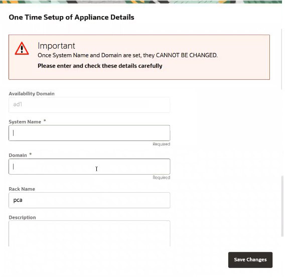
Provide the following appliance details. Required entries are marked with an asterisk.
-
System Name*
-
Domain*
-
Rack Name
-
Description
-
-
Confirm the parameters you just entered are correct. Once System Name and Domain are set, they cannot be changed. Click Save Changes when you are ready to proceed.
-
Refresh your web browser and sign in to the system with the primary administrative account.
Note:
You might need to accept the self-signed SSL certificate again before signing in.The Configure Network Params wizard displays.
- Refer to the information you gathered in the Initial Installation Checklist to complete the system configuration. It is helpful to enter all this information in a text file.
-
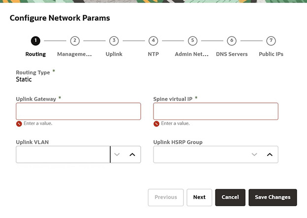
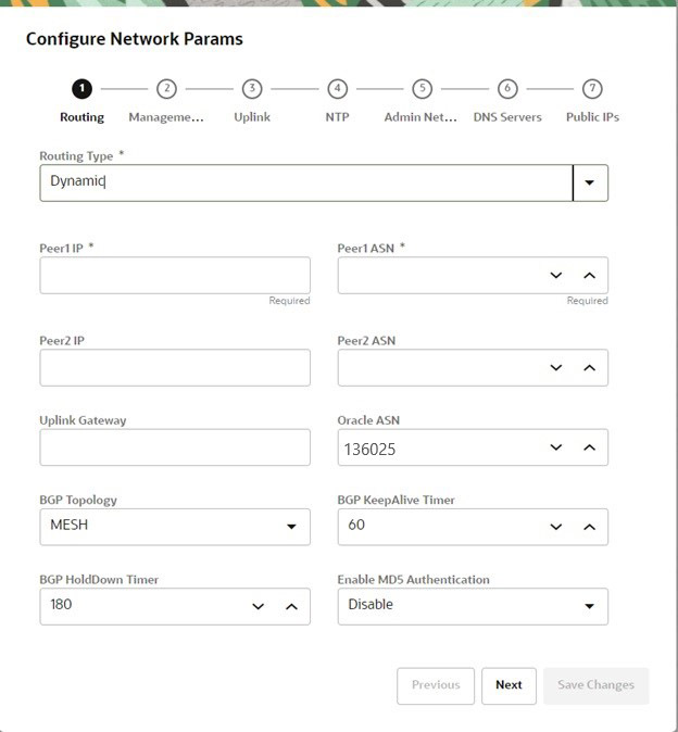
Select either static or dynamic routing.
For static routing configurations
Enter the following data center information, then click Next.
-
Routing Type: Static*
-
Uplink gateway IP Address*
-
Spine virtual IP* (comma-separated values if using the 4 port dynamic mesh topology)
-
Uplink VLAN
-
Uplink HSRP Group
For dynamic configurations
Enter the following data center information, then click Next.
-
Routing Type: Dynamic*
-
Peer1 IP and ASN*
-
Peer2 IP and ASN
-
Uplink Gateway
-
Oracle ASN
-
BGP Topology (square, mesh, triangle), KeepAlive Timer and HoldDown Timer
-
MD5 Authentication: enable or disable
-
-
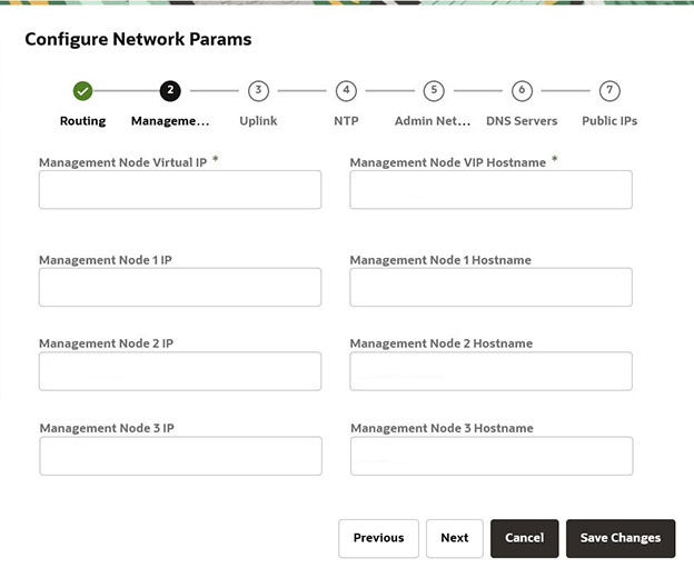
Enter a shared virtual IP and associated host name for the management node cluster; add an IP address and host name for each of the three individual management nodes; and then click Next.
-
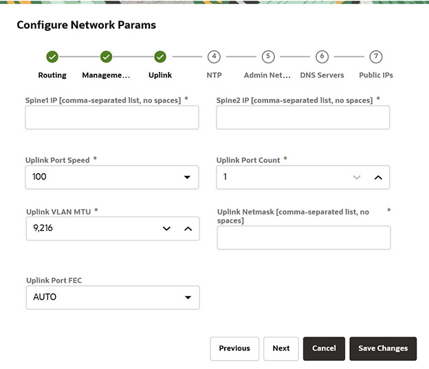
Enter the following data center uplink information and then click Next.
-
IP Address for Spine Switch 1 and 2*
-
Uplink Port Speed and Port Count*
-
Uplink VLAN MTU and Netmask*
-
Uplink Port FEC
-
-
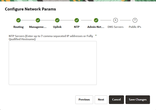
Enter the NTP configuration details and then click Next.
To specify multiple NTP servers, enter a comma separated list of IP addresses or fully qualified host names.
-
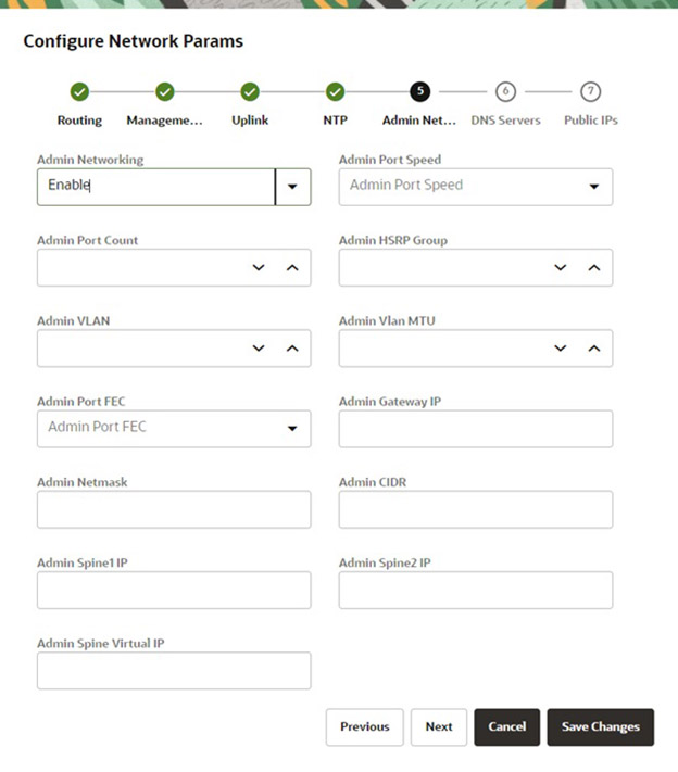
If you elected to segregate administrative appliance access from the data traffic, configure the administration network by entering the following information and then click Next.
-
Enable Admin Networking
-
Admin Port Speed, Port Count, and HSRP Group
-
Admin VLAN, MTU, Port FEC, and Gateway IP
-
Admin Netmask and CIDR
-
Admin IP Address for Spine Switch 1 and 2, and a shared Virtual IP
-
-
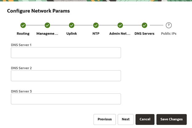
Enter up to three DNS servers in the respective fields and then click Next.
-
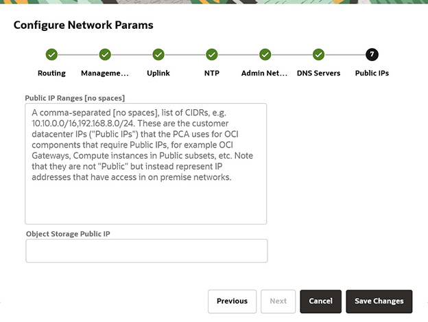
Enter the data center IP addresses that the appliance can assign to resources as public IPs.
-
Public IP list of CIDRs in a comma-separated list
-
Object Storage Public IP (must be outside the public IP range)
-
- Use the Previous/Next buttons to recheck that the information you entered is correct and
then click Save Changes.
Your network configuration information does not persist until you commit your changes in the following step. If you need to change any parameters after testing begins, you must re-enter all information.
Caution:
Once you click Save Changes,network configuration and testing begins and can take up to 15 minutes. Do not close the browser window during this time.If a problem is encountered, the Configure Network Params wizard reopens and the error is displayed.
- At the Testing Network Parameters page, you can re-enter network configuration information
or commit the changes.
- Click Re-enter Network Configuration. You are returned to a blank Configure Network Params wizard where you must enter all your information again.
- Click Commit Changes. The network parameters are locked. Once locked, the routing type and public IPs cannot be changed.
Caution:
Once you click Commit Changes, system initialization begins and can take up to 15 minutes. Do not close the browser window during this time.If a problem is encountered, the Configure Network Params wizard reopens and the error is displayed. Otherwise, a Configuration Complete message displays.
- Click Sign Out. You are returned to the Service Enclave.
-
To continue configuration, connect to the Service Web UI at the new virtual IP address of the management node cluster:
https://<virtual_ip>:30099.Note:
You might need to accept the self-signed SSL certificate again before signing in. -
Verify your system configuration.
- From the Dashboard, click Appliance to view the system details and click Network Environement to view the network configuration.
- Alternatively, you can log in to the Service CLI as an administrator and run the following commands to confirm your
entries.
# ssh 100.96.2.32 -l admin -p 30006
Password:
PCA-ADMIN> show pcaSystem
[...]
PCA-ADMIN> show networkConfig
[...]
For details about the software configuration process, and for advanced configuration and update options, refer to What Next and the Oracle Private Cloud Appliance Administrator Guide.
Configure the Appliance Using the CLI
Using the GUI is the preferred method to perform the initial installation of the Appliance, however, if there is a need to configure the Appliance using the CLI, use the following procedure.
-
Connect a workstation directly to the management network using an Ethernet cable connected to port 2 in the management switch.
-
Configure the wired network connection of the workstation to use the static IP address 100.96.3.254/23.
-
Log in to the Oracle Private Cloud Appliance management node cluster for initial configuration. When prompted for a password, press enter.
# ssh 100.96.2.32 -l "" -p 30006
Password authentication
Password:
100.96.2.32 is the predefined virtual IP address of the management node cluster for configuring Oracle Private Cloud Appliance.
-
Confirm you are logged in as the initial user, where
System Config State = Config User.PCA-ADMIN> show pcaSystem Command: show pcasystem Status: Success Time: 2022-01-20 14:20:01,069 UTC Data: Id = o780c522-fkl5-43b1-8g30-eea90263f2e9 Type = PcaSystem System Config State = Config User
-
Create the primary administrative account for the appliance.
Passwords must contain at least 12 characters with at least one of each: uppercase character, lowercase character, digit, punctuation character, and no doublequote ('"').
PCA-ADMIN> createadminaccount name=admin password=password confirmpassword=password
Command: createadminaccount name=admin password=******** confirmpassword=*******
Status: Success
Time: 2022-01-20 14:23:01,069 UTC
JobId: 302a6h99-fh7y-41sd-8i30-ea28581dcw9e
-
Log out, then log back in with the new credentials you just created.
PCA-ADMIN> exit # ssh new-admin-account@100.96.2.32 -p 30006 Password authentication Password: PCA-ADMIN> -
Confirm the system is ready for configuration, when the
System Config State = Config System Params.PCA-ADMIN> show pcaSystem Command: show pcasystem Status: Success Time: 2022-01-20 14:26:01,069 UTC Data: Id = o780c522-fkl5-43b1-8g30-eea90263f2e9 Type = PcaSystem System Config State = Config System Params […]
-
Configure the system name and domain name, then confirm the settings.
Refer to the information gathered in the Initial Installation Checklist to complete the system configuration.PCA-ADMIN> setDay0SystemParameters systemName=name domainName=us.example.com PCA-ADMIN> show pcasystem Command: show pcasystem Status: Success Time: 2022-01-20 14:26:01,069 UTC Data: Id = o780c522-fkl5-43b1-8g30-eea90263f2e9 Type = PcaSystem […] System Name = name Domain Name = us.example.com Availability Domain = ad1
-
Configure the network parameters. Once you enter these details, network initialization begins and can take up to 15 minutes.
-
For a dynamic network configuration, enter the parameters on a single line.
PCA-ADMIN> setDay0DynamicRoutingParameters \
uplinkPortSpeed=100 \
uplinkPortCount=2 \
uplinkVlanMtu=9216 \
spine1Ip=10.nn.nn.17 \
spine2Ip=10.nn.nn.25 \
uplinkNetmask=255.255.255.252 \
mgmtVipHostname=apac01-vip \
mgmtVip=10.nn.nn.8 \
ntpIps=10.nn.nn.1 \
peer1Asn=50000 \
peer1Ip=10.nn.nn.18 \
peer2ASN=50000 \
peer2Ip=10.nn.nn.22 \
objectStorageIp=10.nn.nn.1
-
For a static network configuration, enter the parameters on a single line.
PCA-ADMIN> setDay0StaticRoutingParameters \
mgmtVip=10.nn.nn.22 \
spine1Ip=10.nn.nn.18 \
spine2Ip=10.nn.nn.19 \
spineVip=10.nn.nn.20 \
uplinkVlan=318\
uplinkNetmask=255.255.252.0 \
uplinkGateway=10.nn.nn.1 \
mgmtVipHostname=plvca5vip \
ntpIps=10.nn.nn.1,10.nn.nn.1 \
objectStorageIp=10.nn.nn.41 \
uplinkHsrpGroup=55 uplinkPortSpeed=100
-
-
Confirm the network parameters are configured. You can monitor the process using the
show NetworkConfigcommand. When the process is complete, theNetwork Config Lifecycyle State = ACTIVE.PCA-ADMIN> show NetworkConfig Command: Success Time: 2022-01-15 14:28:47,781 UTC Data: uplinkPortSpeed=100 uplinkPortCount=2 […] BGP Holddown Timer = 180 Netowrk Config Lifecycle State = ACTIVEWhen this process is complete, theSystem Config Statechanges fromWait for Networking ServicetoConfig_Network_ Params.PCA-ADMIN> show pcasystem Command: show pcasystem Status: Success Time: 2022-01-20 14:29:07,069 UTC Data: Id = o780c522-fkl5-43b1-8g30-eea90263f2e9 Type = PcaSystem System Config State = Config Network Params […]
-
Lock the network parameters.
PCA-ADMIN> lockDay0NetworkParameters
-
Configure the management nodes and DNS servers.
PCA-ADMIN> edit NetworkConfig \
mgmt01Ip=10.nn.nn.9 \
mgmt02Ip=10.nn.nn.10 \
mgmt03Ip=10.nn.nn.11 \
mgmt01Hostname=apac01-mn1 \
mgmt02Hostname=apac01-mn2 \
mgmt03Hostname=apac01-mn3 \
dnsIp1=206.nn.nn.1 \
dnsIp2=206.nn.nn.2 \
dnsIp3=10.nn.nn.197
-
Enter the list of public IPs the appliance can access from your datacenter, in a comma-separated list on one line.
edit NetworkConfig publicIps=10.nn.nn.2/31,10.nn.nn.4/30,10.nn.nn.8/29, \
10.nn.nn.16/28,10.nn.nn.32/27,10.nn.nn.64/26,10.nn.nn.128/26,10.nn.nn.192/27, \
10.nn.nn.224/28,10.nn.nn.240/29,10.nn.nn.248/30,10.nn.nn.252/31,10.nn.nn.254/32
Optional Bastion Host Uplink
In addition to the public Ethernet connection, you may connect the management switch to a management or machine administration network at your installation site. If you choose to use such an uplink, consider it as a long-term alternative to the temporary workstation connection described in Connect a Workstation to the Appliance. Configure the administration uplink after the initialization of the appliance, when the appliance network settings have been applied.
A connection to the appliance internal management network, either directly into the management switch or through an additional Ethernet switch in the data center, is not required to access the appliance management functionality of the Oracle Private Cloud Appliance user interfaces. The primary role of the appliance internal management network is to allow the controller software on the management nodes to interact with the compute nodes and other rack components. Connecting to this network from outside the appliance allows you to gain direct administrator access to each component, for example to control the ILOMs.
Caution:
Do not make any changes to anything on this network unless directed to do so by Oracle Support.
Bastion Host Configuration
Follow these guidelines when configuring a bastion host.
Caution:
Connect port 2 on the management switch.
Make sure that the data center Ethernet switch used in this connection is configured to prevent DHCP leakage to the 100.96.0.0/22 subnet used by Oracle Private Cloud Appliance. Do not connect to any network with any kind of broadcast services in addition to DHCP.
For the bastion host, which is the name used to describe the machine that is permanently connected to the data center administration network, use the IP address 100.96.3.254/23 and assign it statically to its network interface. Make sure there is no other machine on the same subnet using the same IP address and causing IP conflicts.
- Configure two IP addresses on the bastion host.
For example, add 100.96.1.254/23 as a second IP address.
# cat ifcfg-eth1
NAME=eth1
DEVICE=eth1
BOOTPROTO=static
ONBOOT=yes
NM_CONTROLLED=no
USERCTL=no
DEFROUTE=no
IPV6INIT=no
IPADDR1=100.96.3.254
PREFIX1=23
IPADDR2=100.96.1.254
PREFIX2=23
- Or, add a route to the existing networks.
On the 100.96.0.0/23 network, if the bastion host is configured with the IP 100.96.3.254 for subnet 100.96.2.0/23, add this route:
ip route add 100.96.0.0/23 via 100.96.2.1 dev eth1
and on the 100.96.2.0/23 network, if the bastion host is configured with the IP 100.96.1.254 for subnet 100.96.0.0/23, add this route:
ip route add 100.96.2.0/23 via 100.96.0.1 dev eth1
Optional Connection to Exadata
Optionally, Oracle Private Cloud Appliance can be integrated with Oracle Exadata for a high-performance combination of compute capacity and database optimization. In this configuration, database nodes are directly connected to reserved ports on the spine switches of Oracle Private Cloud Appliance. Four 100Gbit ports per spine switch are reserved and split into 4x25Gbit breakout ports, providing a maximum of 32 total cable connections. Each database node is cabled directly to both spine switches, meaning up to 16 database nodes can be connected to the appliance. It is allowed to connect database nodes from different Exadata racks. For more information, see "Exadata Integration" in the Network Infrastructure section of Hardware Overview.
To cable the Oracle Private Cloud Appliance to the Exadata rack use breakout cables, with a QSFP28 transceiver on the spine switch end and four SFP28 transceivers on the other end, to connect from ports 7 - 10 on the Oracle Private Cloud Appliance spine switches to the Exadata database servers.
Reserved Breakout Ports on Spine Switch for Exadata Connection
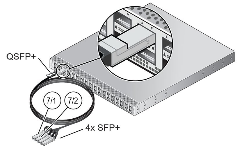
Once the cable connections are in place, you must configure an Exadata network, which enables traffic between the connected database nodes and a set of compute instances. Refer to Creating and Managing Exadata Networks in Hardware Administration.
What Next
Once the initial installation of your Oracle Private Cloud Appliance is complete, you can begin to customize the appliance for use.
Note:
Ensure you provision the compute nodes before you hand off a newly created tenancy to the tenancy administrator. Unprovisioned compute nodes can cause VCN creation to fail.
| Task | Directions | Background Information |
|---|---|---|
|
Configuring ASR |
See "Using Auto Service Requests" in the Status and Health Monitoring section of the Oracle Private Cloud Appliance Administrator Guide. |
See "Using Auto Service Requests" in the Status and Health Monitoring section of the Oracle Private Cloud Appliance Administrator Guide. |
|
Creating a new administrator account |
See "Administrator Account Management" in Oracle Private Cloud Appliance Administrator Guide |
See "Administrator Access" in Appliance Administration Overview |
|
Provision compute nodes |
See "Performing Compute Node Operations" in Hardware Administration |
See "Servers" in Hardware Administration |
|
Create tenancies |
See "Tenancy Management" in Oracle Private Cloud Appliance Administrator Guide |
See "Enclaves and Interfaces" in Architecture and Design |
|
Install the Oracle Cloud Infrastructure CLI in the Compute Enclave |
See "Using the Oracle Cloud Infrastructure CLI" in Working in the Compute Enclave |
See "Enclaves and Interfaces" in Architecture and Design |
|
Create an Internal-Only VNIC and Subnet |
See "Managing VCNs and Subnets" in Networking |
|
|
Create a Network-Accessible VNIC and Subnet |
See "Managing VCNs and Subnets" and "Configuring VCN Gateways" in Networking | See "Virtual Networking Overview" in Networking |
|
Import a compute image |
See "Managing Compute Images" in Compute Instance Deployment |
See "Compute Images" in Compute Instance Provisioning Overview |
|
Launch a compute instance |
See "Tutorial – Launching Your First Linux Instance" in Compute Instance Deployment |
See "Compute Images" in Compute Instance Provisioning Overview |
|
Connect to a compute instance |
See the Connect to Your Instance section of the "Tutorial – Launching Your First Linux Instance" in Compute Instance Deployment |
See "Compute Images" in Compute Instance Provisioning Overview |
|
Get the status of a submitted job |
|