3 SS7 Configuration

Chapter 3, SS7 Configuration, describes the procedures necessary to configure the EAGLE 5 ISS to support the SS7 network.

Introduction

This chapter contains the procedures necessary to configure the EAGLE to support the SS7 network. These items are configured to support the SS7 network.

  • Linksets, including linksets for these features:
    • MTP restart
    • 5-Bit to 8-Bit SLS conversion
    • ITUSLS enhancement
    • Configuring the option for determining how the EAGLE routes messages over restricted linksets and routes - the restricted linkset option.
    • Configuring the options for determining how the EAGLE handles TFC messages from ITU-I and ITU-N networks.
  • Signaling links
  • Routes
  • Level 2 timers
  • Level 3 timers
  • Signaling link test messages
  • The rate that TFA and TFP messages are sent
  • Circular route detection
  • The frequency that signaling-route-set-test (RST) messages are sent for lower priority routes
  • Remote loopback points for the link fault sectionalization feature
  • Options for the TDM Global Timing Interface
  • Changing the high-capacity card temperature alarm thresholds.

Enabling the Large System # Links Controlled Feature

This procedure is used to enable the Large System # Links controlled feature using the feature’s part number and a feature access key.

The feature access key for the Large System # Links controlled feature is based on the feature’s part number and the serial number of the EAGLE, making the feature access key site-specific.

This feature allows the EAGLE to contain a maximum of either 1500, 2000, or 2800 signaling links.

The enable-ctrl-feat command enables the controlled feature by inputting the controlled feature’s access key and the controlled feature’s part number with these parameters:

:fak – The feature access key provided by Oracle. The feature access key contains 13 alphanumeric characters and is not case sensitive.

:partnum – The Oracle-issued part number associated with the signaling link quantity being enabled:

  • 893005901 for the 1500 signaling link quantity
  • 893005910 for the 2000 signaling link quantity.
  • 893005911 for the 2800 signaling link quantity.

The enable-ctrl-feat command requires that the database contain a valid serial number for the EAGLE, and that this serial number is locked. This can be verified with the rtrv-serial-num command. The EAGLE is shipped with a serial number in the database, but the serial number is not locked. The serial number can be changed, if necessary, and locked once the EAGLE is on-site, by using the ent-serial-num command. The ent-serial-num command uses these parameters.

:serial – The serial number assigned to the EAGLE. The serial number is not case sensitive.

:lock – Specifies whether or not the serial number is locked. This parameter has only one value, yes, which locks the serial number. Once the serial number is locked, it cannot be changed.

Note:

To enter and lock the EAGLE’s serial number, the ent-serial-num command must be entered twice, once to add the correct serial number to the database with the serial parameter, then again with the serial and the lock=yes parameters to lock the serial number. You should verify that the serial number in the database is correct before locking the serial number. The serial number can be found on a label affixed to the control shelf (shelf 1100).

This feature cannot be temporarily enabled (with the temporary feature access key).

Once this feature is enabled with the enable-ctrl-feat command, the feature is also activated. The chg-ctrl-feat command is not necessary to activate the feature.

This feature cannot be turned off with the chg-ctrl-feat command and the status=off parameter.

Hardware Supported for Signaling Link Quantities Greater than 2000

This hardware is the only hardware that is supported for an EAGLE containing 2001 to 2800 signaling links.

  • HC-MIM
  • E5-E1/T1
  • E5-ATM
  • E5-SM4G
  • E5-ENET
  • E5-based control cards
  • E5-STC card for the EAGLE 5 Integrated Monitoring Support feature

To increase the signaling link quantity to more than 2000 signaling links, HIPR2 cards must be installed into card locations 9 and 10 in each shelf in the EAGLE. Enter the rept-stat-gpl:gpl=hipr2 command to verify whether or not HIPR2 cards are installed in the EAGLE shelves.

  1. Display the status of the Large System # Links controlled feature by entering the rtrv-ctrl-feat command.

    The following is an example of the possible output.

    
    rlghncxa03w 06-10-28 21:15:37 GMT EAGLE5 36.0.0
    The following features have been permanently enabled:
    
    Feature Name              Partnum    Status  Quantity
    Command Class Management  893005801  on      ----
    LNP Short Message Service 893006601  on      ----
    Intermed GTT Load Sharing 893006901  on      ----
    XGTT Table Expansion      893006101  on      400000
    XMAP Table Expansion      893007710  off     ----
    Routesets                 893006401  on      6000
    HC-MIM SLK Capacity       893012707  on      64
    
    The following features have been temporarily enabled:
    
    Feature Name              Partnum    Status  Quantity     Trial Period Left
    Zero entries found.
    
    The following features have expired temporary keys:
    
    Feature Name              Partnum
    Zero entries found.
    

    If the rtrv-ctrl-feat output shows that the controlled feature is enabled for the desired quantity or for a quantity that is greater than the desired quantity, no further action is necessary. This procedure does not need to be performed.

    If the rtrv-ctrl-feat output in 1 shows any controlled features, or if the Large System # Links controlled feature is enabled for a quantity that is less than the desired quantity, continue the procedure by performing one of these steps.
    • If the enabled quantity will be 1500, continue the procedure with 8.
    • If the enabled quantity will be 2000 or 2800, continue the procedure with 5.

      Note:

      If the rtrv-ctrl-feat output shows only the HC-MIM SLK Capacity feature with a quantity of 64, 2 through 5 must be performed.
  2. Display the serial number in the database with the rtrv-serial-num command.

    This is an example of the possible output.

    
    rlghncxa03w 06-10-28 21:15:37 GMT EAGLE5 36.0.0
    System serial number = nt00001231
    
    System serial number is not locked.
    
    rlghncxa03w 06-10-28 21:15:37 GMT EAGLE5 36.0.0
    Command Completed
    
    If the serial number is correct and locked, continue the procedure by performing one of these steps.
    • If the enabled quantity will be 1500, continue the procedure with 8.
    • If the enabled quantity will be 2000 or 2800, continue the procedure with 6.

    If the serial number is correct but not locked, continue the procedure with 5.

    If the serial number is not correct, but is locked, this feature cannot be enabled and the remainder of this procedure cannot be performed. Contact the Customer Care Center to get an incorrect and locked serial number changed. Refer to My Oracle Support (MOS) for the contact information. The serial number can be found on a label affixed to the control shelf (shelf 1100).

  3. Enter the correct serial number into the database using the ent-serial-num command with the serial parameter.

    For this example, enter this command.

    ent-serial-num:serial=<EAGLE’s correct serial number>

    When this command has successfully completed, the following message should appear.

    
    rlghncxa03w 06-10-28 21:15:37 GMT EAGLE5 36.0.0
    ENT-SERIAL-NUM:  MASP A - COMPLTD
    
  4. Verify that the serial number entered into 3 was entered correctly using the rtrv-serial-num command.

    This is an example of the possible output.

    
    rlghncxa03w 06-10-28 21:15:37 GMT EAGLE5 36.0.0
    System serial number = nt00001231
    
    System serial number is not locked.
    
    rlghncxa03w 06-10-28 21:15:37 GMT EAGLE5 36.0.0
    Command Completed
    

    If the serial number was not entered correctly, repeat 3 and 4 and re-enter the correct serial number.

  5. Lock the serial number in the database by entering the ent-serial-num command with the serial number shown in 2, if the serial number shown in 2 is correct, or with the serial number shown in 4, if the serial number was changed in 3, and with the lock=yes parameter.

    For this example, enter this command.

    ent-serial-num:serial=<EAGLE’s serial number>:lock=yes

    When this command has successfully completed, the following message should appear.

    
    rlghncxa03w 06-10-28 21:15:37 GMT EAGLE5 36.0.0
    ENT-SERIAL-NUM:  MASP A - COMPLTD
    
    Continue the procedure by performing one of these steps.
    • If the enabled quantity will be 1500, continue the procedure with 8.
    • If the enabled quantity will be 2000 or 2800, continue the procedure with 6.
  6. Verify that HIPR2 cards are installed in card locations 9 and 10 in each shelf of the EAGLE. Enter this command.

    rept-stat-gpl:gpl=hipr2

    This is an example of the possible output.

    
    rlghncxa03w 09-07-01 11:40:26 GMT  EAGLE5 41.1.0
    GPL        CARD      RUNNING            APPROVED      TRIAL
    HIPR2      1109      126-002-000        126-002-000   126-003-000
    HIPR2      1110      126-002-000        126-002-000   126-003-000
    HIPR2      1209      126-002-000        126-002-000   126-003-000
    HIPR2      1210      126-002-000        126-002-000   126-003-000
    HIPR2      1309      126-002-000        126-002-000   126-003-000
    HIPR2      1310      126-002-000        126-002-000   126-003-000
    HIPR2      2109      126-002-000        126-002-000   126-003-000
    HIPR2      2110      126-002-000        126-002-000   126-003-000
    Command Completed
    
  7. Before the 2000 or 2800 signaling link quantity can be enabled, make sure the EAGLE is configured with the hardware shown in the “Hardware Supported for Signaling Link Quantities Greater than 2000” section.

    If hardware other than the hardware shown in the “Hardware Supported for Signaling Link Quantities Greater than 2000” section is installed and provisioned, contact the Customer Care Center before enabling the 2000 or 2800 signaling link quantity. Refer to My Oracle Support (MOS) for the contact information.

  8. Enable the Large System # Links controlled feature for the desired quantity with the enable-ctrl-feat command specifying the part number corresponding to the new quantity of signaling links and the feature access key.

    To increase the number of signaling links the EAGLE can contain to 1500, enter this command.

    enable-ctrl-feat:partnum=893005901:fak=<feature access key>

    To increase the number of signaling links the EAGLE can contain to 2000, enter this command.

    enable-ctrl-feat:partnum=893005910:fak=<feature access key>

    To increase the number of signaling links the EAGLE can contain to 2800, enter this command.

    enable-ctrl-feat:partnum=893005911:fak=<feature access key>

    Note:

    A temporary feature access key cannot be specified to enable this feature.

    Note:

    The values for the feature access key (thefak parameter) are provided by Oracle. If you do not have the feature access key for the feature you wish to enable, contact your Sales Representative or Account Representative.

    When the enable-crtl-feat command has successfully completed, this message should appear.

    
    rlghncxa03w 06-10-28 21:15:37 GMT EAGLE5 36.0.0
    ENABLE-CTRL-FEAT: MASP B - COMPLTD
    
  9. Verify the changes by entering the rtrv-ctrl-featcommand with the part number specified in 8.

    If the 1500 signaling link quantity was enabled in 8, enter this command.

    rtrv-ctrl-feat:partnum=893005901

    The following is an example of the possible output.

    
    rlghncxa03w 06-10-28 21:15:37 GMT EAGLE5 36.0.0
    The following features have been permanently enabled:
    
    Feature Name              Partnum    Status  Quantity
    Large System # Links      893005901  on      1500
    
    The following features have been temporarily enabled:
    
    Feature Name              Partnum    Status  Quantity     Trial Period Left
    Zero entries found.
    
    The following features have expired temporary keys:
    
    Feature Name              Partnum
    Zero entries found.
    

    If the 2000 signaling link quantity was enabled in 8, enter this command.

    rtrv-ctrl-feat:partnum=893005910

    The following is an example of the possible output.

    
    rlghncxa03w 06-10-28 21:15:37 GMT EAGLE5 36.0.0
    The following features have been permanently enabled:
    
    Feature Name              Partnum    Status  Quantity
    Large System # Links      893005910  on      2000
    
    The following features have been temporarily enabled:
    
    Feature Name              Partnum    Status  Quantity     Trial Period Left
    Zero entries found.
    
    The following features have expired temporary keys:
    
    Feature Name              Partnum
    Zero entries found.
    

    If the 2800 signaling link quantity was enabled in 8, enter this command.

    rtrv-ctrl-feat:partnum=893005911

    The following is an example of the possible output.

    
    rlghncxa03w 09-07-28 21:15:37 GMT EAGLE5 41.1.0
    The following features have been permanently enabled:
    
    Feature Name              Partnum    Status  Quantity
    Large System # Links      893005911  on      2800
    
    The following features have been temporarily enabled:
    
    Feature Name              Partnum    Status  Quantity     Trial Period Left
    Zero entries found.
    
    The following features have expired temporary keys:
    
    Feature Name              Partnum
    Zero entries found.
    
  10. Back up the new changes using the chg-db:action=backup:dest=fixed command.
    These messages should appear, the active Maintenance and Administration Subsystem Processor (MASP) appears first.
    
    BACKUP (FIXED) : MASP A - Backup starts on active MASP.
    BACKUP (FIXED) : MASP A - Backup on active MASP to fixed disk complete.
    BACKUP (FIXED) : MASP A - Backup starts on standby MASP.
    BACKUP (FIXED) : MASP A - Backup on standby MASP to fixed disk complete.


Sheet 1 of 6


Sheet 2 of 6


Sheet 3 of 6


Sheet 4 of 6


Sheet 5 of 6


Sheet 6 of 6

Adding an SS7 Linkset

This procedure is used to add SS7 linksets to the EAGLE using the ent-ls command and the following parameters shown in Table 3-1.

Table 3-1 Linkset Parameters

lsn

apc/apca/apci/

apcn/apcn24

ppc/ppca/ppci/

ppcn/ppcn24

spc/spca/spci/

spcn/spcn24

apcntype
lst clli sltset l3tset scrn
gwsa gwsm gwsd bei nis
itutfr mtprse slsci asl8 slsrsb
slsocbit multgc gttmode randsls cgttmode

islsrsb

       
The ent-ls command contains other optional parameters that are not used this procedure. These parameters are discussed in more detail in Commands User's Guide or in these sections.
  • The "Configuring a Linkset for the GSM MAP Screening Feature" procedure in Database Administration - Features User's Guide.
  • These procedures in Database Administration - IP7 User's Guide.
    • Configuring an IPGWx Linkset
    • Adding a Mate IPGWx Linkset to another IPGWx Linkset
    • Adding an IPSG M3UA Linkset
    • Adding an IPSG M2PA Linkset

:lsn – The name of the linkset. The linkset name can contain up to 10 characters, with the first character being a letter. However, the SEAS interface supports only eight characters. If this linkset is displayed on the SEAS interface and the linkset name contains more than eight characters, only the first eight characters in the linkset name are shown. If this linkset name contains more than eight characters, and is specified with the linkset commands on the SEAS interface, only the first eight characters can be specified.

:apc/apca/apci/apcn/apcn24 – Adjacent point code – the point code identifying the node that is next to the EAGLE. The adjacent point code can be one of the following types of point codes:
  • :apc/apcaANSI point code
  • :apciITU-I point code, ITU-I spare point code
  • :apcn – 14-bit ITU-N point code, 14-bit ITU-N spare point code
  • :apcn24 – 24-bit ITU-N point code
:ppc/ppca/ppci/ppcn/ppcn24 – Proxy point code used for proxy linksets. Proxy point codes can be used only if a quantity of proxy point codes (shown in the rtrv-ctrl-feat output) is enabled. The proxy point code can be one of the following types of point codes:
  • :ppc/ppcaANSI point code
  • :ppciITU-I point code, ITU-I spare point code
  • :ppcn – 14-bit ITU-N point code, 14-bit ITU-N spare point code
  • :ppcn24 – 24-bit ITU-N point code
:spc/spca/spci/spcn/spcn24 – Secondary point code used for multiple linksets that have the same APC. Secondary point codes can be used only if the Multiple Linksets to Single Adjacent PC feature is enabled and turned on (shown in the rtrv-ctrl-feat output. The secondary point code can be one of the following types of point codes:
  • :spc/spcaANSI point code
  • :spciITU-I point code, ITU-I spare point code
  • :spcn – 14-bit ITU-N point code, 14-bit ITU-N spare point code
  • :spcn24 – 24-bit ITU-N point code

Note:

Refer to Point Code Formats for a definition of the point code types that are used on the EAGLE and for a definition of the different formats that can be used for ITU national point codes. Private point codes can be assigned only to IPGWx linksets. The procedures for configuring IPGWx linksets are in Database Administration - IP7 User's Guide.
:apcntype – Specifies whether or not the linkset containing either a 14-bit ITU-N adjacent point code or a 24-bit ITU-N adjacent point code is being used in China (apcntype=itunchina) or in countries other than China (apcntype=itun). Signaling links in linksets with the apcntype=itunchina parameter are handled according to the specifications in YD/N 068-1997, Technical Specification of National No.7 Signaling System - Message Transfer Part (MTP). Signaling links in linksets with the apcntype=itun parameter are handled according to the specifications in ITU-T Q.2210 (07/96), Switching and Signaling, Broadband ISDN- Signaling Network Protocols. The default value for the apcntype parameter is itun.
  • Linksets shown in section of the rtrv-ls output with the LSN (CHINA) column (and with either the APCN or APCN24 column) have the acpntype=itunchina parameter assigned to them.
  • Linksets shown in section of the rtrv-ls output with the LSN column (and with either the APCN or APCN24 column) have the acpntype=itun parameter assigned to them.

:lst – The linkset type of the specified linkset

:clli – The Common Language Location Identifier assigned to this point code. The value of the clli parameter is only displayed in the rtrv-ls command output when a specific linkset is being displayed with the rtrv-ls:lsn=<linkset name> command.

:sltset – The signaling link test message record to be associated with the linkset.

:l3tset – The level 3 timer set table. This parameter identifies which level three timer set is to be assigned to this linkset.

:scrn – The name of the screenset to be assigned to this linkset if gateway screening is to be used.

:gwsa – Gateway screening action determines whether gateway screening (GWS) is on or off for the specified link set.

:gwsm – Gateway screening messaging is used to turn on or off the display of messages generated for each screened message. When an MSU is rejected by gateway screening, a message is output to alert personnel of the event.

:gwsd – Gateway screening MSU discard is used to turn on or off the discarding of MSUs that bypass the gateway screening function due to load shedding. Also use this parameter with the redirect function; MSUs that cannot be screened are discarded if you specify gwsd=on.

:bei – The broadcast exception indicator. This parameter indicates whether TFP (transfer prohibited) messages are allowed to be broadcast on the linkset. The yes parameter means TFPs are not broadcast. The no parameter means TFPs are broadcast.

:nis – specifies whether the National Spare for Network Indicator feature is on or off for the specific linkset. This feature allows the linkset to use the national spare value (3) for the network indicator code field in the service information octet (SIO) of the MSU for ANSI linksets and ITU national linksets (linksets containing either 14-bit ITU-N point codes or 24-bit ITU-N point codes). This parameter cannot be specified for ITU international linksets. The default value for the nis parameter is off.
  • For MSUs on incoming linksets, only those MSUs having the network indicator code values shown in Table 3-2 are allowed into the EAGLE.
  • For MSUs on outgoing linksets, the network indicator code value in the MSU is changed to either the national network indicator code value (2) or the national spare network indicator code value (3). If the nis parameter is set to off, the network indicator code value is set to 2.
  • These actions are summarized in Table 3-2.
  • The actions described for this parameter apply only if the ITU National and International Spare Point Code Support feature is not enabled.
  • If the ITU National and International Spare Point Code Support feature is enabled, the nis parameter value is ignored for ITU-I and 14-bit ITU-N linksets. All the network indicator values are permitted on ITU-I and ITU-N linksets, and the network indicator value for transmission is based on the International/National and Spare/Non-Spare status of the DPC of the message.
  • Having the ITU National and International Spare Point Code Support feature enabled has no effect on ANSI and 24-bit ITU-N linksets. The nis parameter value determines which incoming network indicator spare bit values to permit, and what network indicator spare bit value should be transmitted.

Table 3-2 Actions of the National Spare for Network Indicator Feature

Linkset Type Feature Disabled Feature Enabled

Incoming ANSI Linkset

MSUs containing the national network indicator code (2) are allowed into the EAGLE.

MSUs containing these network indicator code values are allowed into the EAGLE.

• National Network Indicator Code    (2)

• National Spare Network Indicator    Code (3)

Outgoing ANSI Linkset

The network indicator code value in the MSU is set to the national network indicator code (2).

The network indicator code value in the MSU is set to the national spare network indicator code (3).

Incoming ITU National Linkset

MSUs containing these network indicator code values are allowed into the EAGLE.

• International Network    Indicator Code (0)

• National Network    Indicator Code (2)

MSUs containing these network indicator code values are allowed into the EAGLE.

• International Network Indicator    Code (0)

• National Network Indicator Code (2)

• National Spare Network Indicator    Code (3)

Outgoing ITU National Linkset

The network indicator code value in the MSU is set to the national network indicator code (2).

The network indicator code value in the MSU is set to the national spare network indicator code (3).

:itutfr – specifies whether or not ITUTFR (transfer restricted) procedures are being used on the linkset. This parameter applies only to linksets with ITU national adjacent point codes (linksets containing either 14-bit ITU-N point codes or 24-bit ITU-N point codes) and can be specified only for linksets with ITU national adjacent point codes. TFR procedures are used to redirect traffic away from a node that is having problems routing traffic to a destination. When a node determines that a destination is restricted, the node sends a TFR message informing the adjacent nodes about the destination’s status. When a destination is restricted, the node should not be used to route messages to the destination even though it still has limited capability to do so. The values for this parameter are either on (ITUTFR procedures are enabled) or off (ITUTFR procedures are disabled). For more information about using the itutfr parameter, refer to ITU TFR Procedures.

:mtprse – shows if the node adjacent to the EAGLE is equipped with the MTP restart capability. The mtprse=yes parameter can only be specified if the MTP restart feature is turned on for ANSI linksets (MTPRS = on in the rtrv-feat command output), or if the ITUMTP restart is on for ITU linksets (ITUMTPRS=on in the rtrv-feat command output). If the MTP restart feature is not turned on, the value of the mtprse parameter defaults to no. The value of the mtprse parameter value is not dependent on the value of the mtprsi parameter (the MTP restart indicator) in the chg-stpopts command. The value of the mtprse parameter is only displayed in the rtrv-ls command output when a specific linkset is being displayed with the rtrv-ls:lsn=<linkset name> command. For more information on MTP Restart feature, refer to Configuring the MTP Restart Feature.

:slsci – indicates whether the 5-bit to 8-bit SLS conversion feature is used to select signaling links for outgoing messages on the specified link set. If the slsci=yes parameter is specified, the EAGLE replaces any 5-bit SLS values contained in received messages with a random 8-bit value before they are used by the EAGLE to select the outgoing signaling link in that linkset. The 5-bit to 8-bit SLS conversion is also controlled by the slscnv parameter of the chg-stpopts command. The slscnv parameter of the chg-stpopts command has three values: on, off, and perls. The slsci parameter can only be specified for linksets with ANSI SS7 adjacent point codes.

:asl8 – shows if the node adjacent to the EAGLE is sending MSUs with 8-bit SLSs. If the asl8=yes parameter is specified with the lst=a parameter (a linkset containing access signaling links), this indicates that the originator of the MSUs is generating 8-bit SLSs. For other linkset types, the asl8=yes parameter indicates that the adjacent node is converting 5-bit SLSs to 8-bit SLSs. The SLS in MSUs received by the EAGLE on a linkset that has the asl8=yes parameter assigned to it will not be converted. These MSUs are assumed to contain 8-bit SLSs. If the asl8=no parameter is specified for the linkset, the SLS will be converted to an 8-bit SLS. The asl8 parameter can only be specified for linksets with ANSI SS7 adjacent point codes. The value of the asl8 parameter is only displayed in the rtrv-ls command output when a specific linkset is being displayed with the rtrv-ls:lsn=<linkset name> command. For more information on the slsci and asl8 parameters and 5-bit to 8-bit SLS conversion, refer to Configuring the 5-Bit to 8-Bit SLS Conversion Feature.

:slsrsb – selects which bit (1 - 4) of the SLS field to use as the least significant bit for signaling link selection in the link set for all messages on outgoing ITU linksets.

:islsrsb – selects which bit of the SLS field, 1 - 5 for an ANSI linkset or 1 - 4 for an ITU linkset, to use as the least significant bit for signaling link selection in the link set for all messages on ANSI and ITU linksets on incoming linksets. The :islsrsb value for an ANSI linkset can be 1 - 8, but can be only 1 - 5 when adding an ANSI linkset. If you wish to use the values 6, 7, or 8 for the islsrsb parameter, the rsls8 value for the linkset must be yes. Perform these procedures after adding the linkset.

:slsocbit – selects which bit (5 - 16) of the SLS field to use as the most significant bit for signaling link selection in the link set for all ITU messages.

Note:

For more information on the slsrsb, islsrsb, and slsocbit parameters and ITUSLS enhancement, refer to ITU SLS Enhancement.
:multgc – specifies whether multiple group codes (for 14-bit ITU-N point codes) are supported for the linkset. When this parameter value is yes, secondary adjacent point codes whose group codes are different from the adjacent point code of the linkset can be assigned to the linkset. If the parameter value is no, the group code of the secondary adjacent point code must be the same as the group code of the linkset’s adjacent point code. For more information on secondary adjacent point codes, refer to Configuring an ITU Linkset with a Secondary Adjacent Point Code (SAPC).
  • This parameter only applies to linksets whose adjacent point codes are either ITU international point codes or ITU national point codes. All the signaling links in this linkset must be assigned to cards running the IPLIMI application. For more information on assigning signaling links to cards running the IPLIMI application, go to the “Adding an IPSignaling Link” procedure in the Database Administration - IP7 User's Guide.
  • The ITU duplicate point code feature must be on before this parameter can be specified. Verify this with the rtrv-feat command. If the ITU duplicate point code feature is turned on, the ITUDUPPC field should be set to on. If the ITU duplicate point code feature is not turned on, enter the chg-feat:ituduppc=on command.

Note:

Once the ITU duplicate point code feature is turned on with the chg-feat command, it cannot be turned off.

The ITU duplicate point code feature must be purchased before you turn the feature on with the chg-feat command. If you are not sure if you have purchased the ITU duplicate point code feature, contact your Oracle Sales Representative or Account Representative.

:gttmode – The GTT mode assigned to the linkset when performing global title translation on the specified linkset. The values for this parameter are:
  • sysdflt – the value of the dfltgttmode parameter shown in the rtrv-sccpopts command output.
  • cd - CdPA GTT only
  • cg - CgPA GTT only
  • acdcd - Advanced CdPA GTT, CdPA GTT
  • acdcgcd - Advanced CdPA GTT, CgPA GTT, CdPA GTT
  • acdcdcg - Advanced CdPA GTT, CdPA GTT, CgPA GTT
  • cgacdcd - CgPAGTT, Advanced CdPA GTT, CdPA GTT
  • cgcd - CgPAGTT, CdPA GTT
  • cdcg - CdPA GTT, CgPA GTT
  • fcd - Flexible Linkset Optional Based Routing (FLOBR) CdPA only
  • fcg - FLOBR CgPA only
  • fcdfcg - FLOBR CdPA, FLOBR CgPA
  • fcgfcd - FLOBR CgPA, FLOBR CdPA
  • The default value for this parameter is sysdflt. For more information on using the gttmode parameter, refer to the Origin-Based SCCP Routing Feature section or the Flexible Linkset Optional Based Routing section in Database Administration - GTT User's Guide.
  • To use the values cg, acdcd, acdcgcd, acdcdcg, cgacdcd, or cgcd for the gttmode parameter, the Origin-Based SCCP Routing feature must be enabled and turned on.
  • To use the values fcd, fcg, fcdfcg, or fcgfcd for the gttmode parameter, the Flexible Linkset Optional Based Routing feature must be enabled and turned on.
:randsls – The random SLS value assigned to the linkset. This parameter is used to apply random SLS generation for the specified linkset. The randsls parameter has three values:
  • off – Random SLS generation is not applied to the specified linkset.
  • class0 – Random SLS generation is applied to only Class 0 SCCP messages on either incoming ANSI or outgoing ITU linksets.
  • all – Random SLS generation is applied to both Class 0 and Class 1 SCCP messages on outgoing ITU linksets, or to Class 0 SCCP messages and ISUP messages on ANSI linksets.

:cggtmod - The calling party GT modification indicator. This parameter specifies whether or not calling party global title modification is required. The values for this parameter are yes (calling party global title modification is required) or no (calling party global title modification is not required). The default value for the cggtmod parameter is no. This parameter can be specified only if the AMGTT or AMGTT CgPA Upgrade feature is enabled. Enter the rtrv-ctrl-feat command to verify that either the AMGTT or AMGTT CgPA Upgrade feature is enabled. If the AMGTT or AMGTT CgPA Upgrade feature is not enabled, perform the "Activating the Advanced GT Modification Feature" procedure in Database Administration - GTT User's Guide procedure to enable the required feature. For more information about the Advanced GT Modification feature, refer to the "Advanced GT Modification Feature" section in Database Administration - GTT User's Guide.

The linkset also contains the tfatcabmlq parameter, whose value is shown in the rtrv-ls:lsn=<linkset name> command. The tfatcabmlq parameter exists only in the chg-ls command and not the ent-ls command, because no links are assigned to the linkset when the linkset is first created with the ent-ls command. The default value for the tfatcabmlq parameter (tfatcabmlq=0) is entered for the linkset, and shown in the rtrv-ls output as 1, when a new linkset is added to the database.

The EAGLE can contain 1024 linksets, with a maximum of 255 of these linksets being gateway linksets. A gateway linkset is a linkset that contains routes to a different network.

The linkset to be added cannot be in the database. This can be verified in step 1 of this procedure.

The adjacent point code (APC) must be defined in the database, must be in the SS7 domain and cannot match the point code or capability point code of the EAGLE. This can be verified in steps 2 and 3 of this procedure. The domain of the point code is shown in the DMN field in the output of the rtrv-dstn command (step 3). The point code of the EAGLE is shown in the PCA, PCN, PCN24, or PCI fields and the capability point code of the EAGLE are shown in the CPCA, CPCN, CPCN24, or CPCI fields in the output of the rtrv-sid command (step 2). The adjacent point code must be a full point code and cannot be a cluster point code or a network routing point code.

If the APC is not in the destination point code table, perform Adding a Destination Point Code and add the APC to the destination point code table.

The ent-ls command has a parameter, gwsd, that can allow the discarding of messages that should have gone through the gateway screening process, but did not. The gwsd parameter is only intended to be used with the Database Transport Access (DTA) feature. If you are not using the DTA feature, the gwsd parameter should not be specified or should be set to no (gwsd=no).

The gwsa, gwsm, and gwsd parameters can only be specified if the scrn parameter is specified. If the scrn parameter is specified, the gateway screening screen set name specified by this parameter must also be defined as a gateway screening screen set entity. This can be verified with the rtrv-scrset command.

Caution:

When Gateway Screening is in the screen test mode, as defined by the linkset parameters gwsa=off and gwsm=on, the gateway screening action in the gateway screening stop action set specified by the actname parameter of the gateway screening screen set at the end of the gateway screening process will be performed.

To help manage congestion on signaling links, the EAGLE starts the level 3 T31 timer whenever a signaling link goes into congestion level 1 or congestion level 2. The congestion level that is associated with the level 3 T31 timer is set using the chg-stpopts command with the mtpt31ctl parameter and is displayed with the MTPT31CTL field in the rtrv-stpopts command output. When the level 3 timer T31 and the chg-stpopts command are first introduced to the EAGLE, the system default value for the mtpt31ctl parameter of the chg-stpopts command is 1, for congestion level 1, and the system default value for the level 3 T31 timer is 60 seconds. To change the value of the level 3 T31 timer, perform Changing Level 3 Timers. To change value of the mtpt31ctl parameter, enter the either chg-stpopts:mtpt31ctl=1 or the chg-stpopts:mtpt31ctl=2 command, depending on the current value of the mtpt31ctl parameter.

To help prevent the signaling link in the linkset from oscillating in out of service, the EAGLE starts the level 3 T32 timer. When the EAGLE begins restoring an out of service signaling link, the EAGLE starts the level 3 T32 timer. If the signaling link fails again before the level 3 T32 expires, the EAGLE does not attempt to continue to bring the signaling link into service until the level 3 T32 timer expires. Once the level 3 T32 timer expires, the EAGLE attempts to restore the signaling link into service. When the level 3 timer T32 is first introduced to the EAGLE, the default value for the level 3 T32 timer is 60 seconds. To change the value of the level 3 T32 timer, perform Changing Level 3 Timers.

The word SEAS cannot be used as a value for the scrn parameter of the ent-ls command. The word SEAS is used in the rtrv-ls command output, in the SCRN field, to show gateway linksets created on the SEAS interface. A gateway linkset combines the functions of a gateway screening screen set and an SS7 linkset specifying the gwsa=on and scrn parameters. Like a EAGLE gateway screening screen set, a gateway linkset defines the screening references that are to be used to screen the messages on the linkset. It also defines the linkset whose messages are to be screened. A gateway linkset can only be configured from a SEAS terminal and not from a EAGLE terminal.

If the clli parameter is specified with the ent-ls command, the value of the clli parameter must match the CLLI value of the adjacent point code of the linkset. The CLLI value of the adjacent point code is shown in the CLLI field of the rtrv-dstn command.

If the randsls parameter of the chg-stpopts command is set to either all or class0, a maximum of 16 links continues to be supported in a single linkset to a destination. However, it is now possible to have up to 32 links in a combined linkset to a destination, with a maximum of 16 links per linkset. The 32 links is a change from the current EAGLE maximum of only 16 links per combined linkset, which is due to ITU protocol restrictions. If more than 16 links are used in a combined linkset, the operator needs to be aware that a maximum of 16 links can be used by non-Random SLS traffic over the linkset. The non-Random SLS traffic continues to operate under the rules of the ITU protocol. For more information on the Random SLS Generation feature, perform Configuring the System for Random SLS Generation.

Canceling the RTRV-LS and RTRV-DSTN Commands

Because the rtrv-ls and rtrv-dstn commands used in this procedure can output information for a long period of time, the rtrv-ls and rtrv-dstn commands can be canceled and the output to the terminal stopped. There are three ways that the rtrv-ls and rtrv-dstn commands can be canceled.

  • Press the F9 function key on the keyboard at the terminal where the rtrv-ls or rtrv-dstn commands were entered.
  • Enter the canc-cmd without the trm parameter at the terminal where the rtrv-ls or rtrv-dstn commands were entered.
  • Enter the canc-cmd:trm=<xx>, where <xx> is the terminal where the rtrv-ls or rtrv-dstn commands were entered, from another terminal other that the terminal where the rtrv-ls or rtrv-dstn commands were entered. To enter the canc-cmd:trm=<xx> command, the terminal must allow Security Administration commands to be entered from it and the user must be allowed to enter Security Administration commands. The terminal’s permissions can be verified with the rtrv-secu-trm command. The user’s permissions can be verified with the rtrv-user or rtrv-secu-user commands.

For more information about the canc-cmd command, go to Commands User's Guide.

  1. Display the current linkset configuration using the rtrv-ls command.

    This is an example of the possible output.

    
    rlghncxa03w 08-12-10 11:43:04 GMT EAGLE5 40.0.0
    
                                     L3T SLT              GWS GWS GWS
    LSN           APCA   (SS7)  SCRN SET SET BEI LST LNKS ACT MES DIS SLSCI NIS
    e1e2          001-207-000   none 1   1   no  B   6    off off off no    off
    ls1305        001-005-000   none 1   1   no  A   1    off off off no    off
    ls1307        001-007-000   none 1   1   no  A   1    off off off no    off
    e1m1s1        001-001-003   none 1   1   no  A   7    off off off no    off
    e1m1s2        001-001-002   none 1   1   no  A   7    off off off no    off
    
                                     L3T SLT              GWS GWS GWS
    LSN           APCI   (SS7)  SCRN SET SET BEI LST LNKS ACT MES DIS SLSCI NIS
    e1e2i         1-207-0       none 1   1   no  B   4    off off off ---   on
    ls1315        0-015-0       none 1   1   no  A   1    off off off ---   off
    ls1317        0-017-0       none 1   1   no  A   1    off off off ---   on
    e1m2s1        1-011-1       none 1   1   no  A   7    off off off ---   off
    e1m2s2        1-011-2       none 1   1   no  A   7    off off off ---   off
    
    Link set table is (10 of 1024) 1% full.
    

    If the APC of the new linkset will be an APC that is currently assigned to an existing linkset, continue the procedure with 5.

    If the APC of the new linkset will not be an APC that is currently assigned to an existing linkset, continue the procedure with 2.

  2. Display the point code and capability point code of the EAGLE by using the rtrv-sid command.

    This is an example of the possible output.

    
    rlghncxa03w 08-12-10 11:43:04 GMT EAGLE5 40.0.0
       PCA             PCI          PCN                CLLI              PCTYPE
       001-001-001     1-200-6      13482              rlghncxa03w       OTHER
       
       CPCA
       002-002-002       002-002-003       002-002-004      002-002-005
       002-002-006       002-002-007       002-002-008      002-002-009
       004-002-001       004-003-003       144-212-003
    
       CPCA (LNP)
       005-005-002        005-005-004      005-005-005
    
       CPCI
       1-001-1           1-001-2           1-001-3          1-001-4
    
       CPCN
       02091             02092             02094             02097
       02191             02192             11177
    
  3. Display the point codes in the destination point code table by using the rtrv-dstn command.

    This is an example of the possible output.

    
    rlghncxa03w 10-12-10 11:43:04 GMT EAGLE5 43.0.0
    Extended Processing Time may be Required
    
       DPCA          CLLI        BEI ELEI   ALIASI          ALIASN/N24    DMN
       001-002-003   ls04clli    yes --- ----------     --------------    SS7
       002-002-100   ls01clli    no  --- ---------      --------------    SS7
       002-007-008   ls06clli    yes --- ---------      --------------    SS7
       002-009-003   --------    no  --- ---------      --------------    SS7
       002-250-010   --------    no  --- ---------      --------------    SS7
       003-003-003   ls03clli    yes --- ---------      --------------    SS7
       003-020-100   --------    no  --- ---------      --------------    SS7
       004-004-004   ls02clli    yes --- ---------      --------------    SS7
       004-030-200   --------    no  --- ---------      --------------    SS7
       009-002-003   --------    no  --- ---------      --------------    SS7
       179-100-087   --------    yes --- ---------      --------------    SS7
       200-050-176   --------    yes --- ---------      --------------    SS7
       240-007-000   --------    yes --- ---------      --------------    SS7
       240-012-004   rlghncbb001 yes ---    1-111-1          11111        SS7
       240-012-005   rlghncbb002 yes ---    1-112-2          11112        SS7
       240-012-006   rlghncbb003 yes ---    1-112-3          11113        SS7
       240-012-008   --------    yes ---    1-113-5          11114        SS7
    
       DPCI          CLLI        BEI ELEI   ALIASA          ALIASN/N24    DMN
       2-131-1       rlghncbb023 no  ---    222-210-000     12001         SS7
       2-131-2       --------    no  ---    222-211-001     12002         SS7
       2-131-3       --------    no  ---    222-211-002     12003         SS7
       3-150-4       lsi7clli    yes --- -------------  --------------    SS7
    
       DPCN          CLLI        BEI ELEI   ALIASA        ALIASI          DMN
       10685         lsn5clli    yes --- --------------  ----------       SS7
       11211         rlghncbb013 no  ---    222-200-200     2-121-1       SS7
       11212         rlghncbb013 no  ---    222-200-201     2-121-2       SS7
    
    Destination table is (24 of 2000) 1% full
    Alias table is (18 of 8000) 1% full
    

    If the adjacent point code is not shown in the rtrv-dstn command output, go to the Adding a Destination Point Code procedure and add the adjacent point code to the destination point code table. After the adjacent point code has been added, continue the procedure with 5.

    If the adjacent point code is shown in the rtrv-dstn command output, continue the procedure with 4.

  4. The APC of the linkset cannot be the DPC of any exception route.

    Verify that the adjacent point code of the linkset is not the DPC of any exception route by entering the rtrv-rtx command with the dpc/dpca/dpci/dpcn/dpcn24 parameter. The dpc/dpca/dpci/dpcn/dpcn24 parameter value is the adjacent point code value that will be specified for the linkset.

    For this example, enter this command.

    rtrv-rtx:dpca=002-009-009

    This is an example of the possible output.

    
    rlghncxa03w 08-12-10 11:43:04 GMT EAGLE5 40.0.0
        DPCA          RTX-CRITERIA              LSN        RC    APC
        002-009-009   OPCA
                      007-008-009               ls1305     20    001-005-000
                      008-008-100               ls1307     40    001-007-000
     DESTINATION ENTRIES ALLOCATED:   2000
         FULL DPC(s):                   13
         EXCEPTION DPC(s):               5
         NETWORK DPC(s):                 0
         CLUSTER DPC(s):                 1
         TOTAL DPC(s):                  19
         CAPACITY (% FULL):              1%
     ALIASES ALLOCATED:               12000
         ALIASES USED:                   0
         CAPACITY (% FULL):              0%
     X-LIST ENTRIES ALLOCATED:         500
    

    For this example, the rtrv-rtx command is entered with the following dpc/dpca/dpci/dpcn/dpcn24 parameter values:

    • dpca=002-007-008
    • dpca=009-002-002
    • dpca=179-100-087
    • dpca=200-050-176
    • dpci=3-150-4
    • dpcn=10685
    • dpcn=12543

    In this example, these point codes are not the DPC of a route exception table entry. If the adjacent point code of the linkset is not the DPC of a route exception table entry, no entries are displayed in the rtrv-rtx output, but a summary of the point code quanties is displayed, as shown in the following output example.

    
    rlghncxa03w 08-12-10 11:43:04 GMT EAGLE5 40.0.0
        DESTINATION ENTRIES ALLOCATED:   2000
            FULL DPC(s):                   15
            EXCEPTION DPC(s):               5
            NETWORK DPC(s):                 0
            CLUSTER DPC(s):                 1
            TOTAL DPC(s):                  21
            CAPACITY (% FULL):              1%
        ALIASES ALLOCATED:               12000
            ALIASES USED:                   0
            CAPACITY (% FULL):              0%
        X-LIST ENTRIES ALLOCATED:         500
    
    If the point code specified in this step is shown in the DPCA column in this step, the point code value cannot be used as an adjacent point code unless one of two actions are taken:
    • Choose another adjacent point code value and repeat this procedure from 2.
    • Remove all the entries displayed in this step by performing the Removing a Route Exception Entry procedure.
  5. To specify the following optional parameters for the linkset, the feature that corresponds to the parameters must be shown as turned on in the rtrv-feat output, or enabled, and turned on if required, in the rtrv-ctrl-feat output, or other database entities that correspond to the parameters must be configured in the database.
    Perform the procedure, shown in the following list, that corresponds to the parameters that you wish to specify for the linkset.
    If you do not wish to specify the parameters shown in this list for the new linkset, continue the procedure by performing one of these steps.
    • If the slsocbit parameter will be specified for the new linkset, continue the procedure with 6.
    • If the multgc parameter will be specified for the new linkset and the slsocbit parameter will not be specified for the new linkset, continue the procedure with 8.
    • If the slsocbit and multgc parameters will not be specified for the new linkset, continue the procedure with 10.
  6. To use the slsocbit parameter with either the ent-ls command, the Use of the Other CIC Bit feature must be on.

    Enter the rtrv-feat command to verify that either of this feature is on. The entry SLSOCB = on in the rtrv-feat command output shows that this feature is on. In this example, the Use of the Other CIC Bit feature is off.

    Note:

    The rtrv-feat command output contains other fields that are not used by this procedure. If you wish to see all the fields displayed by the rtrv-feat command, refer to the rtrv-feat command description in Commands User's Guide.
    If the Use of the Other CIC Bit feature is on (SLSOCB = on), continue the procedure by performing one of these steps.
    • If the multgc parameter will be specified for the new linkset, continue the procedure with 8.
    • If the multgc parameter will not be specified for the new linkset, continue the procedure with 10.
  7. Turn the Use of the Other CIC Bit feature is on feature on by entering this command.

    chg-feat:slsocb=on

    Note:

    Once the Use of the Other CIC Bit feature is turned on with the chg-feat command, it cannot be turned off.

    The Use of the Other CIC Bit feature must be purchased before you turn the feature on with the chg-feat command. If you are not sure if you have purchased the Use of the Other CIC Bit feature, contact your Oracle Sales Representative or Account Representative.

    When this command has successfully completed, this message should appear.

    
    rlghncxa03w 08-12-10 11:43:04 GMT EAGLE5 40.0.0
    CHG-FEAT: MASP A - COMPLTD
    
    Continue the procedure by performing one of these steps.
    • If the multgc parameter will be specified for the new linkset, continue the procedure by performing one of these steps.
      • If the rtrv-feat command was performed in 6, continue the procedure with Oracle.
      • If the rtrv-feat command was not performed in 6, continue the procedure with 8.
    • If the multgc parameter will not be specified for the new linkset, continue the procedure with 10.
  8. To specify the multgc=yes parameter with the ent-ls command, the ITU Duplicate Point Code feature must be on.

    For the ITU Duplicate Point Code feature to be on, the Multiple Point Code feature must be on. Enter the rtrv-feat command to verify that either of these features are on. The entry MPC = on in the rtrv-feat command output shows that the Multiple Point Code feature is on. The entry ITUDUPPC = on in the rtrv-feat command output shows that the ITU Duplicate Point Code feature is on. In this example, both features are off.

    Note:

    The rtrv-feat command output contains other fields that are not used by this procedure. If you wish to see all the fields displayed by the rtrv-feat command, refer to the rtrv-feat command description in Commands User's Guide.

    If the ITU Duplicate Point Code feature is on (ITUDUPPC = on), continue the procedure with 10.

    If the ITU Duplicate Point Code feature is not on (ITUDUPPC = off), continue the procedure with Oracle.

  9. Turn the ITU Duplicate Point Code feature on, and the Multiple Point Code feature if necessary, by entering one of these commands.

    To turn the ITU Duplicate Point Code feature on only.

    chg-feat:ituduppc=on

    To turn both the ITU Duplicate Point Code and Multiple Point Code features on.

    chg-feat:mpc=on:ituduppc=on.

    Note:

    Once the ITU Duplicate Point Code and Multiple Point Code features are turned on with the chg-feat command, they cannot be turned off.

    The ITU Duplicate Point Code and Multiple Point Code features must be purchased before you turn either of these features on with the chg-feat command. If you are not sure if you have purchased these features, contact your Oracle Sales Representative or Account Representative.

    When this command has successfully completed, this message should appear.

    
    rlghncxa03w 08-12-10 11:43:04 GMT EAGLE5 40.0.0
    CHG-FEAT: MASP A - COMPLTD
    
  10. Add the new linkset to the database using the ent-ls command. Use Table 3-3 as a guide for the parameters that can be specified with the ent-ls command.

    Table 3-3 Adding a Linkset Parameter Combinations

    ANSI Adjacent Point Code ITU-I Adjacent Point Code ITU-N Adjacent Point Code ITU-N24 Adjacent Point Code
    Mandatory Parameters
    :lsn=<the name of the linkset> :lsn=<the name of the linkset> :lsn=<the name of the linkset> :lsn=<the name of the linkset>

    :apc/apca=<the ANSI adjacent point code of the linkset>

    See Notes 1 and 2.

    :apci=<the ITU-I adjacent point code of the linkset>

    See Notes 1 and 2.

    :apcn=<the ITU-N adjacent point code of the linkset>

    See Notes 1 and 2.

    :apcn24=<the ITU-N24 adjacent point code of the linkset>

    See Notes 1 and 2.

    :lst=<a, b, c, d, e, prx>

    See Note 12.

    :lst=<a, b, c, d, e, prx>

    See Note 12.

    :lst=<a, b, c, d, e, prx>

    See Note 12.

    :lst=<a, b, c, d, e, prx>

    See Note 12.

    Optional Parameters
    :clli=<the CLLI value> :clli=<the CLLI value> :clli=<the CLLI value> :clli=<the CLLI value>
    :bei=<yes, no> :bei=<yes, no> :bei=<yes, no> :bei=<yes, no>

    :scrn=<the name of the Gateway Screening screen set>

    See Note 3.

    :scrn=<the name of the Gateway Screening screen set>

    See Note 3.

    :scrn=<the name of the Gateway Screening screen set>

    See Note 3.

    :scrn=<the name of the Gateway Screening screen set>

    See Note 3.

    :gwsa=<on, off>

    See Notes 4 and 5.

    :gwsa=<on, off>

    See Notes 4 and 5.

    :gwsa=<on, off>

    See Notes 4 and 5.

    :gwsa=<on, off>

    See Notes 4 and 5.

    :gwsm=<on, off>

    See Notes 4 and 5.

    :gwsm=<on, off>

    See Notes 4 and 5.

    :gwsm=<on, off>

    See Notes 4 and 5.

    :gwsm=<on, off>

    See Notes 4 and 5.

    :gwsd=<on, off>

    See Notes 4 and 5.

    :gwsd=<on, off>

    See Notes 4 and 5.

    :gwsd=<on, off>

    See Notes 4 and 5.

    :gwsd=<on, off>

    See Notes 4 and 5.

    :l3tset=1 :l3tset=1 :l3tset=1 :l3tset=1

    :asl8=<yes, no>

    See Note 6.

    :mtprse=<yes, no>

    See Note 15.

    :mtprse=<yes, no>

    See Note 15.

    :mtprse=<yes, no>

    See Note 15.

    :slsci=<yes, no>

    See Note 6.

    :slsocbit=<5 - 16, none>

    See Notes 17 and 18.

    :slsocbit=<5 - 16, none>

    See Notes 17 and 18.

    :slsocbit=<5 - 16, none>

    See Notes 17 and 18.

    :mtprse=<yes, no>

    See Note 15.

    :slsrsb=<1 - 4>

    See Note 18.

    :slsrsb=<1 - 4>

    See Note 18.

    :slsrsb=<1 - 4>

    See Note 18.

    :sltset=<1 - 20> :sltset=<1 - 20> :sltset=<1 - 20> :sltset=<1 - 20>
    :nis=<on, off> :nis=off :nis=<on, off> :nis=<on, off>

    :gttmode=<sysdflt, cd, acdcd, cgacdcd, acdcgcd, acdcdcg, cgcd, cdcg, cg, fcd, fcg, fcdfcg, fcgfcd>

    See Note 16.

    :gttmode=<sysdflt, cd, acdcd, cgacdcd, acdcgcd, acdcdcg, cgcd, cdcg, cg, fcd, fcg, fcdfcg, fcgfcd>

    See Note 16.

    :gttmode=<sysdflt, cd, acdcd, cgacdcd, acdcgcd, acdcdcg, cgcd, cdcg, cg, fcd, fcg, fcdfcg, fcgfcd>

    See Note 16.

    :gttmode=<sysdflt, cd, acdcd, cgacdcd, acdcgcd, acdcdcg, cgcd, cdcg, cg, fcd, fcg, fcdfcg, fcgfcd>

    See Note 16.

    :spc/spca=<the ANSI secondary point code>

    See Notes 9 and 11.

    :spci=<the ITU-I secondary point code>

    See Notes 9 and 11.

    :spcn=<the ITU-N secondary point code>

    See Notes 9 and 11.

    :spcn24=<the ITU-N24 secondary point code>

    See Notes 9 and 11.

    :ppc/ppca=<the ANSI proxy point code>

    See Notes 10, 11, and 12.

    :ppci=<the ITU-I proxy point code>

    See Notes 10, 11, and 12.

    :ppcn=<the ITU-N proxy point code>

    See Notes 10, 11, and 12.

    :ppcn24=<the ITU-N24 proxy point code>

    See Notes 10, 11, and 12.

    :cggtmod=<yes, no>

    See Note 13.

    :cggtmod=<yes, no>

    See Note 13.

    :cggtmod=<yes, no>

    See Note 13.

    :cggtmod=<yes, no>

    See Note 13.

    :islsrsb=<1 - 5>

    See Note 14.

    :islsrsb=<1 - 4>

    See Note 14.

    :islsrsb=<1 - 4>

    See Note 14.

    :islsrsb=<1 - 4>

    See Note 14.

    :randsls=<all, class0, off>

    See Note 8.

    :itutfr=<on, off> :itutfr=<on, off> :itutfr=<on, off>
     

    :multgc=<yes, no>

    See Note 7.

    :multgc=<yes, no>

    See Note 7.

    :multgc=<yes, no>

    See Note 7.


    :randsls=<all, class0, off>

    See Note 8.

    :randsls=<all, class0, off>

    See Note 8.

    :randsls=<all, class0, off>

    See Note 8.

        :apcntype=<itun, itunchina> :apcntype=<itun, itunchina>

    Notes:

    1. The adjacent point code must be a full point code, cannot be an alias point code, and must be shown in the rtrv-dstn output. Private point codes cannot be used as an adjacent point code in this procedure. Private point codes can be assigned only to IPGWx linksets. The procedures for configuring IPGWx linksets are in Database Administration - IP7 User's Guide.
    2. The adjacent point code cannot be shown in the rtrv-sid output as the system's point code or any capability point codes.
    3. If a gateway screening screen set is assigned to the linkset, the gateway screening screen set must be in the database – shown in Verifying the Gateway Screening Configuration for a Linkset.
    4. The gwsa, gwsm, and gwsd parameters can be specified only if the scrn parameter is specified.

      Caution:

      When Gateway Screening is in the screen test mode, as defined by the linkset parameters gwsa=off and gwsm=on, the gateway screening action in the gateway screening stop action set specified by the actname parameter of the gateway screening screen set at the end of the gateway screening process will be performed.
    5. The gwsd=on parameter can be specified only with the gwsa=on parameter.
    6. Refer to Table 3-9 for the combinations of the asl8 and slsci parameters, and the slscnv STP option, and the results that these combinations produce. The asl8 and slsci values for two linksets that are in a combined linkset should be the same.
    7. The multgc=yes parameter can be specified only if the linkset being added will contain signaling links assigned to the IPLIMI application, and only for linksets with ITU-I or 14-bit ITU-N APCs. The multgc=yes parameter can be specified only if the ITU National Duplicate Point Code (ITUDUPPC) and Multiple Point Code Support (MPC) features are turned on.
    8. It is recommended that when configuring randsls values on two linksets that are in a combined linkset that the randsls values for these linksets are the same. If these values are not the same, undesired SLS distribution of the traffic on these linksets may result.
    9. The spc/spca/spci/spcn/spcn24 parameter can be specified only if the Multiple Linksets to Single PC feature is enabled and turned on.
    10. The ppc/ppca/ppci/ppcn/ppcn24 parameter can be specified only if a proxy point code quantity is enabled.
    11. A linkset may not contain both secondary point codes (spc/spca/spci/spcn/spcn24) and proxy point codes (ppc/ppca/ppci/ppcn/ppcn24).
    12. If the linkset type for the linkset is prx, the first time that the APC for this linkset is specified, a proxy point code must be assigned to the APC of the linkset and that proxy point code must be specified for the linkset.
    13. The cggtmod parameter can be specified only if either the AMGTT or AMGTT CgPA Upgrade feature is enabled.
    14. The islsrsb parameter can be specified only if the SLS Bit Rotation by Incoming Linkset feature is enabled. If you wish to use the values 6, 7, or 8 for the islsrsb parameter of an ANSI linkset, the rsls8 value for the linkset must be yes. Perform these procedures after adding the linkset.
    15. The mtprse parameter can be specified only if the ANSI or ITU MTP Restart feature is turned on.
    16. The gttmode parameter can be specified only if the Origin-Based SCCP Routing feature is enabled and turned on, or the Flexible Linkset Optional Based Routing feature is enabled and turned on. If the value for this parameter will be cg, acdcd, acdcgcd, acdcdcg, cgacdcd, cgcd, or cdcg, the Origin-Based SCCP Routing feature must be enabled and turned on. If the value for this parameter will be fcd, fcg, fcgfcd, or fcdfcg, the Flexible Linkset Optional Based Routing feature must be enabled and turned on.
    17. The slsocbit parameter can be specified only if the SLSOCB feature is turned on.
    18. When two linksets are used as a combined linkset, both linksets should use the same slsrsb and slsocbit values.

    For this example, enter these commands.

    ent-ls:lsn=ls05:apca=002-009-009:lst=a:scrn=scr2:gwsa=on :gwsm=off:gwsd=on:bei=no:sltset=1:nis=off

    ent-ls:lsn=ls06:apca=002-007-008:lst=a:scrn=scr4:gwsa=on :gwsm=off:gwsd=off:bei=yes:sltset=4:nis=on

    ent-ls:lsn=ls07:apca=009-002-002:lst=a:scrn=scr2:gwsa=on :gwsm=off:gwsd=on:bei=no:sltset=1:nis=off:gttmode=cg

    ent-ls:lsn=atmansi0:apca=179-100-087:lst=a:scrn=scr2:gwsa=on :gwsm=off:gwsd=off:bei=yes:sltset=16:nis=off

    ent-ls:lsn=atmansi1:apca=200-050-176:lst=a:scrn=scr1:gwsa=on :gwsd=off:clli=rlghnccc001:bei=no:sltset=9:nis=off:islsrsb=3

    ent-ls:lsn=lsi7:apci=3-150-4:lst=a:scrn=scr1:gwsa=on:gwsd=off:sltset=2 :gttmode=acdcgcd:randsls=all

    ent-ls:lsn=lsn5:apcn=10685:lst=a:scrn=scr3:gwsa=on :gwsd=off:sltset=2:itutfr=on

    ent-ls:lsn=lsn6:apcn=12543:lst=a:scrn=scr3:gwsa=on :gwsd=off:sltset=3:itutfr=on:apcntype=itunchina:randsls=class0

    To provision a proxy linkset for this example, enter this command.

    ent-ls:lsn=lsnpxy1:apca=004-004-004:lst=prx:ppca=002-002-002

    To provision a linkset with an existing APC that is not a proxy linkset, for this example enter this command.

    ent-ls:lsn=lsnmls1:apca=001-001-002:lst=a:spca=021-021-021

    To provision a linkset with an existing APC that is a proxy linkset, for this example enter this command.

    ent-ls:lsn=lsnmls2:apca=001-001-002:lst=prx:ppca=002-002-002

    When each of these commands have successfully completed, this message should appear.

    
    rlghncxa03w 08-12-17 16:23:21 GMT  EAGLE5 40.0.0
    Link set table is ( 19 of 1024)  2% full
    ENT-LS: MASP A - COMPLTD
    
  11. Verify the changes using the rtrv-ls command specifying the linkset name specified in 10 with the lsn parameter.

    For this example, enter these commands.

    rtrv-ls:lsn=ls05

    This is an example of the possible output.

    
    rlghncxa03w 09-05-17 11:43:04 GMT EAGLE5 41.0.0
    
                                     L3T SLT              GWS GWS GWS
    LSN           APCA   (SS7)  SCRN SET SET BEI LST LNKS ACT MES DIS SLSCI NIS
    ls05          002-009-003   scr2 1   1   no  a   0    on  off on  no    off
    
                  SPCA          CLLI         TFATCABMLQ MTPRSE ASL8
               ---------------- -----------  1          no     no
           
               RANDSLS
               off
    
               ISLSRSB RSLS8
               1       no
    
               IPSG  IPGWAPC  GTTMODE           CGGTMOD
               no    no       CdPA               no
    
    Link set table is ( 20 of 1024)  2% full
    

    rtrv-ls:lsn=ls06

    This is an example of the possible output.

    
    rlghncxa03w 09-05-17 11:43:04 GMT EAGLE5 41.0.0
    
                                   L3T SLT              GWS GWS GWS
    LSN         APCA   (SS7)  SCRN SET SET BEI LST LNKS ACT MES DIS SLSCI NIS
    ls06        002-007-008   scr4 1   4   no  a   0    on  off off no    on
    
                SPCA          CLLI         TFATCABMLQ MTPRSE ASL8
             ---------------- ls06clli     1          no     no
           
             RANDSLS
             off
    
             ISLSRSB RSLS8
             1       no
    
             IPSG  IPGWAPC  GTTMODE           CGGTMOD
             no    no       CdPA               no
    
    Link set table is ( 20 of 1024)  2% full
    

    rtrv-ls:lsn=ls07

    This is an example of the possible output.

    
    rlghncxa03w 09-05-17 11:43:04 GMT EAGLE5 41.0.0
    
                                   L3T SLT              GWS GWS GWS
    LSN         APCA   (SS7)  SCRN SET SET BEI LST LNKS ACT MES DIS SLSCI NIS
    ls07        009-002-003   scr2 1    1  no  a   0    on  off on  no    off
    
                SPCA          CLLI         TFATCABMLQ MTPRSE ASL8
             ---------------- ls06clli     1          no     no
           
             RANDSLS
             off
    
             ISLSRSB RSLS8
             1       no
    
             IPSG  IPGWAPC  GTTMODE           CGGTMOD
             no    no       CdPA               no
    
    Link set table is ( 20 of 1024)  2% full
    

    rtrv-ls:lsn=atmansi0

    This is an example of the possible output.

    
    rlghncxa03w 09-05-17 11:43:04 GMT EAGLE5 41.0.0
    
                                   L3T SLT              GWS GWS GWS
    LSN         APCA   (SS7)  SCRN SET SET BEI LST LNKS ACT MES DIS SLSCI NIS
    atmansi0    179-100-087   scr2 1   16  yes a   0    on  off off no    off
       
                SPCA          CLLI         TFATCABMLQ MTPRSE ASL8
             ---------------- ls06clli     1          no     no
           
             RANDSLS
             off
    
             ISLSRSB RSLS8
             1       no
    
             IPSG  IPGWAPC  GTTMODE           CGGTMOD
             no    no       CdPA               no
    
    Link set table is ( 20 of 1024)  2% full
    

    rtrv-ls:lsn=atmansi1

    This is an example of the possible output.

    
    rlghncxa03w 09-05-17 11:43:04 GMT EAGLE5 41.0.0
    
                                   L3T SLT              GWS GWS GWS
    LSN         APCA   (SS7)  SCRN SET SET BEI LST LNKS ACT MES DIS SLSCI NIS
    atmansi1    200-050-176   scr1 1   9   no  a   0    on  off off no    off
    
                SPCA          CLLI         TFATCABMLQ MTPRSE ASL8
             ---------------- rlghnccc001  1          no     no
           
             RANDSLS
             off
    
             ISLSRSB RSLS8
             3       no
    
             IPSG  IPGWAPC  GTTMODE           CGGTMOD
             no    no       CdPA               no
    
    Link set table is ( 20 of 1024)  2% full
    

    rtrv-ls:lsn=lsi7

    This is an example of the possible output.

    
    rlghncxa03w 08-12-17 11:43:04 GMT EAGLE5 40.0.0
    
                                   L3T SLT              GWS GWS GWS
    LSN         APCI   (SS7)  SCRN SET SET BEI LST LNKS ACT MES DIS SLSCI NIS
    lsi7        3-150-4       scr1 1   2   no  a   0    on  off off no    off
    
                SPCI          CLLI        TFATCABMLQ MTPRSE ASL8 
             ---------------- ----------- 1          no     --- 
    
             SLSOCBIT SLSRSB RANDSLS ITUTFR 
             none     1      all     off 
    
             ISLSRSB 
             1 
    
             IPSG  IPGWAPC  GTTMODE           CGGTMOD 
             no    no       AdvCdPA,CgPA,CdPA no 
    
    Link set table is ( 20 of 1024)  2% full
    

    rtrv-ls:lsn=lsn5

    This is an example of the possible output.

    
    rlghncxa03w 08-12-17 11:43:04 GMT EAGLE5 40.0.0
    
                                     L3T SLT              GWS GWS GWS
    LSN          APCN   (SS7)  SCRN  SET SET BEI LST LNKS ACT MES DIS SLSCI NIS
    lsn5         10685         scr3  1   2   no  a   0    on  off off no    off
    
    
                 SPCN          CLLI        TFATCABMLQ MTPRSE ASL8 
              ---------------- lsn5clli    1          no     --- 
    
              SLSOCBIT SLSRSB RANDSLS ITUTFR 
              none     1      off     on 
    
              ISLSRSB 
              1 
     
              IPSG  IPGWAPC  GTTMODE           CGGTMOD 
              no    no       CdPA              no 
    
    Link set table is ( 20 of 1024)  2% full
    

    rtrv-ls:lsn=lsn6

    This is an example of the possible output.

    
    rlghncxa03w 08-12-17 11:43:04 GMT EAGLE5 40.0.0
    
                                     L3T SLT              GWS GWS GWS
    LSN (CHINA)  APCN   (SS7)  SCRN  SET SET BEI LST LNKS ACT MES DIS SLSCI NIS
    lsn6         12543         scr3  1   3   no  A   0    on  off off ---   off
    
    
                 SPCN          CLLI        TFATCABMLQ MTPRSE ASL8 
              ---------------- ----------- 1          ---    --- 
    
              SLSOCBIT SLSRSB RANDSLS ITUTFR 
              none     1      off     on 
    
              ISLSRSB 
              1 
    
              IPSG  IPGWAPC  GTTMODE           CGGTMOD 
              no    no       CdPA              no 
    
    Link set table is ( 20 of 1024)  2% full
    

    If a proxy linkset was provisioned in 10, for this example, enter this command.

    rtrv-ls:lsn=lsnpxy1

    This is an example of the possible output.

    
    rlghncxa03w 09-05-14 09:24:36 EST  41.0.0
    
                                     L3T SLT              GWS GWS GWS
    LSN           APCA   (SS7)  SCRN SET SET BEI LST LNKS ACT MES DIS SLSCI NIS
    lsnpxy1       004-004-004   none 1   1   no  PRX 0    off off off no    off
    
    
                  PPCA          CLLI         TFATCABMLQ MTPRSE ASL8
                  002-002-002   -----------  1          ---    no
           
               RANDSLS
               off
    
               ISLSRSB RSLS8
               1       no
    
               IPSG  IPGWAPC  GTTMODE           CGGTMOD
               no    no       CdPA               no
    
    Link set table is (9 of 1024) 1% full.
    

    If linkset was provisioned in 10 with an existing APC that is not a proxy linkset, for this example, enter this command.

    rtrv-ls:lsn=lsnmls1

    This is an example of the possible output.

    
    rlghncxa03w 09-05-14 09:24:36 EST  41.0.0
    
                                     L3T SLT              GWS GWS GWS
    LSN           APCA   (SS7)  SCRN SET SET BEI LST LNKS ACT MES DIS SLSCI NIS
    lsnmls1       001-001-001   none 1   1   no  A   0    off off off no    off
    
    
                  SPCA          CLLI         TFATCABMLQ MTPRSE ASL8
                  021-021-021   -----------  1          ---    no
           
               RANDSLS
               off
    
               ISLSRSB RSLS8
               1       no
    
               IPSG  IPGWAPC  GTTMODE           CGGTMOD
               no    no       CdPA               no
    
    Link set table is (9 of 1024) 1% full.
    

    If linkset was provisioned in 10 with an existing APC that is a proxy linkset, for this example, enter this command.

    rtrv-ls:lsn=lsnmls2

    This is an example of the possible output.

    
    rlghncxa03w 09-05-14 09:24:36 EST  41.0.0
    
                                     L3T SLT              GWS GWS GWS
    LSN           APCA   (SS7)  SCRN SET SET BEI LST LNKS ACT MES DIS SLSCI NIS
    lsnmls2       001-001-002   none 1   1   no  PRX 0    off off off no    off
    
    
                  PPCA          CLLI         TFATCABMLQ MTPRSE ASL8
                  002-002-002   -----------  1          ---    no
           
               RANDSLS
               off
    
               ISLSRSB RSLS8
               1       no
    
               IPSG  IPGWAPC  GTTMODE           CGGTMOD
               no    no       CdPA               no
    
    Link set table is (9 of 1024) 1% full.
    
  12. Back up the new changes using the chg-db:action=backup:dest=fixed command.

    These messages should appear, the active Maintenance and Administration Subsystem Processor (MASP) appears first.

    
    BACKUP (FIXED) : MASP A - Backup starts on active MASP.
    BACKUP (FIXED) : MASP A - Backup on active MASP to fixed disk complete.
    BACKUP (FIXED) : MASP A - Backup starts on standby MASP.
    BACKUP (FIXED) : MASP A - Backup on standby MASP to fixed disk complete.
    

Figure 3-1 Adding a SS7 Linkset


Sheet 1 of 2


Sheet 2 of 2

ITU SLS Enhancement

The ITU SLS Enhancement gives customers the ability to modify the method the EAGLE distributes traffic across SS7 links.

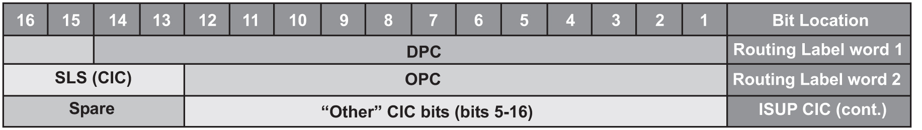
The EAGLE uses the least significant bit of the SLS to load share between linksets of a combined linkset. ITU ISUP messages use a SLS that is obtained from the lower 4 bits of the CIC field representing the circuit being used. Figure 3-2 shows the ITU ISUP routing label with the CIC field.

Figure 3-2 ITU ISUP Routing Label with CIC


img/c_add_ss7_linkset_ss7_config_dbadmin_ss7-fig1.jpg

CIC selection can be determined based on an odd or even method where a SSP uses either all odd CICs, or all even CICs, to help prevent “glaring” (that is, 2 SSPs attempting to seize the same trunk at the same time). This causes the least significant bit of the SLS to be fixed. If the least significant bit is fixed, inadequate load sharing occurs for the SS7 network. This situation can also occur within a single linkset (international), since the EAGLE also uses the lower 4 bits of the SLS (containing a fixed least significant bit) to select a link within a linkset.

This enhancement provides the user three options for addressing the problem:

  • Bit Rotation – The EAGLE rotates the 4 bits of the SLS, thus changing the least significant bit of the SLS. If selected, this option is applied to all ITU messages. This option is set with the slsrsb parameter of either the ent-ls or chg-ls commands. This action takes place on the outgoing linkset. More information on this option can be found in Bit Rotation.
  • Use of Other CIC Bit – The EAGLEderives the SLS from the bits 2 through 4 of the CIC to serve as the three lower bits of SLS, and one other bit of the CIC to serve as the most significant bit of the SLS. If selected, this option is only applied to ITU ISUP messages. This option is set with the slsocbit parameter of either the ent-ls or chg-ls commands. More information on this option can be found in Use of the Other CIC Bit.

    Before the Use of the Other CIC Bit option can be set, the Other CIC Bit Used feature must be turned on with the chg-feat command and the slsocb=on parameter. This can be verified with the SLSOCB = on entry of the rtrv-feat command output.

    The slsrsb and slsocbit parameters can only be specified for linksets that contain either an ITU international or ITU national adjacent point code (either a 14-bit or 24-bit ITU-N adjacent point code).

    The value of the slsrsb and slsocbit parameters are only displayed in the rtrv-ls command output when a specific linkset is being displayed with the rtrv-ls:lsn=<linkset name> command.

    Note:

    When two linksets are used as a combined linkset, both linksets should use the same slsrsb and slsocbit values.

    Note:

    If the randsls parameter of the chg-stpopts command, a system-wide option, is set to either all or class0, the EAGLE uses the Random SLS Generation feature to perform load sharing between ITU linksets. The slsrsb parameter value is ignored. However, the ent-ls and chg-ls commands allow the slsrsb parameter value to be specified. For more information on the Random SLS Generation feature, refer to Configuring the System for Random SLS Generation.
  • Incoming Bit Rotation - The EAGLE changes the least significant bit of the SLS on ANSI and ITU messages on incoming linksets by rotating the 4 bits of the SLS. This option is set with the islsrsb parameter of either the ent-ls or chg-ls commands. More information on this option can be found in Incoming Bit Rotation.

Only the link selection algorithm is modified by this feature, not the actual SLS field of the message (that is, the SLS value received by the EAGLE is the SLS value sent by the EAGLE).

Bit Rotation

To alleviate the situation of the EAGLE selecting the same linkset of a combined linkset, the customer can apply the bit rotation option. Bit rotation can be used, on a per linkset basis, to ensure the EAGLE does not use the static least significant bit (always 0 or always 1) in the received SLS for linkset selection.

When defining a link set using the ent-ls or chg-ls commands, the customer will be able to select which bit (1-4) of the SLS field to use as the least significant bit for link set selection. This rotation only affects the 4 bits of the SLS during linkset selection, as follows:

  • If bit 4 is selected, bit locations 4 3 2 1 will be rotated to 3 2 1 4.

    For example: SLS = 0110 becomes Rotated SLS = 1100. SLS = 1011 becomes Rotated SLS = 0111

  • If bit 3 is selected, bit locations 4 3 2 1 will be rotated to 2 1 4 3.

    For example: SLS = 0110 becomes Rotated SLS = 1001. SLS = 1011 becomes Rotated SLS = 1110

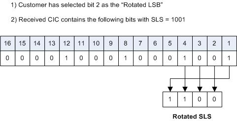
  • If bit 2 selected, bit locations 4 3 2 1 will be rotated to 1 4 3 2.

    For example: SLS = 0110 becomes Rotated SLS = 0011. SLS = 1011 becomes Rotated SLS = 1101

  • If bit 1 is selected, no rotation is performed, since bit 1 is the existing least significant bit. Bit 1 is the default value.

Figure 3-3 shows an example of bit rotation.

Figure 3-3 Example of Bit Rotation


img/bit_rotation_134355.jpg

After the SLS is rotated, the existing algorithm for selecting a linkset and signaling link is performed, and the message is sent out the selected link. Note that the SLS is modified only for the link selection algorithm, and is not modified in the outgoing message.

Use of bit rotation alone does not guarantee an even distribution of ITU-ISUP messages across all links within a linkset. The EAGLE uses all 4 bits of the SLS to determine the actual link to route messages. Since the static bit is simply rotated within the SLS, all possible values of the SLS field will still not be realized. A second option, Use of the Other CIC Bit, must be applied to guarantee even distribution across all links within the linkset.

Use of the Other CIC Bit

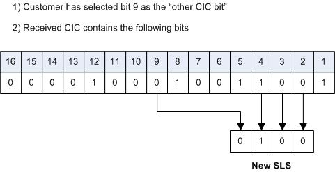
The Use of the Other CIC Bit option can be applied by the customer to alleviate the problem of the EAGLE not load sharing between all links within a linkset. When defining a linkset with the chg-ls or ent-ls command, the user can specify whether the Use of the Other CIC Bit option is to be used during link selection. If the option is to be used, the customer can also specify which bit (bits 5 through 16 of CIC) is to be used as the “other CIC bit”.

During link selection, the specified bit acts as the most significant bit of the new SLS, and bits 2 through 4 of the received CIC become the least significant bits of the new SLS.

Figure 3-4 shows how the new SLS field is generated using the “other CIC bit.”

Figure 3-4 SLS creation Using “Other CIC Bit”


img/use_other_cic_bit_134355.jpg

After the SLS is generated using the “other CIC bit”, the existing algorithm for selecting a linkset and signaling link is performed, and the message is sent out from the selected link. Note that the SLS is modified only for the link selection algorithm, and is not modified in the outgoing message.

Incoming Bit Rotation

Incoming Bit Rotation is set on the incoming linkset, where the existing SLS bit rotation option is set on the outgoing linkset. The algorithm used for rotating the SLS bits on outgoing linksets is also used on incoming linksets. This method provides additional capability to fairly distribute traffic across links and linksets, however it still does not guarantee an even distribution of messages for all set of input SLS values. Rotating SLS Bits on outgoing linksets is supported only for ITU linksets. Rotating SLS bits on incoming linksets is supported for ANSI and ITU linksets. For ITU linksets, the SLS value is only four bits and all four bits are considered for bit rotation. Table 3-4 shows examples of bit rotation for ITU linksets.

Table 3-4 ITU SLS Bit Rotation

Incoming ITU SLS Value Least Significant Bit Being Rotated Rotated SLS Value
0110 2 0011
1110 3 1011
0010 1 0010
1101 4 1011

For ANSI linksets, which may have a five or eight bit SLS value, the full five or eight bits are considered for link and linkset selection. Table 3-5 shows the rules that apply to rotating the SLS bit value in an ANSI linkset.

Table 3-5 ANSI Linkset Incoming Bit Rotation Rules

Rule Incoming Linkset ASL8 Value Incoming Linkset RSLS8 Value ISLSRSB Values SLSCNV/ Outgoing Linkset SLSCI Value Incoming SLS Bit Rotation (ISLSBR)
1 No No 1 - 5 No The least significant 5 bits of the SLS are considered for rotation.
2 No No 1 - 5 Yes The least significant 5 bits of the SLS are considered for rotation.
3 No Yes 1 - 8 No No incoming SLS bit rotation is performed. The 5-Bit to 8-Bit SLS Conversion feature must be turned on to perform incoming SLS bit rotation.
4 No Yes 1 - 8 Yes The 8 bit SLS value is obtained after the 5-bit to 8-bit SLS conversion is performed is considered for rotation.
5 Yes No 1 - 5 N/A The least significant 5 bits of the SLS are considered for rotation.
6 Yes Yes 1 - 8 N/A The 8-bit SLS value is considered for rotation.

Rotating the SLS bits on ANSI linksets is based on the combination of the ASL8, RSLS8, SLSCNV/SLSCI, and ISLSRSB parameter values.

The ASL8 parameter value for the incoming linkset specifies whether the adjacent node is sending messages with a 5-bit SLS or an 8-bit SLS.

If the ASL8 parameter value for the incoming linkset is No, and the global SLSCNV/SLSCI parameter value for the outgoing linkset is Yes, the 5-Bit to 8-Bit SLS Conversion feature is applied to the incoming 5-bit SLS value.

The RSLS8 parameter value for the incoming linkset specifies the number of SLS bits to be considered for rotation. If the RSLS8 value is Yes, 8 bits are considered for rotation. If the RSLS8 value is No, the least significant 5 bits of the SLS are considered for rotation. If the ASL8 value is No, the RSLS8 value is Yes, and the STPCNV/SLSCI value is No, then no rotation is performed. See Table 3-6.

Table 3-6 ANSI SLS Bit Rotation

Incoming ANSI SLS Incoming Linkset RSLS8 Value Least Significant Bit Being Rotated Outgoing ANSI SLS Rotated SLS Rule Applied
11000110 No Bit 2 11000110 11000011 5
01011110 Yes Bit 7 01011110 01111001 6
10010 No Bit 4 10110010 10101010 2
10010 Yes Bit 8 10110010 01100101 4
01101 No Bit 4 01101 10101 1
01101 Yes Bit 7 01101 No Rotation 3
The digits shown in bold show the digits that were added to the SLS value by the 5-Bit to 8-Bit SLS Conversion feature. The SLS bits are rotated in this manner.
  1. All the bits to the right side of the bit chosen to the least significant bit are removed as a block.
  2. The remaining bits are right justified.
  3. The block of digits that was removed in step 1 is inserted to the left of the bits that were right justified in step 2.

The new SLS value created after the SLS bits have been rotated is used for linkset and signaling link selection.

Combining the Bit Rotation, Use of the Other CIC Bit, Incoming Bit Rotation, and Random SLS Options

The Bit Rotation, Use of the Other CIC Bit, Incoming Bit Rotation, or Random SLS option, can be applied to provide and even distribution of ITU and ANSI messages sent by the EAGLE. If these options have been activated for a given linkset, the SLS field is processed in the following order.
  1. If the RANDSLS value (system-wide or on the incoming linkset) is on, then an 8-bit random SLS value is generated.
  2. If the Random SLS option is applied and the system-wide SLSREPLACE value is on, the randomly generated SLS value is replaced. Go to step 5.
  3. If the global SLSCNV/SLSCI value for the outgoing linkset is on, the 5-bit ANSI SLS value is converted to an 8-bit SLS value using the 5-Bit to 8-bit SLS Conversion feature.
  4. If the Random SLS option is not applied, the converted SLS value is modified using the Incoming Bit Rotation option.
  5. The modified SLS value is used by the existing linkset and signaling link selection algorithm to select a linkset and a signaling link.
  6. If the linkset type of the outgoing linkset is C (lst=c), the SLS value is modified using the standard fifth bit rotation, replaced in the MSU, and sent to the selected signaling link.

ITU TFR Procedures

Receiving TFR Messages

If ITU TFR procedures have been enabled for the linkset and a TFR message is received on that linkset, the EAGLE marks the route to the destination as restricted and performs controlled rerouting of the messages that are destined for the destination specified in the TFR message.

If ITU TFR procedures have not been enabled for the linkset and a TFR message is received on that linkset, the TFR message is converted to a TFA (transfer allowed) message and traffic is routed to the destination specified in the TFR message. When this condition is present and a TFR is received on this linkset, UIM 1233 is displayed showing that a TFR was received on a linkset that does not support the TFR procedure.

When a TFR message is received for a route that is already prohibited, and no alternative route exists, the traffic to the concerned node is restarted toward the signaling point from which the TFR message was received.

Invalid TFR messages

The TFR message is ignored under any of these conditions:

  • The TFR message is not from an adjacent point code.
  • The point code specified in the TFR message is being sent from that same point code.
  • The TFR message is from an unknown destination.
  • The TFR message is from an adjacent point code, but the adjacent point code is not the route for concerned point code.
  • If the route to the concerned point code is already restricted.
  • The route to concerned point code not found or is unavailable.

Sending TFR Messages

The EAGLE must send a TFR message containing the affected point code (restricted destination) to all accessible adjacent nodes, whose linkset has the TFR procedure enabled, when the following conditions are in effect:

  • When long term failure occurs on the ITU-N linkset (primary) used to route messages to the affected point code. Long term failure occurs when all links of a linkset remain unavailable for more than the amount of time specified by level 3 timer T11.
  • While waiting for “long term failure” to be determined, if congestion (or “danger of congestion”) is detected on an alternate linkset used to route messages to the affected point code, then TFRs are sent immediately without waiting for level 3 timer T11 to expire. For example: level 3 timer T11 is set to 30 seconds, the links of the linkset to the adjacent node fail and MSUs are now sent out the alternate linkset. Within 10 seconds of the failure, congestion is detected on the alternate linkset, so TFR messages are sent to each adjacent point code (if linkset has ITUTFR procedures enabled) for each destination (affected point code) routed through that node.
  • When an adjacent node becomes accessible by an alternate route, the EAGLE sends a TFR for each destination that is restricted to the node.
  • During restarts, TFRs are broadcast to all accessible adjacent nodes for each restricted destination.

Unlike the ANSI network, the ITU national network does not use response method TFR messages. The ITU national network only uses broadcast method TFR messages that are sent to all adjacent nodes under the conditions described above.

Note:

In ANSI networks, response method TFRs are sent to adjacent nodes in response to a MSU, when that node continues to send MSUs after a broadcast method TFR has already been sent.

The EAGLE maintains the status (allowed, restricted, or prohibited) for all destinations. XREF shows the type of message sent when a destination transitions from one status to another.

Table 3-7 Route Management Messages Sent on Status Transition

Status Transition ITUTFR Procedures Enabled ITUTFR Procedures Disabled

Prohibited to Restricted

TFR

TFA

Allowed to Restricted

TFR

None

Restricted to Prohibited

TFP

TFP

Restricted to Allowed

TFA

None

Per-Linkset Random SLS

To achieve load balancing of outgoing traffic on ITU linksets, linksets that have either an ITU-I, 14-bit ITU-N, or 24-bit ITU-N adjacent point code assigned, the EAGLE 5 ISS currently uses the Random SLS option to generate a new SLS (signaling link selector) value. The randomly generated SLS value is used to select an outgoing signaling link and linkset. Random SLS generation applies to either Class 0 SCCP messages or to both Class 0 and Class 1 SCCP messages. The Random SLS option is configured using the randsls parameter of the chg-stpopts command. Refer to Configuring the System for Random SLS Generation for more information on configuring the Random SLS option.

This method of selecting outgoing signaling links and linksets is applied system-wide to all ITU linksets. This may cause problems for some end nodes that may have specific requirements for handling incoming SCCP messages, such as sequencing of Class 1 SCCP messages.

The Per-Linkset Random SLS feature provides the ability to apply Random SLS generation to Class 0 and Class 1SCCP messages on specific outgoing ITU linksets and to Class 0 SCCP messages and ISUP messages on specific incoming ANSI linksets. The randsls parameter of either the ent-ls or chg-ls command applies this feature to the linkset. The randsls parameter has three values:

  • off – Random SLS generation is not applied to the specified linkset.
  • class0 – Random SLS generation is applied to only Class 0 SCCP messages.
  • all – Random SLS generation is applied to both Class 0 and Class 1 SCCP messages on a specific outgoing ITU linksets, and to both Class 0 SCCP and ISUP messages on specific ANSI linksets.

When per-linkset random SLS is applied to ANSI linksets, linksets that have ANSI adjacent point codes, the SLS of the message is replaced with a randomly generated SLS, only if the slsreplace parameter value is set to yes. The slsreplace parameter value is shown in the rtrv-ss7opts output. If the slsreplace parameter value is no, the EAGLE 5 ISS uses the randomly generated SLS to select the signaling link, but the message retains the original SLS. If the linkset’s asl8 or slsci parameter value is off, or the chg-stpopts slscnv parameter is off, a 5-bit SLS is placed in the message. The three most significant bits of the SLS are zeroes. If the linkset’s asl8 or slsci parameter value is on, or the slscnv parameter of the chg-stpopts command is on, an 8-bit SLS is placed in the message. The linkset’s asl8 parameter value is not used for internal linkset and signaling link selection. The linkset's asl8 parameter applies only to incoming linksets. The linkset's slsci parameter applies only to outgoing linksets. The randomly generated SLS value is used for internal linkset and signaling link selection. When an ANSI to ITU conversion takes place, the randomly generated SLS value for the incoming ANSI linkset is used for internal linkset and signaling link selection and Random SLS generation on outgoing linkset is not performed.

The randsls parameter is optional. If the randsls parameter is not specified when adding a linkset with the ent-ls command, the value of the randsls parameter is off. If the randsls parameter is not specified when changing a linkset with the chg-ls command, the value of the randsls parameter is not changed.

The value of the randsls parameter assigned to the linkset is displayed in the RANDSLS column of the rtrv-ls command output. The RANDSLS column is displayed only when a specific linkset is being displayed with the rtrv-ls:lsn=<linkset name> command. All linksets having a particular randsls value can be displayed by entering the rtrv-ls command with the randsls parameter with one of these values:

  • off – Displays the linksets where random SLS generation is disabled.
  • class0 – Displays the linksets where random SLS generation for Class 0 SCCP traffic is enabled.
  • all – Displays the linksets where random SLS generation for Class 0 and Class 1 SCCP traffic on a specific outgoing ITU linksetsis enabled, and Class0 SCCP and ISUP messages on specific incoming ANSI linksets is enabled..

For random SLS generation to be performed on a specific linkset, the randsls parameter value for that linkset must be set to either class0 or all. The system-wide random SLS STP option randsls must be set to perls using the chg-stpopts command with the randsls=perls parameter. Refer to Configuring the System for Random SLS Generation for more information on configuring the system-wide Random SLS option, and, if Random SLS is applied to ANSI linksets, to configure the SS7 option for replacing the SLS in the message with the randomly generated SLS.

It is recommended that when configuring randsls values on two linksets that are in a combined linkset that the randsls values for these linksets are the same. If these values are not the same, undesired SLS distribution of the traffic on these linksets may result.

Verifying the Gateway Screening Configuration for a Linkset

This procedure is used to verify that the screen set that will be assigned to the linkset, and its associated screens, is in the database.

  1. Display the current linkset configuration using the rtrv-ls command.

    This is an example of the possible output.

    
    rlghncxa03w 08-12-10 11:43:04 GMT EAGLE5 40.0.0
    
                                     L3T SLT              GWS GWS GWS
    LSN           APCA   (SS7)  SCRN SET SET BEI LST LNKS ACT MES DIS SLSCI NIS
    e1e2          001-207-000   none 1   1   no  B   6    off off off no    off
    ls04          001-002-003   scr2 1   1   no  a   4    off off off yes   off
    ls1305        001-005-000   none 1   1   no  A   1    off off off no    off
    ls1307        001-007-000   none 1   1   no  A   1    off off off no    off
    e1m1s1        001-001-003   none 1   1   no  A   7    off off off no    off
    e1m1s2        001-001-002   none 1   1   no  A   7    off off off no    off
    
                                     L3T SLT              GWS GWS GWS
    LSN           APCI   (SS7)  SCRN SET SET BEI LST LNKS ACT MES DIS SLSCI NIS
    e1e2i         1-207-0       none 1   1   no  B   4    off off off ---   on
    ls1315        0-015-0       none 1   1   no  A   1    off off off ---   off
    ls1317        0-017-0       none 1   1   no  A   1    off off off ---   on
    e1m2s1        1-011-1       none 1   1   no  A   7    off off off ---   off
    e1m2s2        1-011-2       none 1   1   no  A   7    off off off ---   off
    
    Link set table is (10 of 1024) 1% full.
    
    A screenset that is assigned to another linkset can be assigned to the new linkset or the linkset that is being changed. If you wish to use a screenset shown in the rtrv-ls output, continue the procedure by performing one of these actions.
    • If you wish to examine the content of the screen set, continue the procedure with the 3.
    • If you do not wish to examine the content of the screen set, and the screen set is being assigned to a new linkset, this procedure is finished. If the screen set is being assigned to an existing linkset, continue the procedure with 5.

    If you do not wish to use a screenset shown in the rtrv-ls output, continue the procedure with the 2.

  2. Verify that the gateway screening screen set that is to be assigned to the linkset is in the database by entering the rtrv-scrset command.

    This is an example of the possible output.

    
    rlghncxa03w 08-12-28 16:37:05 GMT EAGLE5 40.0.0
    ENTIRE GWS DATABASE IS 1% FULL
    CDPA + AFTPC TABLES ARE 1% FULL
    SCREEN SET TABLE IS (12 OF 255) 5% FULL
    THERE ARE 0 SEAS SCREEN SETS USED ( prefix 00nn )
    THERE ARE 12 EAGLE SCREEN SETS USED
    
    SCRN  NSFI    NSR/ACT  FULL  RULES  TABLES  DESTFLD
    fld1  OPC     fld2       1%     5   4       NO
    gws1  OPC     gws4       1%     9   7       NO
    gws2  BLKOPC  gws5       1%     5   4       NO
    ls01  SIO     ls02       1%     3   3       YES
    scr1  OPC     opc1       1%    13   10      YES
    scr2  OPC     opc2       2%    75   22      YES
    scr3  OPC     opc3       2%    75   22      YES
    scr4  OPC     opc1      51%  2075   22      NO
    scr5  OPC     opc1      51%  2075   22      YES
    scr6  OPC     opc1      51%  2075   22      NO
    ss28  OPC     opc1      51%  2075   22      YES
    wrd1  SIO     iec        1%     6   5       YES
    

    If you wish to examine the contents of a particular screen set, continue the procedure with 3.

    If you do not wish to examine the content of the screen set, and the screen set is being assigned to a new linkset, this procedure is finished. If the screen set is being assigned to an existing linkset, continue the procedure with 5.

    If the screen set is being assigned to a new linkset, this procedure is finished. If the screen set is being assigned to an existing linkset, continue the procedure with 5.

  3. Enter the rtrv-scrset command specifying a screen set name shown in the SCRN field of either the rtrv-scrset command executed in 2 or the rtrv-ls command executed in 1.

    For this example, enter this command.

    rtrv-scrset:scrn=scr1

    This is an example of the possible output.

    
    rlghncxa03w 08-12-14 16:39:04 GMT EAGLE5 40.0.0
    SCRN  NSFI    NSR/ACT   RULES  DESTFLD
    scr1  OPC     opc1         1   Y
          BLKDPC  bkd2         2
          CGPA    cgp1         3
          TT      tt1          1
          TT      tt2          1
          TT      tt3          1
          CDPA    cdp1         1
          CDPA    cdp2         1
          CDPA    cdp3         1
          AFTPC   end1         1
    

    The output of this command shows the screens that make up the screen set. These screens can be examined by entering the gateway screening retrieve command corresponding to the value in the NSFI field and specifying the screening reference name shown in the NSR/ACT field.

    If you wish to examine the content of these screens, continue the procedure with 4.

    If you do not wish to examine the content of these screens, and the screen set is being assigned to a new linkset, this procedure is finished. If the screen set is being assigned to an existing linkset, continue the procedure with 5.

  4. Enter the gateway screening retrieve command corresponding to the value in the NSFI field and specifying the screening reference name shown in the NSR/ACT field

    For this example, enter these commands.

    rtrv-scr-opc:sr=opc1

    The following is an example of the possible output.

    
    rlghncxa03w 08-12-25 15:30:30 GMT  EAGLE5 40.0.0
    SCREEN = ALLOWED OPC
    SR    NI       NC       NCM      NSFI    NSR/ACT
    opc1  001      001      001      BLKOPC  bkd2
    

    rtrv-scr-blkdpc:sr=bkd2

    The following is an example of the possible output.

    
    rlghncxa03w 08-12-25 15:30:30 GMT  EAGLE5 40.0.0
    SCREEN = BLOCKED OPC
    SR    NI       NC       NCM      NSFI    NSR/ACT
    bkd2  002      002      002      FAIL    ------
    bkd2  C        C        C        CGPA    cgp1
    

    rtrv-scr-cgpa:sr=cgp1

    The following is an example of the possible output.

    
    rlghncxa03w 08-12-25 15:30:30 GMT  EAGLE5 40.0.0
    SCREEN = ALLOWED CGPA
    SR    NI       NC       NCM      SSN      RI   SCCPMT   NSFI    NSR/ACT
    cgp1  007      007      007      250      SSN  017      TT      tt1
    cgp1  007      007      008       50      SSN  017      TT      tt2
    cgp1  007      007      009       75      SSN  017      TT      tt3
    

    rtrv-scr-tt:sr=tt1

    The following is an example of the possible output.

    
    rlghncxa03w 08-12-25 15:30:30 GMT  EAGLE5 40.0.0
    SCREEN = ALLOWED TT
    SR    TYPE     NSFI   NSR/ACT
    tt1   250      CDPA   cdp1
    

    rtrv-scr-tt:sr=tt2

    The following is an example of the possible output.

    
    rlghncxa03w 08-12-25 15:30:30 GMT  EAGLE5 40.0.0
    SCREEN = ALLOWED TT
    SR    TYPE     NSFI   NSR/ACT
    tt2     50     CDPA   cdp2
    

    rtrv-scr-tt:sr=tt3

    The following is an example of the possible output.

    
    rlghncxa03w 08-12-25 15:30:30 GMT  EAGLE5 40.0.0
    SCREEN = ALLOWED TT
    SR    TYPE     NSFI   NSR/ACT
    tt3   100      CDPA   cdp3
    

    rtrv-scr-cdpa:sr=cdp1

    The following is an example of the possible output.

    
    rlghncxa03w 08-12-25 15:30:30 GMT  EAGLE5 40.0.0
    SCREEN = ALLOWED CDPA
    SR    NI       NC      NCM       SSN      SCMGFID  NSFI    NSR/ACT
    cdp1  007      007     007       001      100      AFTPC   end1
    

    rtrv-scr-cdpa:sr=cdp2

    The following is an example of the possible output.

    
    rlghncxa03w 08-12-25 15:30:30 GMT  EAGLE5 40.0.0
    SCREEN = ALLOWED CDPA
    SR    NI       NC      NCM       SSN      SCMGFID  NSFI    NSR/ACT
    cdp2  007      007     008       001      120      AFTPC   end1
    

    rtrv-scr-cdpa:sr=cdp3

    The following is an example of the possible output.

    
    rlghncxa03w 08-12-25 15:30:30 GMT  EAGLE5 40.0.0
    SCREEN = ALLOWED CDPA
    SR    NI       NC      NCM       SSN      SCMGFID  NSFI    NSR/ACT
    cdp3  007      007     009       001      150      AFTPC   end1
    

    rtrv-scr-aftpc:sr=end1

    The following is an example of the possible output.

    
    rlghncxa03w 08-12-25 15:30:30 GMT  EAGLE5 40.0.0
    SCREEN = ALLOWED AFTPC
    SR    NI       NC       NCM      SSN      NSFI    NSR/ACT
    end1  008      008      008      250      STOP    ------
    

    If you do not with to assign this screen set to the linkset, perform the "Adding a Screen Set" procedure in the Database Administration Manual - Gateway Screening to add the desired screen set to the database.

    If the screen set is being assigned to a new linkset, this procedure is finished. If the screen set is being assigned to an existing linkset, continue the procedure with 5.

  5. Remove the existing screen set assignment from the linkset by entering the chg-ls command with the name of the linkset and the scrn=none parameter.

    For this example, enter this command.

    chg-ls:lsn=ls04:scrn=none

    When this command has successfully completed, this message should appear.

    
    rlghncxa03w 08-12-17 16:23:21 GMT  EAGLE5 40.0.0
    Link set table is ( 19 of 1024)  2% full
    CHG-LS: MASP A - COMPLTD
    
  6. Verify the changes using the rtrv-ls command specifying the linkset name specified in 5 with the lsn parameter.

    For this example, enter this command.

    rtrv-ls:lsn=ls04

    This is an example of the possible output.

    
    rlghncxa03w 09-10-17 11:43:04 GMT EAGLE5 41.1.0
    
                                     L3T SLT              GWS GWS GWS
    LSN           APCA   (SS7)  SCRN SET SET BEI LST LNKS ACT MES DIS SLSCI NIS
    ls04          001-002-003   none 1   1   no  a   4    off off off yes   off
    
              CLLI         TFATCABMLQ MTPRSE ASL8
              ls04clli     2          no     no
    
              IPGWAPC MATELSN    IPTPS LSUSEALM SLKUSEALM GTTMODE
              no      ---------- ---   ---      ---       CdPA
    
                                      L2T               PCR  PCR 
              LOC   LINK SLC TYPE     SET  BPS    ECM   N1   N2
              1205  b    0   LIMDS0   1    56000  BASIC ---  -----
              1213  b    1   LIMDS0   1    56000  BASIC ---  -----
              1211  a    2   LIMDS0   1    56000  BASIC ---  -----
              1207  b    3   LIMDS0   1    56000  BASIC ---  -----
    
    Link set table is ( 19 of 1024)  2% full
    
  7. Back up the new changes using the chg-db:action=backup:dest=fixed command.

    These messages should appear, the active Maintenance and Administration Subsystem Processor (MASP) appears first.

    
    BACKUP (FIXED) : MASP A - Backup starts on active MASP.
    BACKUP (FIXED) : MASP A - Backup on active MASP to fixed disk complete.
    BACKUP (FIXED) : MASP A - Backup starts on standby MASP.
    BACKUP (FIXED) : MASP A - Backup on standby MASP to fixed disk complete.
    

    This procedure is finished.

Figure 3-5 Verifying the Gateway Screening Configuration for a Linkset


Sheet 1 of 2


Sheet 2 of 2

Configuring the MTP Restart Feature

This procedure is used to configure the MTP Restart feature with the following commands and parameters.
  • chg-feat - mtprs=on (to turn on MTP Restart for ANSI signaling links) and itumtprs=on (to turn on MTP Restart for ITU signaling links)
  • chg-stpopts
    • on=mtprsi - to enable the MTP Restart process, or off=mtprsi , to disable the MTP Restart process. When the on=mtprsi parameter is specified for the chg-stpopts command, the value yes is shown in the MTPRSI field of the rtrv-stpopts output. When the off=mtprsi parameter is specified for the chg-stpopts command, the value no is shown in the MTPRSI field of the rtrv-stpopts output. The system default value for this option is no.
    • mtprsit - the MTP restart isolation timer - 2000 to 900000 milliseconds. The system default value is 5000 milliseconds.

The MTP restart feature is applied to the signaling links in a linkset by specifying the mtprse=yes parameter of the ent-ls or chg-ls commands. Perform Adding an SS7 Linkset or Changing an SS7 Linkset to specify the mtprse value for a linkset.

If the MTP restart feature is turned on, the alignment of all signaling links is delayed until all the LIMs containing signaling links are in service. This allows the EAGLE to be restored to network service in an orderly fashion and allows all the LIMs containing signaling links to participate in the MTP restart process. The amount of time that the alignment of the signaling links is delayed is dependent on the number of LIMs and DCMs in the EAGLE and is shown in Table 3-8. Table 3-8 shows and example of MTP signaling link alignment delay for LIMs.

Note:

The MTP restart feature can be used on linksets containing non-IP signaling links, IP signaling links with the ipliml2=m2pa parameter, or IPSG signaling links with the ipsg=yes and adapter=m2pa parameters.

Table 3-8 MTP Restart Signaling Link Alignment Delay

Number of LIMs Containing Signaling Links Signaling Link Alignment Delay

1 to 64

62 seconds

64 to 127

97 seconds

128 to 191

132 seconds

192 or more

167 seconds

If the ANSI MTP restart feature is on (MTPRS = on in the rtrv-feat command output), the mtprsi parameter is set to yes, and at least one ANSI linkset has the mtprse parameter set to yes, the EAGLE starts these level 3 timers; T22, T23, T24, T25, T26, T28, T29, and T30 to control the behavior of the MTP restart feature. These timers control when the TRA and TRW network management messages are sent to the nodes adjacent to the EAGLE when the EAGLE is going through the MTP restart process. When these timers are first introduced to the EAGLE, the system default values for these timers are:

  • T22 - 10 seconds
  • T23 - 10 seconds
  • T24 - 10 seconds
  • T25 - 30 seconds
  • T26 - 12 seconds
  • T28 - 3 seconds
  • T29 - 60 seconds
  • T30 - 30 seconds.

To change the values of these timers, perform Changing Level 3 Timers.

If the ITU MTP restart feature is on (ITUMTPRS = on in the rtrv-feat command output), the mtprsi parameter is set to yes, and at least one ITU linkset has the mtprse parameter set to yes, the EAGLE starts these level 3 timers; IT18, IT19, IT20, and IT21 to control the behavior of the ITU MTP restart feature. These timers control when the TRA and TRW network management messages are sent to the nodes adjacent to the EAGLE when the EAGLE is going through the MTP restart process. When these timers are first introduced to the EAGLE, the default values for these timers are:

  • IT18 - 50 seconds
  • IT19 - 67 seconds
  • IT20 - 59 seconds
  • IT21 - 63 seconds.

To change the values of these timers, perform Changing Level 3 Timers.

If both the ANSI and ITU MTP restart features are on, the mtprsi parameter is set to yes, and at least one ANSI and ITU linkset has the mtprse parameter set to yes, the EAGLE starts the level 3 timers for both the ANSI and ITU MTP restart features to control the behavior of both the ANSI and ITU MTP restart features.

  1. If you wish to use either the ANSI MTP restart feature or the ITU MTP restart feature, enter the rtrv-feat command to verify that either of these features are on.

    The entry MTPRS = on in the rtrv-feat command output shows that the ANSI MTP restart feature is on. The entry ITUMTPRS = on in the rtrv-feat command output shows that the ITU MTP restart feature is on. In this example, both features are off.

    Note:

    The rtrv-feat command output contains other fields that are not used by this procedure. If you wish to see all the fields displayed by the rtrv-feat command, see the rtrv-feat command description in Commands User's Guide.

    If both the ANSI and ITU MTP restart feature are on, continue the procedure with 4.

    If you are not going to turn the ANSI MTP restart feature on, or if the output of the rtrv-feat command in this step shows that the ANSI MTP restart feature is on (shown by the MPTRS = on entry), continue the procedure with 3.

  2. Turn the ANSI MTP restart feature on by entering this command.

    chg-feat:mtprs=on

    Note:

    Once the ANSI MTP restart feature is turned on with the chg-feat command, it cannot be turned off.

    The ANSI MTP restart feature must be purchased before you turn the feature on with the chg-feat command. If you are not sure if you have purchased the ANSI MTP restart feature, contact your Sales Representative or Account Representative.

    When this command has successfully completed, this message should appear.

    
    rlghncxa03w 06-10-10 11:43:04 GMT EAGLE5 36.0.0
    CHG-FEAT: MASP A - COMPLTD
    

    Note:

    If you are not going to turn the ITUMTP restart feature on, or if the output of the rtrv-feat command in 1 shows that the ITU MTP restart feature is on (shown by the ITUMPTRS = on entry), continue the procedure with 4.
  3. Turn the ITU MTP restart feature on by entering this command.

    chg-feat:itumtprs=on

    Note:

    Once the ITU MTP restart feature is turned on with the chg-feat command, it cannot be turned off.

    The ITU MTP restart feature must be purchased before you turn the feature on with the chg-feat command. If you are not sure if you have purchased the ITU MTP restart feature, contact your Sales Representative or Account Representative.

    When this command has successfully completed, this message should appear.
    
    rlghncxa03w 06-10-10 11:43:04 GMT EAGLE5 36.0.0
    CHG-FEAT: MASP A - COMPLTD
    
  4. Enter the rtrv-stpopts command to display the value of the MTPRSI and MTPRSIT fields. This is an example of the possible output.
    
    rlghncxa03w 06-10-17 16:02:05 GMT  EAGLE5 36.0.0
    STP OPTIONS
    -----------------------
    MTPRSI              no
    MTPRSIT           5000
    

    Note:

    The rtrv-stpopts command output contains other fields that are not used by this procedure. If you wish to see all the fields displayed by the rtrv-stpopts command, see the rtrv-stpopts command description in Commands User's Guide.

    To change the value of the MTPRSI or the MTPRSIT fields, continue the procedure with 5.

    If you do not wish to change the value of the MTPRSI or the MTPRSIT fields, continue the procedure with 7.

  5. Change the MTPRSI or MTPRSIT values by entering the chg-stpopts command with one or more of these parameters.
    • :on=mtprsi - to enable the MTP restart process.
    • :off=mtprsi - to disable the MTP restart process.
    • :mtprsit - to specify a new value for the MTP restart isolation timer.

    For this example, enter this command.

    chg-stpopts:on=mtprsi:mtprsit=7500

    For this example, the MTP restart process is enabled and the value of the MTP restart isolation timer is changed.

    When the chg-stpopts command has successfully completed, this message should appear.

    
    rlghncxa03w 06-10-07 00:22:57 GMT  EAGLE5 36.0.0
    CHG-STPOPTS: MASP A - COMPLTD
    
  6. Verify the changes using the rtrv-stpopts command.

    This is an example of the possible output.

    
    rlghncxa03w 06-10-17 16:02:05 GMT  EAGLE5 36.0.0
    STP OPTIONS
    -----------------------
    MTPRSI             yes
    MTPRSIT           7500
    

    Note:

    The rtrv-stpopts command output contains other fields that are not used by this procedure. If you wish to see all the fields displayed by the rtrv-stpopts command, see the rtrv-stpopts command description in Commands User's Guide.
  7. Back up the new changes using the chg-db:action=backup:dest=fixed command.

    These messages should appear, the active Maintenance and Administration Subsystem Processor (MASP) appears first.

    
    BACKUP (FIXED) : MASP A - Backup starts on active MASP.
    BACKUP (FIXED) : MASP A - Backup on active MASP to fixed disk complete.
    BACKUP (FIXED) : MASP A - Backup starts on standby MASP.
    BACKUP (FIXED) : MASP A - Backup on standby MASP to fixed disk complete.
    

Figure 3-6 Configuring the MTP Restart Feature


Configuring the 5-Bit to 8-Bit SLS Conversion Feature

This procedure is used to configure the 5-Bit to 8-Bit SLS Conversion feature using the chg-stpopts command with the slscnv parameter.

The slscnv parameter of the chg-stpopts command has three values: on, off, and perls.

  • slscnv=on – 5-bit to 8-bit conversion is performed on all linksets in the EAGLE, regardless of what the value of the slsci parameter of the ent-ls or chg-ls command is for the specific linkset. If the asl8=yes parameter of either the ent-ls or chg-ls commands is assigned to the linkset, no SLS conversion is performed.
  • slscnv=off – 5-bit to 8-bit conversion is not performed on the linksets in the EAGLE, regardless of what the value of the slsci parameter of the ent-ls or chg-ls command is for the specific linkset.
  • slscnv=perls – 5-bit to 8-bit SLS conversion is only performed on the MSUs arriving at the EAGLE on linksets that have the asl8=no parameter assigned to them, and leaving the EAGLE on linksets that have the slsci=yes parameter assigned to them. The asl8 and slsci parameters are configured with either the ent-ls or chg-ls commands.

5-Bit to 8-Bit SLS conversion is performed based on the values assigned to the slsci and asl8 parameters for the linkset and the slscnv parameter of the chg-stpopts command.

Note:

The slsci and asl8 parameters can be specified only for linksets containing ANSI adjacent point codes.

The slsci parameter indicates whether the 5-bit to 8-bit SLS conversion feature is used to select signaling links for outgoing messages on the specified link set. If the slsci=yes parameter is specified, the EAGLE replaces any 5-bit SLS values contained in received messages with a random 8-bit value before they are used by the EAGLE to select the outgoing signaling link in that linkset. The 5-bit to 8-bit SLS conversion is also controlled by the slscnv parameter of the chg-stpopts command.

The asl8 parameter shows if the node adjacent to the EAGLE is sending MSUs with 8-bit SLSs. If the asl8=yes parameter is specified with the lst=a parameter (a linkset containing access signaling links), this indicates that the originator of the MSUs is generating 8-bit SLSs. For other linkset types, the asl8=yes parameter indicates that the adjacent node is converting 5-bit SLSs to 8-bit SLSs. The SLS in MSUs received by the EAGLE on a linkset that has the asl8=yes parameter assigned to it will not be converted. These MSUs are assumed to contain 8-bit SLSs. If the asl8=no parameter is specified for the linkset, the SLS will be converted to an 8-bit SLS. The value of the asl8 parameter is only displayed in the rtrv-ls command output when a specific linkset is being displayed with the rtrv-ls:lsn=<linkset name> command.

The interaction between the slsci and asl8 parameters of the ent-ls command and the slscnv parameter of the chg-stpopts command is shown in Table 3-9.

Table 3-9 Signaling Link Selector (SLS) Conversion (ANSI Linksets Only)

CHG-STPOPTSSLSCNV Parameter Value Outgoing Linkset SLSCI Parameter Value Incoming Linkset ASL8 Parameter Value Result

ON

Not Applicable

YES

The adjacent node is sending 8-bit SLSs. No SLS conversion is performed on MSUs received on this linkset.

ON

Not Applicable

NO

The adjacent node is not sending 8-bit SLSs. 5-bit to 8-bit SLS conversion on MSUs received on this linkset.

OFF

Not Applicable

YES

The adjacent node is sending 8-bit SLSs. No SLS conversion is performed on any linksets.

OFF

Not Applicable

NO

The adjacent node is not sending 8-bit SLSs. 5-bit to 8-bit SLS conversion is not performed on all linksets.

PERLS*

YES

YES

The adjacent node is sending 8-bit SLSs. No SLS conversion is performed.

PERLS*

YES

NO

The adjacent node is not sending 8-bit SLSs. 5-bit to 8-bit SLS conversion is performed.

PERLS*

NO

YES

The adjacent node is sending 8-bit SLSs. No SLS conversion is performed.

PERLS*

NO

NO

The adjacent node is not sending 8-bit SLSs. 5-bit to 8-bit SLS conversion is not performed.

*When the slscnv=perls parameter is specified with the chg-stpopts command, 5-bit to 8-bit SLS conversion is only performed on the MSUs arriving at the EAGLE on linksets that have the asl8=no parameter of the ent-ls command assigned to them, and leaving the EAGLE on linksets that have the slsci=yes parameter of the ent-ls command assigned to them.

When a 5-bit ANSI SLS is converted to an 8-bit ANSI SLS, the three most significant bits of the SLS are set using a function of originating point code and incoming signaling link. This ensures that MSUs with the same originating point code, SLS, and incoming signaling link will always have the same SLS after the conversion, guaranteeing that the MSUs arrive at the destination in the same sequence that they were sent.

5-bit to 8-bit SLS conversion is performed under these conditions.

  • The incoming linkset is an ANSI linkset, a linkset containing an ANSI adjacent point code.
  • The asl8=no parameter of the ent-ls or chg-ls command is assigned to the incoming linkset.
  • The outgoing linkset is an ANSI linkset.
  • The slscnv=on parameter of the chg-stpopts command is specified
  • The slscnv=perls parameter of the chg-stpopts command is specified and slsci=yes parameter of the ent-ls or chg-ls command assigned to the outgoing linkset.
  • The three most significant bits of the SLS in the MSU are zero.

All ANSI MSUs originating from the EAGLE have an 8-bit SLS.

The EAGLE also converts ANSI SLSs to ITU SLSs, and ITU SLSs to ANSI SLSs.

When an ITU SLS is converted to an ANSI SLS, the ITU SLS is always converted to an ANSI 5-bit SLS. If the MSU containing the converted SLS is rerouted because of a link outage, the SLS may be converted from a 5-bit SLS to an 8-bit SLS.

When an ANSI SLS is converted to an ITU SLS, the ANSI SLS is always converted to an ITU 4-bit SLS.

The EAGLE does not convert a 4-bit ITU SLS to an 8-bit ANSI SLS.

The 5-bit to 8-bit SLS conversion takes place during the routing process, after the linkset is selected, but before the signaling link is selected. The ITU to ANSI SLS conversion takes place during the ANSI to ITU MSU conversion and after the outgoing signaling link is chosen.

  1. Display the existing value for the slscnv parameter by entering the rtrv-stpopts command.

    The value for the slscnv parameter is shown in the SLSCNV field. This is an example of the possible output.

    
    rlghncxa03w 08-12-17 16:02:05 GMT  EAGLE5 40.0.0
    STP OPTIONS
    -----------------------
    SLSCNV              on
    

    Note:

    The rtrv-stpopts command output contains other fields that are not used by this procedure. If you wish to see all the fields displayed by the rtrv-stpopts command, see the rtrv-stpopts command description in Commands User's Guide.

    If the slscnv parameter is not being changed, no further action is necessary. The procedure is finished.

    If you wish to change the slscnv parameter value, continue the procedure with 2.

  2. Change the slscnv parameter value using the chg-stpopts command.

    For this example, the value of the slscnv parameter is being changed from on to perls. Enter this command.chg-stpopts:slscnv=perls. When this command has successfully completed, this message should appear.

    
    rlghncxa03w 08-12-07 00:22:57 GMT  EAGLE5 40.0.0
    CHG-STPOPTS: MASP A - COMPLTD
    
  3. Verify the changes using the rtrv-stpopts command.

    This is an example of the possible output.

    
    rlghncxa03w 08-12-17 16:02:05 GMT  EAGLE5 40.0.0
    STP OPTIONS
    -----------------------
    SLSCNV           perls
    

    Note:

    The rtrv-stpopts command output contains other fields that are not used by this procedure. If you wish to see all the fields displayed by the rtrv-stpopts command, see the rtrv-stpopts command description in Commands User's Guide.
  4. Back up the new changes using the chg-db:action=backup:dest=fixed command.

    These messages should appear, the active Maintenance and Administration Subsystem Processor (MASP) appears first.

    
    BACKUP (FIXED) : MASP A - Backup starts on active MASP.
    BACKUP (FIXED) : MASP A - Backup on active MASP to fixed disk complete.
    BACKUP (FIXED) : MASP A - Backup starts on standby MASP.
    BACKUP (FIXED) : MASP A - Backup on standby MASP to fixed disk complete.
    

Figure 3-7 Configuring the 5-Bit to 8-Bit SLS Conversion Feature


Sheet 1 of 2


Sheet 2 of 2

Using Proxy Point Codes and Secondary Point Codes when Adding a Linkset

This procedure is used to verify that the following items are configured in the database.
  • Proxy point codes for adding proxy linksets
  • Secondary point codes for adding multiple linksets with the same adjacent point code.

To add a proxy linkset, a proxy point code must be assigned to the APC of the linkset, a proxy point code must be assigned to the linkset with the ppc/ppca/ppci/ppcn/ppcn24 parameter, and the linkset type must be prx. A quantity of proxy point codes must be enabled with the enable-ctrl-feat command before a proxy point code and a proxy linkset can be added. The first time a proxy linkset is added, the proxy point code that is assigned to the linkset must be the same proxy point code that is assigned to the APC of the proxy linkset. A maximum of 10 linksets can be added using the same proxy point code. For more information on proxy point codes, refer to Proxy Point Codes.

To add more than one linkset with the same APC, the Multiple Linksets to Single Adjacent PC feature must be enabled and turned on. The database can contain a maximum of six linksets that have the same APC. If the linkset is not a proxy linkset (linkset types A, B, C, D, or E), a secondary point code (shown in the rtrv-spc output) must be specified with the linkset. The network type and format of the secondary point code must be the same as the APC of the linkset. Secondary point codes can also be assigned to the APC of the linkset when the point code is added in the database with the ent-dstn or chg-dstn commands. The secondary point code that is assigned to the linkset with the spc/spca/spci/spcn/spcn24 parameter cannot be the same secondary point code that is assigned to the APC of the linkset.

If the linkset is a proxy linkset (linkset type PRX), a proxy point code (shown in the rtrv-dstn output) must be specified with the linkset. The proxy point code is assigned to the linkset with the ppc/ppca/ppci/ppcn/ppcn24 parameter. The network type and format of the proxy point code must be the same as the APC of the linkset. If proxy linksets are added, the database must contain one proxy linkset with a proxy point code assigned to the APC of the linkset and the same proxy point code must be assigned to the linkset. The proxy point code that is assigned to the other proxy linksets using this APC cannot be the same as the proxy point code that is assigned to the APC of the linkset.

  1. Display the current linkset configuration using the rtrv-ls command.

    This is an example of the possible output.

    
    rlghncxa03w 08-12-10 11:43:04 GMT EAGLE5 40.0.0
    
                                     L3T SLT              GWS GWS GWS
    LSN           APCA   (SS7)  SCRN SET SET BEI LST LNKS ACT MES DIS SLSCI NIS
    e1e2          001-207-000   none 1   1   no  B   6    off off off no    off
    ls1305        001-005-000   none 1   1   no  A   1    off off off no    off
    ls1307        001-007-000   none 1   1   no  A   1    off off off no    off
    e1m1s1        001-001-003   none 1   1   no  A   7    off off off no    off
    e1m1s2        001-001-002   none 1   1   no  A   7    off off off no    off
    
                                     L3T SLT              GWS GWS GWS
    LSN           APCI   (SS7)  SCRN SET SET BEI LST LNKS ACT MES DIS SLSCI NIS
    e1e2i         1-207-0       none 1   1   no  B   4    off off off ---   on
    ls1315        0-015-0       none 1   1   no  A   1    off off off ---   off
    ls1317        0-017-0       none 1   1   no  A   1    off off off ---   on
    e1m2s1        1-011-1       none 1   1   no  A   7    off off off ---   off
    e1m2s2        1-011-2       none 1   1   no  A   7    off off off ---   off
    
    Link set table is (10 of 1024) 1% full.
    

    If the APC of the linkset is not being assigned to more than one linkset and a proxy linkset is being added, continue the procedure with 8.

    If the APC of the linkset is not being assigned to more than one linkset, and a proxy linkset is not being added, this procedure is finished.

    If the APC of the linkset is being assigned to more than one linkset, and multiple linksets with the same APC are shown in the rtrv-ls output in 1, continue the procedure with 3.

    If the APC of the linkset is being assigned to more than one linkset, and multiple linksets with the same APC are not shown in the rtrv-ls output in 1, continue the procedure with 2.

  2. Verify whether or not the Multiple Linksets to Single Adjacent PC feature is enabled and turned on by entering this command.

    rtrv-ctrl-feat:partnum=893017901

    This is an example of the possible output.

    rlghncxa03w 08-12-21 15:48:20 EST  40.0.0
    The following features have been permanently enabled:
    
    Feature Name              Partnum   Status Quantity
    Multiple Linkset to APC   893019701 on     ----
    
    
    The following features have been temporarily enabled:
    
    Feature Name              Partnum   Status Quantity   Trial Period Left
    Zero entries found.
    
    
    The following features have expired temporary keys:
    
    Feature Name              Partnum
    Zero entries found.

    If the Multiple Linksets to Single Adjacent PC feature is not enabled or turned on, perform Activating the Multiple Linksets to Single Adjacent PC (MLS) Feature to enable and turn on this feature. After this feature has been enabled and turned on, continue the procedure with 3.

    If the Multiple Linksets to Single Adjacent PC feature is enabled and turned on, continue the procedure with 3.

  3. Display the linksets that contain the APC for the new linkset by entering the rtrv-ls command with the APC of the linkset. For this example, enter this command.

    rtrv-ls:apca=001-001-002

    This is an example of the possible output.

    rlghncxa03w 08-12-22 08:09:26 EST  40.0.0
    
    APCA   =    001-001-002
    
                                     L3T SLT              GWS GWS GWS
    LSN           SPCA          SCRN SET SET BEI LST LNKS ACT MES DIS SLSCI NIS
    e1m1s2        020-020-021   none 1   1   no  A   7    off off off no    off
    
    Link set table is (10 of 1024) 1% full.

    The maximum number of linksets that can use the same APC is six. If six linksets are shown in this step, the specified APC cannot be used with the new linkset. Select another APC from the rtrv-ls output in 1 and repeat this step.

    If one to five linksets are shown in this step and the linksets are proxy linksets (lst=prx), continue the procedure with 6.

    If one to five linksets are shown in this step and the linksets are not proxy linksets, continue the procedure with 4.

  4. To use an APC for more than one linkset, a secondary point code must be assigned to the linkset. The secondary point code that will be assigned to the new linkset cannot be assigned to any of the linksets shown in 3.

    The secondary point code that will be assigned to the linkset cannot be assigned to the APC of this linkset. Verify this by entering the rtrv-dstn command with the APC of the linkset shown in 3. For this example, enter this command.

    rtrv-dstn:dpca=001-001-002

    This is an example of the possible output.

    
    rlghncxa03w 10-12-22 08:09:26 EST  43.0.0
    
       DPCA          CLLI        BEI ELEI   ALIASI          ALIASN/N24    DMN
       001-001-002   ----------- no  --- ----------      --------------   SS7
    
       SPCA         NCAI PRX     RCAUSE NPRST SPLITIAM HMSMSC HMSCP SCCPMSGCNV
       020-020-020  ---- no      none   off   none     no     no    none
    
    Destination table is (37 of 2000) 2% full
    Alias table is (0 of 12000) 0% full
    PPC table is (13 of 20) 65% full
    

    If a secondary point code is shown in this step, this secondary point code cannot be assigned to the new linkset.

    Continue the procedure with 5.

  5. Display the secondary point codes by entering the rtrv-spc command. This is an example of the possible output.
    rlghncxa03w 08-12-22 09:39:30 EST  40.0.0
    SPC (Secondary Point Codes)
    
    SPCA
         020-020-020
         020-020-021
         021-021-021
         022-022-022
         026-026-026
         026-026-027
         026-026-028
         026-026-029
         200-010-000
    
    SPC-I
    
    none
    
    SPC-N
            00002
    
    SPC-N24
    
    none
    
    Secondary Point Code table is (10 of 40) 25% full.
    

    If the desired secondary point code is shown in this step, this procedure is finished.

    If the desired secondary point code is not shown in this step, perform Adding a Secondary Point Code to add the desired secondary point code. The network type of the new secondary point code must be the same as the APC of the linkset. After the secondary point code has been added, this procedure is finished.

  6. To use an APC for more than one proxy linkset, a proxy point code must be assigned to the linkset. The proxy point code that will be assigned to the new linkset cannot be assigned to any of the linksets shown in 3.

    The proxy point code that will be assigned to the linkset must be in the database. Verify the proxy point codes in the database by entering the rtrv-dstn:prx=yes command.

    This is an example of the possible output.

    
    rlghncxa03w 09-05-22 08:09:26 EST  41.0.0
    
    PRX = yes
    
       DPCA          CLLI        BEI ELEI   ALIASI          ALIASN/N24    DMN
       002-002-002   ----------- no  --- ----------      --------------   SS7
       006-006-006   ----------- no  --- ----------      --------------   SS7
       050-050-050   ----------- no  --- ----------      --------------   SS7
       100-100-100   ----------- no  --- ----------      --------------   SS7
       100-100-101   ----------- no  --- ----------      --------------   SS7
       100-100-102   ----------- no  --- ----------      --------------   SS7
       100-100-103   ----------- no  --- ----------      --------------   SS7
       100-100-104   ----------- no  --- ----------      --------------   SS7
       200-001-001   ----------- no  --- ----------      --------------   SS7
       200-001-002   ----------- no  --- ----------      --------------   SS7
    
       DPCI          CLLI        BEI ELEI   ALIASA          ALIASN/N24    DMN
       2-003-4       ----------- no  --- --------------  --------------   SS7
    
       DPCN          CLLI        BEI ELEI   ALIASA          ALIASI        DMN
       00003         ----------- no  --- --------------  ----------       SS7
       00004         ----------- no  --- --------------  ----------       SS7
    
    Destination table is (37 of 2000) 2% full
    Alias table is (0 of 12000) 0% full
    PPC table is (13 of 20) 65% full
    

    If the desired proxy point code is not shown in this step, perform Adding a Destination Point Code to add the desired proxy point code. The network type of the new proxy point code must be the same as the APC of the linkset. After the proxy point code has been added, this procedure is finished.

    If the desired proxy point code is shown in this step, continue the procedure with 7.

  7. A proxy point code can be assigned to a maximum of 10 linksets. Verify how many linksets are using the proxy point code by entering the rtrv-dstn command with the proxy point code shown in 6. For this example, enter this command.

    rtrv-dstn:dpca=002-002-002

    This is an example of the possible output.

    
    rlghncxa03w 10-12-22 10:08:11 EST  43.0.0
    
       DPCA          CLLI        BEI ELEI   ALIASI          ALIASN/N24    DMN
       002-002-002   ----------- no  --- ----------      --------------   SS7
    
       SPCA         NCAI PRX     RCAUSE NPRST SPLITIAM HMSMSC HMSCP SCCPMSGCNV
       026-026-029  ---- yes, 1  none   off   none     no     no    none
    
    Destination table is (37 of 2000) 2% full
    Alias table is (0 of 12000) 0% full
    PPC table is (13 of 20) 65% full
    

    The number of linksets using the proxy point code is the number shown in the PRX column. If 10 linksets are using the proxy point code, this proxy point code cannot be assigned to any other linkset. Repeat 6 and 7.

    If the number of linksets using the proxy point code is from 0 to 9, this procedure is finished.

  8. To add a proxy linkset, a linkset whose linkset type is PRX, a quantity of proxy point codes must be enabled. Verify whether or not a quantity of proxy point codes is enabled by entering the rtrv-ctrl-feat command.

    Note:

    If proxy linksets are shown in the rtrv-ls output in 1, then a quantity of proxy point codes has been enabled. If proxy linksets are shown in the rtrv-ls output in 1, this step does not have to be performed. Continue the procedure with 9.

    This is an example of the possible output.

    rlghncxa03w 08-12-22 10:58:06 EST  40.0.0
    The following features have been permanently enabled:
    
    Feature Name              Partnum   Status Quantity
    HC-MIM SLK Capacity       893012707 on     64
    Origin-Based MTP Routing  893014201 on     ----
    Multiple Linkset to APC   893019701 on     ----
    Proxy Point Code          893018702 on     20
    
    
    The following features have been temporarily enabled:
    
    Feature Name              Partnum   Status Quantity   Trial Period Left
    Zero entries found.
    
    
    The following features have expired temporary keys:
    
    Feature Name              Partnum
    Zero entries found.
    

    If a quantity of proxy point codes is enabled, continue the procedure with 9.

    If a quantity of proxy point codes is not enabled, perform Changing the Proxy Point Code Quantity to enable a quantity of proxy point codes. After the quantity of proxy point codes is enabled, perform Adding a Destination Point Code to add the desired proxy point code to the database, then assign the proxy point code to the destination point code that will be the APC of the proxy linkset. After Adding a Destination Point Code has been performed, this procedure is finished.

  9. The APC of a proxy linkset must be a destination point code that contains a proxy point code. Verify the proxy point codes in the database by entering the rtrv-dstn:prx=yes command.

    This is an example of the possible output.

    
    rlghncxa03w 09-05-22 08:09:26 EST  41.0.0
    
    PRX = yes
    
       DPCA          CLLI        BEI ELEI   ALIASI          ALIASN/N24    DMN
       002-002-002   ----------- no  --- ----------      --------------   SS7
       006-006-006   ----------- no  --- ----------      --------------   SS7
       050-050-050   ----------- no  --- ----------      --------------   SS7
       100-100-100   ----------- no  --- ----------      --------------   SS7
       100-100-101   ----------- no  --- ----------      --------------   SS7
       100-100-102   ----------- no  --- ----------      --------------   SS7
       100-100-103   ----------- no  --- ----------      --------------   SS7
       100-100-104   ----------- no  --- ----------      --------------   SS7
       200-001-001   ----------- no  --- ----------      --------------   SS7
       200-001-002   ----------- no  --- ----------      --------------   SS7
    
       DPCI          CLLI        BEI ELEI   ALIASA          ALIASN/N24    DMN
       2-003-4       ----------- no  --- --------------  --------------   SS7
    
       DPCN          CLLI        BEI ELEI   ALIASA          ALIASI        DMN
       00003         ----------- no  --- --------------  ----------       SS7
       00004         ----------- no  --- --------------  ----------       SS7
    
    Destination table is (37 of 2000) 2% full
    Alias table is (0 of 12000) 0% full
    PPC table is (13 of 20) 65% full
    
  10. Display the attributes of the proxy point that will be added to the proxy linkset by entering the rtrv-dstn command with a proxy point code shown in 9. For this example, enter this command.

    rtrv-dstn:ppca=002-002-002

    This is an example of the possible output.

    
    rlghncxa03w 09-05-22 13:57:23 EST  41.0.0
    
    PPCA   =    002-002-002
    
       DPCA          CLLI        BEI ELEI   ALIASI          ALIASN/N24    DMN
       004-004-004   ----------- no  --- ----------      --------------   SS7
    
    Destination table is (37 of 2000) 2% full
    Alias table is (0 of 12000) 0% full
    PPC table is (13 of 20) 65% full
    

    If destination point codes are displayed in this step, continue the procedure with 11.

    If destination are not shown in this step, then the proxy point code is not assigned to any destination point codes. Perform Adding a Destination Point Code to assign the proxy point code to a destination point code. The network type of the proxy point code must be the same as the APC of the linkset. After the proxy point code has been assigned to a destination point code, this procedure is finished.

  11. A proxy point code can be assigned to a maximum of 10 linksets. Verify how many linksets are using the proxy point code by entering the rtrv-dstn command with the proxy point code shown in 10. For this example, enter this command.

    rtrv-dstn:dpca=002-002-002

    This is an example of the possible output.

    
    rlghncxa03w 10-12-22 10:08:11 EST  43.0.0
    
       DPCA          CLLI        BEI ELEI   ALIASI          ALIASN/N24    DMN
       002-002-002   ----------- no  --- ----------      --------------   SS7
    
       SPCA         NCAI PRX     RCAUSE NPRST SPLITIAM HMSMSC HMSCP SCCPMSGCNV
       026-026-029  ---- yes, 1  none   off   none     no     no    none
    
    Destination table is (37 of 2000) 2% full
    Alias table is (0 of 12000) 0% full
    PPC table is (13 of 20) 65% full
    

    The number of linksets using the proxy point code is the number shown in the PRX column. If 10 linksets are using the proxy point code, this proxy point code cannot be assigned to any other linkset. Repeat 10 and 11.

    If the number of linksets using the proxy point code is from 0 to 9, this procedure is finished.

Figure 3-8 Using Proxy Point Codes and Secondary Point Codes when Adding a Linkset


Sheet 1 of 7


Sheet 2 of 7


Sheet 3 of 7


Sheet 4 of 7


Sheet 5 of 7


Sheet 6 of 7


Sheet 7 of 7

Activating the SLS Bit Rotation by Incoming Linkset Feature

This procedure is used to enable and turn on the SLS Bit Rotation by Incoming Linkset feature using the feature's part number and a feature access key.

The feature access key for the SLS Bit Rotation by Incoming Linkset feature is based on the features part number and the serial number of the EAGLE, making the feature access key site-specific.

The enable-ctrl-feat command enables the feature by inputting the feature access key and the feature part number with these parameters:

:fak – The feature access key provided by Oracle.

:partnum – The Oracle-issued part number of the SLS Bit Rotation by Incoming Linkset feature, 893026501.

Once this feature is enabled, it is permanently enabled. This feature cannot be enabled with a temporary feature access key.

The enable-ctrl-feat command requires a valid serial number for the EAGLE to be configured in the database, and that this serial number is locked. This can be verified with the rtrv-serial-num command. The EAGLE is shipped with a serial number in the database, but the serial number is not locked. The serial number can be changed, if necessary, and locked once the EAGLE is on-site, by using the ent-serial-num command. The ent-serial-num command uses these parameters.

:serial – The serial number assigned to the EAGLE. The serial number is not case sensitive.

:lock – Specifies whether or not the serial number is locked. This parameter has only one value, yes, which locks the serial number. Once the serial number is locked, it cannot be changed.

Note:

To enter and lock the EAGLE’s serial number, the ent-serial-num command must be entered twice, once to add the correct serial number to the database with the serial parameter, then again with the serial and the lock=yes parameters to lock the serial number. You should verify that the serial number in the database is correct before locking the serial number. The serial number can be found on a label affixed to the control shelf (shelf 1100).

The chg-ctrl-feat command uses these parameters:

:partnum – The Oracle-issued part number of the SLS Bit Rotation by Incoming Linkset feature, 893026501.

:status=on – used to turn the SLS Bit Rotation by Incoming Linkset feature on.

Once the SLS Bit Rotation by Incoming Linkset feature has been turned on, it cannot be turned off.

The status of the SLS Bit Rotation by Incoming Linkset feature is shown with the rtrv-ctrl-feat command.

  1. Display the controlled features in the database by entering the rtrv-ctrl-feat command. This is an example of the possible output.
    
    rlghncxa03w 08-12-28 11:43:04 GMT EAGLE5 40.0.0
    The following features have been permanently enabled:
    
    Feature Name              Partnum    Status  Quantity
    SCCP Conversion           893012001  on      ----
    EIR                       893012301  on      ----
    GSM Map Screening (GMS)   893013201  on      ----
    HC-MIM SLK Capacity       893012707  on      64
    
    
    The following features have been temporarily enabled:
    
    Feature Name              Partnum   Status Quantity   Trial Period Left
    Zero entries found.
    
    
    The following features have expired temporary keys:
    
    Feature Name              Partnum
    Zero entries found.
    

    If the SLS Bit Rotation by Incoming Linkset feature is enabled, the entry ISLSBR is shown in the permanently enabled section of the rtrv-ctrl-feat output. If the status of the SLS Bit Rotation by Incoming Linkset feature is on, no further action can be performed.

    If the SLS Bit Rotation by Incoming Linkset feature is enabled but not turned on, continue the procedure with 7.

    If the SLS Bit Rotation by Incoming Linkset feature is not enabled, continue the procedure by performing one of these steps.
    • If the rtrv-ctrl-feat output in 1 shows any controlled features in addition to the HC-MIM SLK Capacity feature with a quantity of 64, continue the procedure with 6.
    • If the rtrv-ctrl-feat output shows only the HC-MIM SLK Capacity feature with a quantity of 64, continue the procedure with 2.
  2. Display the serial number in the database with the rtrv-serial-num command.

    This is an example of the possible output.

    
    rlghncxa03w 08-12-28 11:43:04 GMT EAGLE5 40.0.0
    System serial number = nt00001231
    
    System serial number is not locked.
    
    rlghncxa03w 08-12-28 11:43:04 GMT EAGLE5 40.0.0
    Command Completed
    
    Continue the procedure by performing one of these actions.
    • If the serial number is correct and locked, continue the procedure with 6.
    • If the serial number is correct but not locked, continue the procedure with 5.
    • If the serial number is not correct, but is locked, the SLS Bit Rotation by Incoming Linkset feature cannot be enabled and the remainder of this procedure cannot be performed. Contact the Customer Care Center to get an incorrect and locked serial number changed. Refer to My Oracle Support (MOS) for the contact information. The serial number can be found on a label affixed to the control shelf (shelf 1100).
  3. Enter the correct serial number into the database using the ent-serial-num command with the serial parameter.

    For this example, enter this command.

    ent-serial-num:serial=<EAGLE’s correct serial number>

    When this command has successfully completed, the following message should appear.

    
    rlghncxa03w 08-12-28 11:43:04 GMT EAGLE5 40.0.0
    ENT-SERIAL-NUM:  MASP A - COMPLTD
    
  4. Verify that the serial number entered into 3 was entered correctly using the rtrv-serial-num command.

    This is an example of the possible output.

    
    rlghncxa03w 08-12-28 11:43:04 GMT EAGLE5 40.0.0
    System serial number = nt00001231
    
    System serial number is not locked.
    
    rlghncxa03w 08-12-28 11:43:04 GMT EAGLE5 40.0.0
    Command Completed
    

    If the serial number was not entered correctly, repeat 3 and 4 to re-enter the correct serial number.

  5. Lock the serial number in the database by entering the ent-serial-num command with the serial number shown in 2, if the serial number shown in 2 is correct, or with the serial number shown in 4, if the serial number was changed in 3, and with the lock=yes parameter.

    For this example, enter this command.

    ent-serial-num:serial=<EAGLE’s serial number>:lock=yes

    When this command has successfully completed, the following message should appear.

    
    rlghncxa03w 08-12-28 11:43:04 GMT EAGLE5 40.0.0
    ENT-SERIAL-NUM:  MASP A - COMPLTD
    
  6. Enable the SLS Bit Rotation by Incoming Linkset feature by entering the enable-ctrl-feat command. For this example, enter this command.

    enable-ctrl-feat:partnum=893026501:fak= <SLS Bit Rotation by Incoming Linkset feature access key>

    Note:

    The values for the feature access key (the fak parameter) are provided by Oracle. If you do not have the feature access key for the SLS Bit Rotation by Incoming Linkset feature, contact your Oracle Sales Representative or Account Representative.

    When the enable-ctrl-feat command has successfully completed, this message should appear.

    
    rlghncxa03w 08-12-28 11:43:04 GMT EAGLE5 40.0.0
    ENABLE-CTRL-FEAT: MASP B - COMPLTD
    
  7. Turn the SLS Bit Rotation by Incoming Linkset feature on by entering the chg-ctrl-feat command with the part number used in 6 and the status=on parameter.

    For this example, enter this command.

    chg-ctrl-feat:partnum=893026501:status=on

    When this command has successfully completed, the following message should appear.

    
    rlghncxa03w 08-12-28 11:43:04 GMT EAGLE5 40.0.0
    CHG-CTRL-FEAT: MASP A - COMPLTD
    
  8. Verify the changes by entering this command.

    rtrv-ctrl-feat:partnum=893026501

    The following is an example of the possible output.

    
    rlghncxa03w 08-12-28 11:43:04 GMT EAGLE5 40.0.0
    The following features have been permanently enabled:
    
    Feature Name              Partnum    Status  Quantity
    ISLSBR                    893026501  on      ----
    
    The following features have been temporarily enabled:
    
    Feature Name              Partnum    Status  Quantity     Trial Period Left
    Zero entries found.
    
    The following features have expired temporary keys:
    
    Feature Name              Partnum
    Zero entries found.
    
  9. Back up the new changes, using the chg-db:action=backup:dest=fixed command.

    These messages should appear; the active Maintenance and Administration Subsystem Processor (MASP) appears first.

    
    BACKUP (FIXED): MASP A - Backup starts on active MASP.
    BACKUP (FIXED): MASP A - Backup on active MASP to fixed disk complete.
    BACKUP (FIXED): MASP A - Backup starts on standby MASP.
    BACKUP (FIXED): MASP A - Backup on standby MASP to fixed disk complete.
    

Figure 3-9 Activating the SLS Bit Rotation by Incoming Linkset Feature


Sheet 1 of 4


Sheet 2 of 4


Sheet 3 of 4


Sheet 4 of 4

Configuring the RSLS8 Value for ANSI Linksets

This procedure is used to configure the RSLS8 value for ANSI linksets feature using the chg-lsopts command with the lsn and rsls8 parameters.

The rsls8 parameter specifies how many bits of the SLS for messages on ANSI linksets are considered for bit rotation. The rsls8 parameter of the chg-lsopts command has two values.
  • yes - 8 bits of the SLS are considered for bit rotation.
  • no - 5 bits of the SLS are considered for bit rotation.

The lsn parameter specifies the name of the linkset that is being changed, specified in either Adding an SS7 Linkset or Changing an SS7 Linkset.

The rsls8 parameter can be specified only if the SLS Bit Rotation by Incoming Linkset feature is enabled. Perform Activating the SLS Bit Rotation by Incoming Linkset Feature to enable the SLS Bit Rotation by Incoming Linkset feature.

The value of the rsls8 parameter is shown in the RSLS8 column of the rtrv-ls output. The RSLS8 column is shown when the lsn parameter is specified with the rtrv-ls command, and is displayed only for ANSI linksets.

Refer to ITU SLS Enhancement for information on how the rsls8 parameter value is used with SLS bit rotation.

  1. Display the RSLS8 value of the linkset that is being changed by entering the rtrv-ls with the name of the ANSI linkset that is being changed. For this example, enter this command

    rtrv-ls:lsn=atmansi1

    This is an example of the possible output.

    
    rlghncxa03w 09-05-17 11:43:04 GMT EAGLE5 41.0.0
    
                                   L3T SLT              GWS GWS GWS
    LSN         APCA   (SS7)  SCRN SET SET BEI LST LNKS ACT MES DIS SLSCI NIS
    atmansi1    200-050-176   scr1 1   9   no  a   0    on  off off no    off
    
                SPCA          CLLI         TFATCABMLQ MTPRSE ASL8
             ---------------- rlghnccc001  1          no     no
           
             RANDSLS
             off
    
             ISLSRSB RSLS8
             1       no
    
             IPSG  IPGWAPC  GTTMODE           CGGTMOD
             no    no       CdPA                no
    
    
    Link set table is ( 20 of 1024)  2% full
    

    If the RSLS8 column is not shown in the rtrv-ls output, the SLS Bit Rotation by Incoming Linkset feature is not enabled. Perform Activating the SLS Bit Rotation by Incoming Linkset Feature to enabled the SLS Bit Rotation by Incoming Linkset feature. After the SLS Bit Rotation by Incoming Linkset feature is enabled, the RSLS8 value for the linkset is set to no.

    If you do not wish to change the RSLS8 value for the linkset, this procedure does not need to be performed.

    If you wish to change the RSLS8 value, continue the procedure with 2.

  2. Change the rsls8 parameter value using the chg-lsopts command.

    If the current RSLS8 value is no, for this example, enter this command

    chg-lsopts:lsn=atmansi1:rsls8=yes

    If the current RSLS8 value is yes, for this example, enter this command

    chg-lsopts:lsn=atmansi1:rsls8=no

    When this command has successfully completed, this message should appear.

    
    rlghncxa03w 09-05-07 00:22:57 GMT  EAGLE5 41.0.0
    CHG-LSOPTS: MASP A - COMPLTD
    
  3. Verify the changes by entering the rtrv-ls command with the name of the linkset that was specified in 3.

    rtrv-ls:lsn=atmansi1

    This is an example of the possible output.

    
    rlghncxa03w 09-05-17 11:43:04 GMT EAGLE5 41.0.0
    
                                   L3T SLT              GWS GWS GWS
    LSN         APCA   (SS7)  SCRN SET SET BEI LST LNKS ACT MES DIS SLSCI NIS
    atmansi1    200-050-176   scr1 1   9   no  a   0    on  off off no    off
    
                SPCA          CLLI         TFATCABMLQ MTPRSE ASL8
             ---------------- rlghnccc001  1          no     no
           
             RANDSLS
             off
    
             ISLSRSB RSLS8
             1       yes
    
             IPSG  IPGWAPC  GTTMODE           CGGTMOD
             no    no       CdPA                no
    
    
    Link set table is ( 20 of 1024)  2% full
    
  4. Back up the new changes using the chg-db:action=backup:dest=fixed command.

    These messages should appear, the active Maintenance and Administration Subsystem Processor (MASP) appears first.

    
    BACKUP (FIXED) : MASP A - Backup starts on active MASP.
    BACKUP (FIXED) : MASP A - Backup on active MASP to fixed disk complete.
    BACKUP (FIXED) : MASP A - Backup starts on standby MASP.
    BACKUP (FIXED) : MASP A - Backup on standby MASP to fixed disk complete.
    

Figure 3-10 Configuring the RSLS8 Value for ANSI Linksets


Removing a Linkset Containing SS7 Signaling Links

This procedure is used to remove a linkset containing SS7 signaling links from the database using the dlt-ls command.

The dlt-ls command has only one parameter, lsn, which is the name of the linkset to be removed from the database.

The linkset to be removed must exist in the database.

To remove a linkset, all links associated with the linkset must be removed.

The linkset to be removed cannot be referenced by a routeset.

If the Flexible Linkset Optional Based Routing feature is enabled and turned on, and the linkset is referenced by a GTT selector, the linkset cannot be removed.

To remove an IPGWx linkset, a linkset containing signaling links assigned to cards running either the SS7IPGW or IPGWI applications, the IPGWx linkset cannot be the mate of another IPGWx linkset.

A proxy linkset whose APC is assigned to more than one proxy linkset cannot be removed if the linkset contains the proxy point code (shown in the PPCA/PPCI/PPCN/PPCN24 field in the rtrv-ls:apc/apca/apci/apcn/apcn24=<APC of the linkset> output) that is also assigned to the APC of the linkset. The proxy point code assigned to the APC of the linkset is shown in the rtrv-dstn:dpc/dpca/dpci/dpcn/dpcn24=<APC of the linkset> output. The linksets that do not contain the proxy point code that is assigned to the APC of the linkset must be removed before the linkset containing proxy point code that is assigned to the APC of the linkset can be removed.

Canceling the RTRV-LS Command

Because the rtrv-ls command used in this procedure can output information for a long period of time, the rtrv-ls command can be canceled and the output to the terminal stopped. There are three ways that the rtrv-ls command can be canceled.

  • Press the F9 function key on the keyboard at the terminal where the rtrv-ls command was entered.
  • Enter the canc-cmd without the trm parameter at the terminal where the rtrv-ls command was entered.
  • Enter the canc-cmd:trm=<xx>, where <xx> is the terminal where the rtrv-ls command was entered, from another terminal other that the terminal where the rtrv-ls command was entered. To enter the canc-cmd:trm=<xx> command, the terminal must allow Security Administration commands to be entered from it and the user must be allowed to enter Security Administration commands. The terminal’s permissions can be verified with the rtrv-secu-trm command. The user’s permissions can be verified with the rtrv-user or rtrv-secu-user commands.

For more information about the canc-cmd command, go to Commands User's Guide.

  1. Display the current linkset configuration using the rtrv-ls command. This is an example of the possible output.
    
    rlghncxa03w 07-05-10 11:43:04 GMT EAGLE5 37.0.0
    
                                     L3T SLT              GWS GWS GWS
    LSN           APCA   (SS7)  SCRN SET SET BEI LST LNKS ACT MES DIS SLSCI NIS
    e1e2          001-207-000   none 1   1   no  B   6    off off off no    off
    ls1           240-012-004   scr1 1   1   yes a   4    off off off yes   off
    ls1305        000-005-000   none 1   1   no  A   1    off off off no    off
    ls1307        000-007-000   none 1   1   no  A   1    off off off no    off
    e1m1s1        001-001-001   none 1   1   no  A   7    off off off no    off
    e1m1s2        001-001-002   none 1   1   no  A   7    off off off no    off
    lsgw1103      003-002-004   none 1   1   no  A   1    off off off no    off
    lsn150        150-001-002   none 1   1   no  PRX 1    off off off no    off 
    lsn151        150-001-002   none 1   1   no  PRX 1    off off off no    off
    
                                     L3T SLT              GWS GWS GWS
    LSN           APCI   (SS7)  SCRN SET SET BEI LST LNKS ACT MES DIS SLSCI NIS
    e1e2i         1-207-0       none 1   1   no  B   4    off off off ---   on
    ls1315        0-015-0       none 1   1   no  A   1    off off off ---   off
    ls1317        0-017-0       none 1   1   no  A   1    off off off ---   on
    e1m2s1        1-011-1       none 1   1   no  A   7    off off off ---   off
    e1m2s2        1-011-2       none 1   1   no  A   7    off off off ---   off
    
    Link set table is (14 of 1024) 1% full.
    

    If the linkset being removed is a proxy linkset (LST=PRX), and more than one linkset is shown in the rtrv-ls output that contains the APC of the linkset being removed, continue the procedure with 2.

    If the linkset being removed is not a proxy linkset, or is a proxy linkset whose APC is not used by more than one linkset, continue the procedure with 4.

  2. Display the linksets that contain the APC of the linkset being removed by entering the rtrv-ls command with the APC of the linkset. For this example, enter this command.

    rtrv-ls:apca=150-001-002

    This is an example of the possible output.

    rlghncxa03w 07-08-23 11:09:57 EST  37.0.0
    
    APCA   =    150-001-002
    
                                     L3T SLT              GWS GWS GWS
    LSN           PPCA          SCRN SET SET BEI LST LNKS ACT MES DIS SLSCI NIS
    lsn150        150-001-001   none 1   1   no  PRX 1    off off off no    off
    lsn151        150-001-004   none 1   1   no  PRX 1    off off off no    off
    
    
    Link set table is (14 of 1024) 1% full.
  3. Display the attributes of the APC of the linkset being removed by entering the rtrv-dstn command with the APC of the linkset. For this example, enter this command.

    rtrv-dstn:dpca=150-001-002

    This is an example of the possible output.

    
    Oraclestp 10-12-15 09:22:39 EST  43.0.0
    
       DPCA          CLLI        BEI ELEI   ALIASI          ALIASN/N24    DMN
       150-001-002   ----------- no  --- ----------      --------------   SS7
    
       PPCA         NCAI PRX     RCAUSE NPRST SPLITIAM HMSMSC HMSCP SCCPMSGCNV
       150-001-001  ---- no      none   off   none     no     no    none
    
    Destination table is (14 of 2000) 1% full
    Alias table is (0 of 12000) 0% full
    PPC table is (2 of 10) 20% full
    

    A proxy linkset whose APC is assigned to more than one proxy linkset cannot be removed if the linkset contains the proxy point code (shown in the PPCA/PPCI/PPCN/PPCN24 field in 2) that is also assigned to the APC of the linkset (shown in 3). The linksets that do not contain the proxy point code that is assigned to the APC of the linkset must be removed before the linkset containing proxy point code that is assigned to the APC of the linkset can be removed.

  4. Display the signaling links in that linkset being removed using the rtrv-ls command, specifying the linkset name of the linkset you wish to remove from the database. For this example, enter these commands.

    rtrv-ls:lsn=ls1

    This is an example of the possible output.

    
    tekelecstp 18-01-22 05:31:51 EST  EAGLE 46.6.0.0.0-71.21.0
    
                                         L3T SLT              GWS GWS GWS
        LSN          APCA   (SS7)  SCRN  SET SET BEI LST LNKS ACT MES DIS SLSCI NIS
        ls1          003-003-003   gws1  1   1   no  A   15   on  on  on  yes   off
    
                      SPCA          CLLI         TFATCABMLQ MTPRSE ASL8
                   ---------------- -----------  7          no     no 
    
                   RANDSLS
                   off
    
                   IPSG  GTTMODE           CGGTMOD
                   no    CdPA               no
       
                                          LP         ATM
                   LOC  LINK SLC TYPE     SET BPS    TSEL     VCI   VPI  LL
                   1102 A    2   LIMATM   1   1.544M EXTERNAL 5     0    0
    
                   LOC  LINK SLC TYPE     IPLIML2
                   1201 A    5   IPLIM    M2PA
                   
                                          L2T               PCR  PCR   E1   E1
                   LOC  LINK SLC TYPE     SET  BPS    ECM   N1   N2    LOC  PORT TS
                   1205 A    6   LIME1    1    56000  BASIC ---  ----- 1205 1    1
    
                                          L2T               PCR  PCR   T1   T1
                   LOC  LINK SLC TYPE     SET  BPS    ECM   N1   N2    LOC  PORT TS
                   1206 A    10  LIMT1    1    56000  BASIC ---  ----- 1206 1    1
    
        Link set table is (7 of 1024) 1% full. 


    rtrv-ls:lsn=lsgw1103

    This is an example of the possible output.

    
    rlghncxa03w 07-05-17 11:43:04 GMT EAGLE5 37.0.0
    
                                     L3T SLT              GWS GWS GWS
    LSN           APCA   (SS7)  SCRN SET SET BEI LST LNKS ACT MES DIS SLSCI NIS
    lsgw1103      003-002-004   none 1   1   no  A   1    off off off no    off
    
                  SPCA          CLLI         TFATCABMLQ MTPRSE ASL8
               ---------------- -----------  1          no     no 
    
    
               IPGWAPC MATELSN    IPTPS LSUSEALM SLKUSEALM GTTMODE
               yes     ---------  10000 70     % 70      % CdPA
    
               LOC  LINK SLC TYPE
               1103 A    0   SS7IPGW
    
    Link set table is ( 14 of 1024)  1% full
    

    rtrv-ls:lsn=lsn151

    This is an example of the possible output.

    rlghncxa03w 09-07-23 13:10:34 EST  41.1.0
    
                                     L3T SLT              GWS GWS GWS
    LSN           APCA   (SS7)  SCRN SET SET BEI LST LNKS ACT MES DIS SLSCI NIS
    lsn151        150-001-002   none 1   1   no  PRX 1    off off off no    off
    
                  PPCA          CLLI         TFATCABMLQ MTPRSE ASL8
                  150-001-004   -----------  1          no     no
    
               IPGWAPC MATELSN    IPTPS  LSUSEALM SLKUSEALM GTTMODE
               no      ---------- ----   ---      ---       CdPA
    
                                      L2T               PCR  PCR
               LOC  LINK SLC TYPE     SET  BPS    ECM   N1   N2
               2105 A     0  LIMDS0   1    56000  BASIC ---  ---
    
    Link set table is (14 of 1024) 1% full.
    
  5. Display the routes in the database by using the rtrv-rte command, specifying the name of the linkset you wish to remove. For this example, enter these commands.

    rtrv-rte:lsn=ls1

    This is an example of the possible output.

    
    rlghncxa03w 07-05-10 11:43:04 GMT EAGLE5 37.0.0
    LSN           DPC           
    RC
    ls1           240-012-004   10
    

    rtrv-rte:lsn=lsgw1103

    This is an example of the possible output.

    
    rlghncxa03w 07-05-10 11:43:04 GMT EAGLE5 37.0.0
    LSN           DPC           
    RC
    lsgw1103      003-002-004   10
    

    rtrv-rte:lsn=lsn151

    This is an example of the possible output.

    
    rlghncxa03w 07-05-10 11:43:04 GMT EAGLE5 37.0.0
    LSN           DPC           
    RC
    lsn151        150-001-002   10
    

    If any routes reference the linkset to be removed, remove these routes by performing the Removing a Route procedure.

  6. Deactivate the signaling links in the linkset using the dact-slk command. For this example, enter these commands.

    dact-slk:loc=1205:link=b

    dact-slk:loc=1207:link=b

    dact-slk:loc=1211:link=a

    dact-slk:loc=1213:link=b

    dact-slk:loc=1103:link=a

    dact-slk:loc=2105:link=a

    When each of these commands have successfully completed, this message should appear.

    
    rlghncxa03w 07-05-07 08:41:12 GMT  EAGLE5 37.0.0
    Deactivate Link message sent to card
    
  7. Verify that the linkset is out-of-service maintenance disabled (OOS-MT-DSBLD) using the rept-stat-ls command, specifying the linkset name. For this example, enter these commands.

    rept-stat-ls:lsn=ls1

    This is an example of the possible output.

    
    rlghncxa03w 07-05-23 13:35:08 GMT EAGLE5 37.0.0
    LSN           APCA           PST           SST       AST
    ls1           240-012-004    OOS-MT-DSBLD  Prohibit  -----
      SPCA    = ----------------
      ALARM STATUS       = No Alarms  
      SCRSET  = scr1
      GWSA    = ----
      GWSM    = ----
      GWSD    = ----
      SLC SLK     SST          SLC SLK     SST
      0   1205,B  Unavail      8   ----,-  UEQ
      1   1213,B  Unavail      9   ----,-  UEQ
      2   1211,A  Unavail     10   ----,-  UEQ
      3   1207,B  Unavail     11   ----,-  UEQ
      4   ----,-  UEQ         12   ----,-  UEQ
      5   ----,-  UEQ         13   ----,-  UEQ
      6   ----,-  UEQ         14   ----,-  UEQ
      7   ----,-  UEQ         15   ----,-  UEQ
    Command Completed.
    

    rept-stat-ls:lsn=lsgw1103

    This is an example of the possible output.

    
    rlghncxa03w 07-05-23 13:35:08 GMT EAGLE5 37.0.0
    LSN           APCA           PST           SST       AST
    lsgw1103      003-002-004    OOS-MT-DSBLD  Prohibit  -----
      SPCA    = ----------------
      ALARM STATUS       = No Alarms  
      SCRSET  = scr1
      GWSA    = ----
      GWSM    = ----
      GWSD    = ----
      SLC SLK     SST          SLC SLK     SST
      0   1103,A  Unavail      8   ----,-  UEQ
      1   ----,-  UEQ          9   ----,-  UEQ
      2   ----,-  UEQ         10   ----,-  UEQ
      3   ----,-  UEQ         11   ----,-  UEQ
      4   ----,-  UEQ         12   ----,-  UEQ
      5   ----,-  UEQ         13   ----,-  UEQ
      6   ----,-  UEQ         14   ----,-  UEQ
      7   ----,-  UEQ         15   ----,-  UEQ
    Command Completed.
    

    rept-stat-ls:lsn=lsn151

    This is an example of the possible output.

    
    rlghncxa03w 07-05-23 13:35:08 GMT EAGLE5 37.0.0
    LSN           APCA           PST           SST       AST
    lsn151        150-001-002    OOS-MT-DSBLD  Prohibit  -----
      PPCA   =    150-001-004
      ALARM STATUS       = No Alarms  
      SCRSET  = ----
      GWSA    = ----
      GWSM    = ----
      GWSD    = ----
      SLC SLK     SST          SLC SLK     SST
      0   2105,A  Unavail      8   ----,-  UEQ
      1   ----,-  UEQ          9   ----,-  UEQ
      2   ----,-  UEQ         10   ----,-  UEQ
      3   ----,-  UEQ         11   ----,-  UEQ
      4   ----,-  UEQ         12   ----,-  UEQ
      5   ----,-  UEQ         13   ----,-  UEQ
      6   ----,-  UEQ         14   ----,-  UEQ
      7   ----,-  UEQ         15   ----,-  UEQ
    Command Completed.
    
  8. If any signaling links in the linkset are the last signaling link on a card, the card must be placed out of service before that signaling link can be removed. Verify this by entering the rtrv-slk command and specifying each of the card locations shown in the output of 4. Do not specify the link parameter. For this example, enter these commands.

    rtrv-slk:loc=1205

    This is an example of the possible output.

    
    rlghncxa03w 09-07-19 21:17:04 GMT EAGLE5 41.1.0
                                       L2T               PCR  PCR
    LOC  LINK LSN         SLC TYPE     SET  BPS    ECM   N1   N2
    1205 B    ls1          0  LIMDS0   1    56000  BASIC ---  -----
    

    rtrv-slk:loc=1207

    This is an example of the possible output.

    
    rlghncxa03w 09-07-19 21:17:04 GMT EAGLE5 41.1.0
                                       L2T               PCR  PCR
    LOC  LINK LSN         SLC TYPE     SET  BPS    ECM   N1   N2
    1207 A    ls3          1  LIMDS0   1    56000  BASIC ---  -----
    1207 B    ls1          3  LIMDS0   1    56000  BASIC ---  -----
    

    rtrv-slk:loc=1211

    This is an example of the possible output.

    
    rlghncxa03w 09-07-17 11:43:04 GMT EAGLE5 41.1.0
                                       L2T               PCR  PCR
    LOC  LINK LSN         SLC TYPE     SET  BPS    ECM   N1   N2
    1211 A    ls1          2  LIMDS0   1    56000  BASIC ---  -----
    1211 B    ls2          0  LIMDS0   1    56000  BASIC ---  -----
    

    rtrv-slk:loc=1213

    This is an example of the possible output.

    
    rlghncxa03w 09-07-19 21:17:04 GMT EAGLE5 41.1.0
                                       L2T               PCR  PCR
    LOC  LINK LSN         SLC TYPE     SET  BPS    ECM   N1   N2
    1213 A    ls2          1  LIMDS0   1    56000  BASIC ---  -----
    1213 B    ls1          1  LIMDS0   1    56000  BASIC ---  -----
    

    rtrv-slk:loc=1103

    This is an example of the possible output.

    
    rlghncxa03w 07-05-19 21:17:04 GMT EAGLE5 37.0.0
    LOC  LINK LSN         SLC TYPE
    1103 A    lsn1         0  SS7IPGW
    

    rtrv-slk:loc=2105

    This is an example of the possible output.

    
    rlghncxa03w 09-07-19 21:17:04 GMT EAGLE5 41.1.0
                                       L2T               PCR  PCR
    LOC  LINK LSN         SLC TYPE     SET  BPS    ECM   N1   N2
    2105 A    lsn151      0  LIMDS0   1    56000   BASIC ---  ---
    
  9. If the output of 8 shows that any of the signaling links in the specified linkset are the last signaling links on the card, place that card out of service by using the rmv-card command, specifying the card location to be taken out of service. For this example, enter these commands.

    rmv-card:loc=1205

    When this command has successfully completed, this message should appear.

    
    rlghncxa03w 07-05-07  11:11:28 GMT  EAGLE5 37.0.0
    Card has been inhibited.
    

    rmv-card:loc=1103

    When this command has successfully completed, this message should appear.

    
    rlghncxa03w 07-05-07  11:11:28 GMT  EAGLE5 37.0.0
    Card has been inhibited.
    

    rmv-card:loc=2105

    When this command has successfully completed, this message should appear.

    
    rlghncxa03w 07-05-07  11:11:28 GMT  EAGLE5 37.0.0
    Card has been inhibited.
    
  10. Remove all links in the linkset using the dlt-slk command. For this example, enter these commands.

    dlt-slk:loc=1205:link=b

    dlt-slk:loc=1207:link=b

    dlt-slk:loc=1211:link=a

    dlt-slk:loc=1213:link=b

    dlt-slk:loc=1103:link=a

    dlt-slk:loc=2105:link=a

    When each of these commands have successfully completed, this message should appear.

    
    rlghncxa03w 07-05-07 08:41:17 GMT  EAGLE5 37.0.0
    DLT-SLK: MASP A - COMPLTD
    

    Note:

    If the signaling links removed in this step were not assigned to either the SS7IPGW or IPGWI applications, continue the procedure with 14.
  11. Display the IPGWx linksets by entering the rept-stat-iptps command.

    This is an example of the possible output.

    
    rlghncxa03w 10-07-19 21:16:37 GMT EAGLE5 42.0.0
    IP TPS USAGE REPORT
    
               THRESH  CONFIG/  CONFIG/         TPS   PEAK      PEAKTIMESTAMP
                          RSVD      MAX
    --------------------------------------------------------------------------
    LSN
    lsgw1101      80%    ----    10000  TX:   7200     7600  04-06-10 11:40:04
                                       RCV:   7200     7600  04-06-10 11:40:04
    lsgw1103      80%    ----    10000  TX:   6700     7600  04-06-10 11:40:04
                                       RCV:   6500     7600  04-06-10 11:40:04
    lsgw1105      80%    ----    10000  TX:   7300     7450  04-06-10 11:40:04
                                       RCV:   7300     7450  04-06-10 11:40:04
    --------------------------------------------------------------------------
    
    Command Completed.
    
  12. Enter the rtrv-ls command with one of the linkset names shown in 11. This is to verify if the linkset being removed in this procedure is a mate to another IPGWx linkset.

    Repeat this step until all the linksets in 11 have been displayed, or a linkset is found that has the linkset being removed as a mate. For this example, enter this command.

    rtrv-ls:lsn=lsgw1105

    This is an example of the possible output.

    
    rlghncxa03w 07-05-17 11:43:04 GMT EAGLE5 37.0.0
    
                                     L3T SLT              GWS GWS GWS
    LSN           APCA   (SS7)  SCRN SET SET BEI LST LNKS ACT MES DIS SLSCI NIS
    lsgw1105      009-002-003   none 1   1   no  A   1    off off off no    off
    
               CLLI         TFATCABMLQ MTPRSE ASL8
               -----------  1          no     no
    
               IPGWAPC MATELSN    IPTPS LSUSEALM SLKUSEALM GTTMODE
               yes     lsgw1103   10000 70     % 70      % CdPA
    
               LOC  LINK SLC TYPE
               1105 A    0   SS7IPGW
    
    
    Link set table is ( 14 of 1024)  1% full
    

    Note:

    If the rtrv-ls output in this step shows that the linkset being removed is not the mate of another IPGWx linkset, continue the procedure with 14.
  13. Remove the mate linkset assignment shown in 12 by performing the “Configuring a Mate IPGWx Linkset” procedure in Database Administration - IP7 User's Guide using these parameters.

    :lsn = the name of the linkset shown in the LSN field in 12.

    :matelsn = the name of the linkset shown in the MATELSN field in 12.

    :action=delete

  14. Display any entires in the route exception table whose linkset name is the name of the linkset being removed in this procedure. Enter the rtrv-rtx command with the lsn parameter. For this example, enter this command.

    Remove all the entries displayed in this step by performing the Removing a Route Exception Entry procedure.

    rtrv-rtx:lsn=ls1

    This is an example of the possible output.

    
    rlghncxa03w 07-05-10 11:43:04 GMT EAGLE5 37.0.0
    
        DPCA          RTX-CRITERIA              LSN        RC    APC
    
        240-012-006   OPCA
                      008-008-008               ls1        40    240-012-004
    
        DESTINATION ENTRIES ALLOCATED:   2000
            FULL DPC(s):                   15
            EXCEPTION DPC(s):               5
            NETWORK DPC(s):                 0
            CLUSTER DPC(s):                 1
            TOTAL DPC(s):                  21
            CAPACITY (% FULL):              1%
        ALIASES ALLOCATED:               12000
            ALIASES USED:                   0
            CAPACITY (% FULL):              0%
        X-LIST ENTRIES ALLOCATED:         500
    

    rtrv-rtx:lsn=lsgw1103

    This is an example of the possible output.

    
    rlghncxa03w 07-05-10 11:43:04 GMT EAGLE5 37.0.0
    
        DESTINATION ENTRIES ALLOCATED:   2000
            FULL DPC(s):                   15
            EXCEPTION DPC(s):               5
            NETWORK DPC(s):                 0
            CLUSTER DPC(s):                 1
            TOTAL DPC(s):                  21
            CAPACITY (% FULL):              1%
        ALIASES ALLOCATED:               12000
            ALIASES USED:                   0
            CAPACITY (% FULL):              0%
        X-LIST ENTRIES ALLOCATED:         500
    

    rtrv-rtx:lsn=lsn151

    This is an example of the possible output.

    
    rlghncxa03w 07-05-10 11:43:04 GMT EAGLE5 37.0.0
    
        DESTINATION ENTRIES ALLOCATED:   2000
            FULL DPC(s):                   15
            EXCEPTION DPC(s):               5
            NETWORK DPC(s):                 0
            CLUSTER DPC(s):                 1
            TOTAL DPC(s):                  21
            CAPACITY (% FULL):              1%
        ALIASES ALLOCATED:               12000
            ALIASES USED:                   0
            CAPACITY (% FULL):              0%
        X-LIST ENTRIES ALLOCATED:         500
    

    If the linkset being removed in this procedure is not assigned to a route exception table entry, no entries are displayed in the rtrv-rtx output, but a summary of the point code quanties is displayed.

    If the name of the linkset being removed in this procedure shown in the LSN column in this step, perform one of these procedures:

    1. Change the name of the linkset in the entries displayed in this step by performing the Changing a Route Exception Entry procedure.
    2. Remove all the entries displayed in this step by performing the Removing a Route Exception Entry procedure.
  15. If the Flexible Linkset Optional Based Routing feature is enabled and turned on, and the linkset if referenced by any GTT selectors, the linkset cannot be removed.

    If the linkset contains the entries fcd, fcg, fcdfcg, or fcgfcd in the GTTMODE column of the rtrv-ls output in 4, the Flexible Linkset Optional Based Routing feature is enabled and turned on. Continue the procedure with 17.

    If the linkset does not contain the entries fcd, fcg, fcdfcg, or fcgfcd in the GTTMODE column of the rtrv-ls output in 4, continue the procedure with 16.

  16. Verify whether or not the Flexible Linkset Optional Based Routing feature is enabled and turned on by entering this command.

    rtrv-ctrl-feat:partnum=893027701

    This is an example of the possible output.

    
    rlghncxa03w 09-05-10 11:43:04 GMT EAGLE5 41.0.0
    The following features have been permanently enabled:
    
    Feature Name              Partnum   Status Quantity
    Flex Lset Optnl Based Rtg 893027701 on     ----
    
    
    The following features have been temporarily enabled:
    
    Feature Name              Partnum   Status Quantity   Trial Period Left
    Zero entries found.
    
    
    The following features have expired temporary keys:
    
    Feature Name              Partnum
    Zero entries found.
    

    If the Flexible Linkset Optional Based Routing feature is enabled and turned on, continue the procedure with 17.

    If the Flexible Linkset Optional Based Routing feature is not enabled or not turned on, continue the procedure with 18.

  17. Display the GTT selectors that contain the linkset that is being removed by entering the rtrv-gttsel command with the name of the linkset. For this example, enter these commands.

    rtrv-gttsel:lsn=ls1

    This is an example of the possible output.

    
    rlghncxa03w 09-05-10 11:43:04 GMT EAGLE5 41.0.0
    
    
    GTI                   CG                   CDPA             CGPA
    ANSI TT  NP      NAI  SSN SELID LSN        GTTSET           GTTSET
    2    180 --      ---  any none  ls1        -----    (---  ) cdgta4   (cdgta)
    
    GTI                   CG                   CDPA             CGPA
    INTL TT  NP      NAI  SSN SELID LSN        GTTSET           GTTSET


    GTI                   CG                   CDPA             CGPA
    NATL TT  NP      NAI  SSN SELID LSN        GTTSET           GTTSET
    
    
    GTI                   CG                   CDPA             CGPA
    N24  TT  NP      NAI  SSN SELID LSN        GTTSET           GTTSET
    

    rtrv-gttsel:lsn=lsgw1103

    This is an example of the possible output.

    
    rlghncxa03w 09-05-10 11:43:04 GMT EAGLE5 41.0.0
    
    
    GTI                   CG                   CDPA             CGPA
    ANSI TT  NP      NAI  SSN SELID LSN        GTTSET           GTTSET
    2    170 --      ---  any none  lsgw1103   -----    (---  ) cdgta4   (cdgta)
    
    GTI                   CG                   CDPA             CGPA
    INTL TT  NP      NAI  SSN SELID LSN        GTTSET           GTTSET


    GTI                   CG                   CDPA             CGPA
    NATL TT  NP      NAI  SSN SELID LSN        GTTSET           GTTSET
    
    
    GTI                   CG                   CDPA             CGPA
    N24  TT  NP      NAI  SSN SELID LSN        GTTSET           GTTSET
    

    rtrv-gttsel:lsn=lsn151

    This is an example of the possible output.

    
    rlghncxa03w 09-05-10 11:43:04 GMT EAGLE5 41.0.0
    
    
    GTI                   CG                   CDPA             CGPA
    ANSI TT  NP      NAI  SSN SELID LSN        GTTSET           GTTSET
    2    160 --      ---  any none  lsn151     -----    (---  ) cdgta4   (cdgta)
    
    GTI                   CG                   CDPA             CGPA
    INTL TT  NP      NAI  SSN SELID LSN        GTTSET           GTTSET


    GTI                   CG                   CDPA             CGPA
    NATL TT  NP      NAI  SSN SELID LSN        GTTSET           GTTSET
    
    
    GTI                   CG                   CDPA             CGPA
    N24  TT  NP      NAI  SSN SELID LSN        GTTSET           GTTSET
    

    If GTT selectors are shown in the rtrv-gttsel output, perform the "Removing a GTT Selector" procedure in Database Administration - GTT User's Guide to remove all entries shown in this step. After the GTT selectors have been removed, continue the procedure with 18.

    If GTT selectors are not shown in the rtrv-gttsel output, continue the procedure with 18.

  18. Remove the linkset using the dlt-ls command. For this example, enter these commands.

    dlt-ls:lsn=ls1

    dlt-ls:lsn=lsgw1103

    dlt-ls:lsn=lsn151

    When each of these commands have successfully completed, this message should appear.

    
    rlghncxa03w 07-05-17 16:03:12 GMT  EAGLE5 37.0.0
    Link set table is ( 23 of 1024)  2% full
    DLT-LS: MASP A - COMPLTD
    
  19. Verify the changes using the rtrv-ls command with the linkset name used in 18.

    For this example, enter these commands.

    rtrv-ls:lsn=lsn1

    rtrv-ls:lsn=lsgw1103

    rtrv-ls:lsn=lsn151

    If the removal of the linkset was successful, the following message is displayed.

    
    rlghncxa03w 09-07-10 11:43:04 GMT EAGLE5 41.1.0
    
    No matching entry found.
    
    Link set table is (11 of 1024) 1% full.
    

    Continue the procedure with 20 if the linkset that was removed in has any of these attributes.

    • The linkset was not a proxy linkset.
    • The linkset was a proxy linkset whose APC was assigned to only the proxy linkset that was removed in 18.
    • The linkset was a proxy linkset and:
      • The APC of this linkset is assigned to more than one linkset.
      • The linkset did not contain the proxy point code that was assigned to the APC of the linkset.
      • The linkset that contains the proxy point code that is assigned to the APC of the linkset will not be removed from the database.

    If you wish to remove the proxy linkset that contains the proxy point code that is also assigned to the APC of the linkset, and the database contains other linksets that are assigned to this APC, these other linksets must be removed before the proxy linkset that contains the proxy point code that is also assigned to the APC of the linkset can be removed. Repeat this procedure from 2 to remove these linksets. After these linksets have been removed, perform this procedure again from 2 to remove the proxy linkset that contains the proxy point code that is also assigned to the APC of the linkset.

  20. Back up the new changes using the chg-db:action=backup:dest=fixed command. These messages should appear, the active Maintenance and Administration Subsystem Processor (MASP) appears first.
    
    BACKUP (FIXED) : MASP A - Backup starts on active MASP.
    BACKUP (FIXED) : MASP A - Backup on active MASP to fixed disk complete.
    BACKUP (FIXED) : MASP A - Backup starts on standby MASP.
    BACKUP (FIXED) : MASP A - Backup on standby MASP to fixed disk complete.
    

Figure 3-11 Removing a Linkset Containing SS7 Signaling Links


Sheet 1 of 7


Sheet 2 of 7


Sheet 3 of 7


Sheet 4 of 7


Sheet 5 of 7


Sheet 6 of 7


Sheet 7 of 7

Changing an SS7 Linkset

This procedure is used to change the attributes of a SS7 linksets to the EAGLE using the chg-ls command and the following parameters shown in Table 3-10.

Table 3-10 Linkset Parameters

lsn nlsn

apc/apca/apci/

apcn/apcn24

spc/spca/spci/

spcn/spcn24

apcntype lst
clli sltset l3tset scrn gwsa gwsm
gwsd bei tfatcabmlq nis itutfr mtprse
slsci asl8 slsrsb slsocbit multgc gttmode
randsls cggtmod

islsrsb


:lsn – The name of the linkset

:nlsn – The new name of the linkset

  • The linkset name can contain up to 10 characters, with the first character being a letter. However, the SEAS interface supports only eight characters. If this linkset is displayed on the SEAS interface and the linkset name contains more than eight characters, only the first eight characters in the linkset name are shown. If this linkset name contains more than eight characters, and is specified with the linkset commands on the SEAS interface, only the first eight characters can be specified.
:apc/apca/apci/apcn/apcn24 – Adjacent point code – the point code identifying the node that is next to the EAGLE. The adjacent point code can be one of the following types of point codes:
  • :apc/apcaANSI point code
  • :apciITU-I point code, ITU-I spare point code
  • :apcn – 14-bit ITU-N point code, 14-bit ITU-N spare point code
  • :apcn24 – 24-bit ITU-N point code
:spc/spca/spci/spcn/spcn24 – Secondary point code used for multiple linksets that have the same APC, or the value none. If the value none is specified, the existing secondary point code that is assigned to the linkset is removed. Secondary point codes can be used only if the Multiple Linksets to Single Adjacent PC feature is enabled and turned on (shown in the rtrv-ctrl-feat output. The secondary point code can be one of the following types of point codes:
  • :spc/spcaANSI point code
  • :spciITU-I point code, ITU-I spare point code
  • :spcn – 14-bit ITU-N point code, 14-bit ITU-N spare point code
  • :spcn24 – 24-bit ITU-N point code

Note:

Refer to Point Code Formats for a definition of the point code types that are used on the EAGLE and for a definition of the different formats that can be used for ITU national point codes. Private point codes can be assigned only to IPGWx linksets. The procedures for configuring IPGWx linksets are in Database Administration - IP7 User's Guide.
:apcntype – Specifies whether or not the linkset containing either a 14-bit ITU-N adjacent point code or a 24-bit ITU-N adjacent point code is being used in China (apcntype=itunchina) or in countries other than China (apcntype=itun). Signaling links in linksets with the apcntype=itunchina parameter are handled according to the specifications in YD/N 068-1997, Technical Specification of National No.7 Signaling System - Message Transfer Part (MTP). Signaling links in linksets with the apcntype=itun parameter are handled according to the specifications in ITU-T Q.2210 (07/96), Switching and Signaling, Broadband ISDN- Signaling Network Protocols. The default value for the apcntype parameter is itun.
  • Linksets shown in section of the rtrv-ls output with the LSN (CHINA) column (and with either the APCN or APCN24 column) have the acpntype=itunchina parameter assigned to them.
  • Linksets shown in section of the rtrv-ls output with the LSN column (and with either the APCN or APCN24 column) have the acpntype=itun parameter assigned to them.

:lst – The linkset type of the specified linkset

:clli – The Common Language Location Identifier assigned to this point code. The value of the clli parameter is only displayed in the rtrv-ls command output when a specific linkset is being displayed with the rtrv-ls:lsn=<linkset name> command.

:sltset – The signaling link test message record to be associated with the linkset.

:l3tset – The level 3 timer set table. This parameter identifies which level three timer set is to be assigned to this linkset. Currently, only one is supported.

:scrn – The name of the screenset to be assigned to this linkset if gateway screening is to be used.

:gwsa – Gateway screening action determines whether gateway screening (GWS) is on or off for the specified link set.

:gwsm – Gateway screening messaging is used to turn on or off the display of messages generated for each screened message. When an MSU is rejected by gateway screening, a message is output to alert personnel of the event.

:gwsd – Gateway screening MSU discard is used to turn on or off the discarding of MSUs that bypass the gateway screening function due to load shedding. Also use this parameter with the redirect function; MSUs that cannot be screened are discarded if you specify gwsd=on.

:bei – The broadcast exception indicator. This parameter indicates whether TFP (transfer prohibited) messages are allowed to be broadcast on the linkset. The yes parameter means TFPs are not broadcast. The no parameter means TFPs are broadcast.

:tfatcabmlq – the TFA/TCA broadcast minimum link quantity shows the minimum number of signaling links in the given link set (or in the combined link set in which it resides) that must be available for traffic. When the number of signaling links in the specified linkset is equal to or greater than the value of the tfatcabmlq parameter, the status of the routes that use the specified linkset is set to allowed and can carry traffic. Otherwise, these routes are restricted. The value of the tfatcabmlq parameter cannot exceed the total number of signaling links contained in the linkset. The system default value for the tfatcabmlq parameter is 0.
  • The value of the tfatcabmlq parameter is only displayed in the rtrv-ls command output when a specific linkset is being displayed with the rtrv-ls:lsn=<linkset name> command.
  • The tfatcabmlq parameter exists only in the chg-ls command and not the ent-ls command, because no links are assigned to the linkset when the linkset is first created with the ent-ls command. The default value for the tfatcabmlq parameter (tfatcabmlq=0) is entered for the linkset, and shown in the rtrv-ls output as 1, when a new linkset is added to the database.
  • When the tfatcabmlq parameter value is 0, the EAGLE 5 ISS broadcasts TFAs/TCAs only when 1/2 of the links in the linkset (or in the combined link set in which it resides) become available. The tfatcabmlq parameter value displayed in the rtrv-ls output is 1/2 of the number of signaling links contained in the linkset. If the number of signaling links in the linkset is an odd number, the tfatcabmlq parameter value is rounded up to the next whole number. As signaling links are added or removed from the linkset, the tfatcabmlq parameter value will be changed automatically.
  • When the lst=c parameter is specified, or when the current (unchanged) LST value is C, the tfatcabmlq parameter cannot be specified unless the LSRESTRICT SS7 option is on. The state of the LSRESTRICT SS7 option is shown in the rtrv-ss7opts output.
:nis – specifies whether the National Spare for Network Indicator feature is on or off for the specific linkset. This feature allows the linkset to use the national spare value (3) for the network indicator code field in the service information octet (SIO) of the MSU for ANSI linksets and ITU national linksets (linksets containing either 14-bit ITU-N point codes or 24-bit ITU-N point codes). This parameter cannot be specified for ITU international linksets. The default value for the nis parameter is off.
  • For MSUs on incoming linksets, only those MSUs having the network indicator code values shown in Table 3-11 are allowed into the EAGLE 5 ISS.
  • For MSUs on outgoing linksets, the network indicator code value in the MSU is changed to either the national network indicator code value (2) or the national spare network indicator code value (3). If the nis parameter is set to off, the network indicator code value is set to 2.
  • These actions are summarized in Table 3-11.
  • The actions described for this parameter apply only if the ITU National and International Spare Point Code Support feature is not enabled.
  • If the ITU National and International Spare Point Code Support feature is enabled, the nis parameter value is ignored for ITU-I and 14-bit ITU-N linksets. All the network indicator values are permitted on ITU-I and ITU-N linksets, and the network indicator value for transmission is based on the International/National and Spare/Non-Spare status of the DPC of the message.
  • Having the ITU National and International Spare Point Code Support feature enabled has no effect on ANSI and 24-bit ITU-N linksets. The nis parameter value determines which incoming network indicator spare bit values to permit, and what network indicator spare bit value should be transmitted.

Table 3-11 Actions of the National Spare for Network Indicator Feature

Linkset Type Feature Disabled Feature Enabled

Incoming ANSI Linkset

MSUs containing the national network indicator code (2) are allowed into the EAGLE.

MSUs containing these network indicator code values are allowed into the EAGLE.

• National Network Indicator Code    (2)

• National Spare Network Indicator    Code (3)

Outgoing ANSI Linkset

The network indicator code value in the MSU is set to the national network indicator code (2).

The network indicator code value in the MSU is set to the national spare network indicator code (3).

Incoming ITU National Linkset

MSUs containing these network indicator code values are allowed into the EAGLE.

• International Network    Indicator Code (0)

• National Network    Indicator Code (2)

MSUs containing these network indicator code values are allowed into the EAGLE.

• International Network Indicator    Code (0)

•  National Network Indicator Code (2)

• National Spare Network Indicator    Code (3)

Outgoing ITU National Linkset

The network indicator code value in the MSU is set to the national network indicator code (2).

The network indicator code value in the MSU is set to the national spare network indicator code (3).

:itutfr – specifies whether or not ITU TFR (transfer restricted) procedures are being used on the linkset. This parameter applies only to linksets with ITU national adjacent point codes (linksets containing either 14-bit ITU-N point codes or 24-bit ITU-N point codes) and can be specified only for linksets with ITU national adjacent point codes. TFR procedures are used to redirect traffic away from a node that is having problems routing traffic to a destination. When a node determines that a destination is restricted, the node sends a TFR message informing the adjacent nodes about the destination’s status. When a destination is restricted, the node should not be used to route messages to the destination even though it still has limited capability to do so. The values for this parameter are either on (ITU TFR procedures are enabled) or off (ITU TFR procedures are disabled). For more information on the itutfr parameter and ITUTFR procedures, refer to ITU TFR Procedures.

:mtprse – shows if the node adjacent to the EAGLE is equipped with the MTP restart capability. The mtprse=yes parameter can only be specified if the MTP restart feature is turned on for ANSI linksets (MTPRS = on in the rtrv-feat command output), or if the ITU MTP restart is on for ITU linksets (ITUMTPRS=on in the rtrv-feat command output). If the MTP restart feature is not turned on, the value of the mtprse parameter defaults to no. The value of the mtprse parameter value is not dependent on the value of the mtprsi parameter (the MTP restart indicator) in the chg-stpopts command. The value of the mtprse parameter is only displayed in the rtrv-ls command output when a specific linkset is being displayed with the rtrv-ls:lsn=<linkset name> command. For more information on the mtprse parameter and MTP restart, refer to Configuring the MTP Restart Feature.

:slsci – indicates whether the 5-bit to 8-bit SLS conversion feature is used to select signaling links for outgoing messages on the specified link set. If the slsci=yes parameter is specified, the EAGLE replaces any 5-bit SLS values contained in received messages with a random 8-bit value before they are used by the EAGLE to select the outgoing signaling link in that linkset. The 5-bit to 8-bit SLS conversion is also controlled by the slscnv parameter of the chg-stpopts command. The slscnv parameter of the chg-stpopts command has three values: on, off, and perls. The slsci parameter can only be specified for linksets with ANSI SS7 adjacent point codes.

:asl8 – shows if the node adjacent to the EAGLE 5 ISS is sending MSUs with 8-bit SLSs. If the asl8=yes parameter is specified with the lst=a parameter (a linkset containing access signaling links), this indicates that the originator of the MSUs is generating 8-bit SLSs. For other linkset types, the asl8=yes parameter indicates that the adjacent node is converting 5-bit SLSs to 8-bit SLSs. The SLS in MSUs received by the EAGLE on a linkset that has the asl8=yes parameter assigned to it will not be converted. These MSUs are assumed to contain 8-bit SLSs. If the asl8=no parameter is specified for the linkset, the SLS will be converted to an 8-bit SLS. The asl8 parameter can only be specified for linksets with ANSI SS7 adjacent point codes. The value of the asl8 parameter is only displayed in the rtrv-ls command output when a specific linkset is being displayed with the rtrv-ls:lsn=<linkset name> command.

For more information on the slsci and asl8 parameters and 5-bit to 8-bit conversion, refer to Configuring the 5-Bit to 8-Bit SLS Conversion Feature.

:slsrsb – selects which bit (1 - 4) of the SLS field to use as the least significant bit for signaling link selection in the link set for all ITU messages on outgoing ITU linksets.

:islsrsb – selects which bit of the SLS field, 1 - 8 for an ANSI linkset or 1 - 4 for an ITU linkset, to use as the least significant bit for signaling link selection in the link set for all messages on ANSI and ITU linksets on incoming linksets. If you wish to use the values 6, 7, or 8 for the islsrsb parameter of a ANSI linkset, the rsls8 value for the linkset must be yes. Perform Configuring the RSLS8 Value for ANSI Linksets to change the rsls8 value for the linkset to yes.

:slsocbit – selects which bit (5 - 16) of the SLS field to use as the most significant bit for signaling link selection in the link set for all ITU messages.

For more information on the slsrsb, islsrsb, and slsocbit parameters and ITU SLS enhancement, refer to ITU SLS Enhancement.

:multgc – specifies whether multiple group codes are supported for the linkset. When this parameter value is yes, secondary adjacent point codes whose group codes are different from the adjacent point code of the linkset can be assigned to the linkset. If the parameter value is no, the group code of the secondary adjacent point code must be the same as the group code of the linkset’s adjacent point code. For more information on secondary adjacent point codes, go to the Configuring an ITU Linkset with a Secondary Adjacent Point Code (SAPC) procedure.
  • This parameter only applies to linksets whose adjacent point codes are either ITU international point codes or 14-bit ITU national point codes. All the signaling links in this linkset must be assigned to cards running the IPLIMI application. For more information on assigning signaling links to cards running the IPLIMI application, perform the Adding an IPLIMx Signaling Link procedure in Database Administration - IP7 User's Guide.
  • The ITU duplicate point code feature must be on before this parameter can be specified. Verify this with the rtrv-feat command. If the ITU duplicate point code feature is turned on, the ITUDUPPC field should be set to on. If the ITU duplicate point code feature is not turned on, enter the chg-feat:ituduppc=on command.

Note:

Once the ITU duplicate point code feature is turned on with the chg-feat command, it cannot be turned off.

The ITU duplicate point code feature must be purchased before you turn the feature on with the chg-feat command. If you are not sure if you have purchased the ITU duplicate point code feature, contact your Oracle Sales Representative or Account Representative.

:gttmode – The GTT mode assigned to the linkset when performing global title translation on the specified linkset. The values for this parameter are:
  • sysdflt – the value of the dfltgttmode parameter shown in the rtrv-sccpopts command output.
  • cd - CdPAGTT only
  • cg - CgPA GTT only
  • acdcd - Advanced CdPA GTT, CdPA GTT
  • acdcgcd - Advanced CdPA GTT, CgPA GTT, CdPA GTT
  • acdcdcg - Advanced CdPA GTT, CdPA GTT, CgPA GTT
  • cgacdcd - CgPA GTT, Advanced CdPA GTT, CdPA GTT
  • cgcd - CgPA GTT, CdPA GTT
  • cdcg - CdPA GTT, CgPA GTT
  • fcd - Flexible Linkset Optional Based Routing (FLOBR) CdPA only
  • fcg - FLOBR CgPA only
  • fcdfcg - FLOBR CdPA, FLOBR CgPA
  • fcgfcd - FLOBR CgPA, FLOBR CdPA
  • For more information on using the gttmode parameter, refer to the Origin-Based SCCP Routing Feature section or the Flexible Linkset Optional Based Routing section in Database Administration - GTT User's Guide.
  • To use the values cg, acdcd, acdcgcd, acdcdcg, cgacdcd, or cgcd for the gttmode parameter, the Origin-Based SCCP Routing feature must be enabled and turned on.
  • To use the values fcd, fcg, fcdfcg, or fcgfcd for the gttmode parameter, the Flexible Linkset Optional Based Routing feature must be enabled and turned on.

:randsls – The random SLS value assigned to the linkset. This parameter is used to apply random SLS generation for the specified linkset.

The randsls parameter has three values:
  • off – Random SLS generation is not applied to the specified linkset.
  • class0 – Random SLS generation is applied to only Class 0 SCCP messages on either incoming ANSI or outgoing ITU linksets.
  • all – Random SLS generation is applied to both Class 0 and Class 1 SCCP messages on outgoing ITU linksets, or to Class 0 SCCP messages and ISUP messages on ANSI linksets.

For more information about random SLS generation on a specific linkset, refer to Per-Linkset Random SLS.

:cggtmod - The calling party GT modification indicator. This parameter specifies whether or not calling party global title modification is required. The values for this parameter are yes (calling party global title modification is required) or no (calling party global title modification is not required). This parameter can be specified only if the AMGTT or AMGTT CgPA Upgrade feature is enabled. Enter the rtrv-ctrl-feat command to verify that either the AMGTT or AMGTT CgPA Upgrade feature is enabled. If the AMGTT or AMGTT CgPA Upgrade feature is not enabled, perform the "Activating the Advanced GT Modification Feature" procedure in Database Administration - GTT User's Guide procedure to enable the required feature. For more information about the Advanced GT Modification feature, refer to the "Advanced GT Modification Feature" section in Database Administration - GTT User's Guide.

The EAGLE can contain 1024 linksets, with a maximum of 255 of these linksets being gateway linksets. A gateway linkset is a linkset that contains routes to a different network.

The linkset to be changed must exist in the database.

If the adjacent point code (APC) is changed, the new APC must be in the destination point code table and must be defined as a true point code in the destination point code table and cannot be an alias point code. The domain and point code type of the new APC must be the same as the APC being changed. For example, if the current adjacent point code is an ITU-I point code, the new adjacent point code must be an ITU-I point code. The new APC of the linkset cannot match the self ID of the EAGLE. The new APC must be a full point code and cannot be a cluster point code or a network routing point code.

Linksets containing E1 ATM signaling links cannot contain 24-bit ITU-N APCs or SAPCs. E1 ATM signaling links are identified by the value LIME1ATM in the TYPE column of the rtrv-ls:lsn=<linkset name> output.

The signaling link configuration of the linkset can be verified by entering the rtrv-ls:lsn=<linkset name> command.

Use the rtrv-dstn command to verify that the new APC is in the destination point code table and to verify the domain of the new APC. If the new APC is not shown in the rtrv-dstn command output, go to the Adding a Destination Point Code procedure and add the APC to the destination point code table.

To change the APC of a linkset, all signaling links in the linkset must be in the OOS-MT-DSBLD state.

The gwsa, gwsm, and gwsd parameters can only be specified if the scrn parameter is defined. Enter the rtrv-ls command to verify that the scrn parameter is defined for the specified linkset. If the scrn parameter is defined, a gateway screening screen set name is shown in the SCRN field of the output. This gateway screening screen set name must also be defined as a gateway screening screen set entity. This can be verified with the rtrv-scrset command.

Caution:

When Gateway Screening is in the screen test mode, as defined by the linkset parameters gwsa=off and gwsm=on, the gateway screening action in the gateway screening stop action set specified by the actname parameter of the gateway screening screen set at the end of the gateway screening process will be performed.

The chg-ls command has a parameter, gwsd, that can allow the discarding of messages that should have gone through the gateway screening process, but could not. The gwsd parameter is only intended to be used with the database transport access (DTA) feature. If you are not using the DTA feature, the gwsd parameter should not be specified or should be set to no (gwsd=no).

If the gwsa=off parameter is specified, then the gwsd=off parameter must be specified.

To help manage congestion on signaling links, the EAGLE starts the level 3 T31 timer whenever a signaling link goes into congestion level 1 or congestion level 2. The congestion level that is associated with the level 3 T31 timer is set using the chg-stpopts command with the mtpt31ctl parameter and is displayed with the MTPT31CTL field in the rtrv-stpopts command output. When the level 3 timer T31 and the chg-stpopts command are first introduced to the EAGLE, the system default value for the mtpt31ctl parameter of the chg-stpopts command is 1, for congestion level 1, and the system default value for the level 3 T31 timer is 60 seconds. To change the value of the level 3 T31 timer, perform Changing Level 3 Timers. To change value of the mtpt31ctl parameter, enter the either chg-stpopts:mtpt31ctl=1 or the chg-stpopts:mtpt31ctl=2 command, depending on the current value of the mtpt31ctl parameter.

To help prevent the signaling link in the linkset from oscillating in out of service, the EAGLE starts the level 3 T32 timer. When the EAGLE begins restoring an out of service signaling link, the EAGLE starts the level 3 T32 timer.If the signaling link fails again before the level 3 T32 expires, the EAGLE does not attempt to continue to bring the signaling link into service until the level 3 T32 timer expires. Once the level 3 T32 timer expires, the EAGLE attempts to restore the signaling link into service. When the level 3 timer T32 is first introduced to the EAGLE, the system default value for the level 3 T32 timer is 60 seconds. To change the value of the level 3 T32 timer, perform Changing Level 3 Timers.

The word SEAS cannot be used as a value for the scrn parameter of the chg-ls command. The word SEAS is used in the rtrv-ls command output, in the SCRN field, to show gateway linksets created on the SEAS interface. A gateway linkset combines the functions of a gateway screening screen set and an SS7 linkset specifying the gwsa=on and scrn parameters. Like an EAGLE gateway screening screen set, a gateway linkset defines the screening references that are to be used to screen the messages on the linkset. It also defines the linkset whose messages are to be screened. A gateway linkset can only be configured from a SEAS terminal and not from an EAGLE terminal.

If the clli parameter is specified with the chg-ls command, the value of the clli parameter must match the CLLI value of the adjacent point code of the linkset. The CLLI value of the adjacent point code is shown in the CLLI field of the rtrv-dstn command.

The clli parameter can only be specified with the apc or apca parameters.

If the randsls parameter of the chg-stpopts command is set to either all or class0, a maximum of 16 links continues to be supported in a single linkset to a destination. However, it is now possible to have up to 32 links in a combined linkset to a destination, with a maximum of 16 links per linkset. The 32 links is a change from the current EAGLE maximum of only 16 links per combined linkset, which is due to ITU protocol restrictions. If more than 16 links are used in a combined linkset, the operator needs to be aware that a maximum of 16 links can be used by non-Random SLS traffic over the linkset. The non-Random SLS traffic continues to operate under the rules of the ITU protocol. For more information on the Random SLS Generation feature, refer to Configuring the System for Random SLS Generation.

To provision more than one linkset with the same APC, the Multiple Linksets to Single Adjacent PC feature must be enabled and turned on. The database can contain a maximum of six linksets that have the same APC. If the linkset is not a proxy linkset (linkset types A, B, C, D, or E), a secondary point code (shown in the rtrv-spc output) must be specified with the linkset. The network type and format of the secondary point code must be the same as the APC of the linkset. Secondary point codes can also be assigned to the APC of the linkset when the point code is provisioned in the database with the ent-dstn or chg-dstn commands. The secondary point codes that are assigned to the linksets that have the same APC must be unique for each linkset and cannot be the same as the secondary point code that is assigned to the APC of the linksets.

The secondary point code that is assigned to a linkset can be removed from the linkset by specifying the value none for the spc/spca/spci/spcn/spcn24 parameter. A secondary point code can be removed from only one of the linksets in a group of linksets that have the same APC.

If the linkset is a proxy linkset (linkset type PRX), the APC and linkset type of the linkset cannot be changed. A secondary point code and a secondary adjacent point code cannot be specified for a proxy linkset.

Other Optional Parameters

The chg-ls command contains other optional parameters that are not used this procedure. These parameters are discussed in more detail in Commands User's Guide or in these sections.
  • Configuring an ITU Linkset with a Secondary Adjacent Point Code (SAPC)
  • The "Configuring a Linkset for the GSM MAP Screening Feature" procedure in Database Administration - Features User's Guide.
  • These procedures in Database Administration - IP7 User's Guide
    • Configuring an IPGWx Linkset
    • Adding a Mate IPGWx Linkset to another IPGWx Linkset
    • Removing a Mate IPGWx Linkset from another IPGWx Linkset
    • Changing an IPSG M3UA Linkset
    • Changing an IPSG M2PA Linkset
If you wish to change the attributes of IPSG linksets, perform one of these procedures in Database Administration - IP7 User's Guide
  • Changing an IPSG M3UA Linkset
  • Changing an IPSG M2PA Linkset

The gsmscrn parameter is used for the GSM MAP Screening feature. To configure an SS7 linkset for the GSM MAP Screening feature, perform the “Configuring a Linkset for the GSM MAP Screening Feature,” in Chapter 5, “GSM MAP Screening Configuration,” in Database Administration - Features User's Guide.

The network indicator (NI) value of messages on ITU-I or ITU-N linksets can be changed to other values by entering the icnimap and ognimap parameters of the chg-lsopts command. Perform Configuring the ITU Linkset NI Mapping Options to change these values for the ITU-I or ITU-N linksets.

Canceling the RTRV-LS Command

Because the rtrv-ls command used in this procedure can output information for a long period of time, the rtrv-ls command can be canceled and the output to the terminal stopped. There are three ways that the rtrv-ls command can be canceled.

  • Press the F9 function key on the keyboard at the terminal where the rtrv-ls command was entered.
  • Enter the canc-cmd without the trm parameter at the terminal where the rtrv-ls command was entered.
  • Enter the canc-cmd:trm=<xx>, where <xx> is the terminal where the rtrv-ls command was entered, from another terminal other that the terminal where the rtrv-ls command was entered. To enter the canc-cmd:trm=<xx> command, the terminal must allow Security Administration commands to be entered from it and the user must be allowed to enter Security Administration commands. The terminal’s permissions can be verified with the rtrv-secu-trm command. The user’s permissions can be verified with the rtrv-user or rtrv-secu-user commands.

For more information about the canc-cmd command, go to Commands User's Guide.

  1. Display the current linkset configuration using the rtrv-ls command.

    This is an example of the possible output.

    
    rlghncxa03w 08-12-10 11:43:04 GMT EAGLE5 40.0.0
    
                                     L3T SLT              GWS GWS GWS
    LSN           APCA   (SS7)  SCRN SET SET BEI LST LNKS ACT MES DIS SLSCI NIS
    e1e2          001-207-000   none 1   1   no  B   6    off off off no    off
    e1m1s1        001-001-001   none 1   1   no  A   7    off off off no    off
    e1m1s2        001-001-002   none 1   1   no  A   7    off off off no    off
    ls04          001-002-003   scr2 1   1   no  a   4    off off off yes   off
    ls1305        000-005-000   none 1   1   no  A   1    off off off no    off
    ls1307        000-007-000   none 1   1   no  A   1    off off off no    off
    
                                     L3T SLT              GWS GWS GWS
    LSN           APCI   (SS7)  SCRN SET SET BEI LST LNKS ACT MES DIS SLSCI NIS
    e1e2i         1-207-0       none 1   1   no  B   4    off off off ---   on
    ls1315        0-015-0       none 1   1   no  A   1    off off off ---   off
    ls1317        0-017-0       none 1   1   no  A   1    off off off ---   on
    e1m2s1        1-011-1       none 1   1   no  A   7    off off off ---   off
    e1m2s2        1-011-2       none 1   1   no  A   7    off off off ---   off
    
                                     L3T SLT              GWS GWS GWS
    LSN           APCN   (SS7)  SCRN SET SET BEI LST LNKS ACT MES DIS SLSCI NIS
    lsn5          11520         scr3 1   1   no  a   3    on  off off ---   on
    lsn6          11211         scr3 1   1   no  a   3    on  off off ---   on
    
    Link set table is (10 of 1024) 1% full.
    
  2. Display the attributes of the linkset that is being changed by entering the rtrv-ls command with the name of the linkset shown in 1.For this example, enter these commands.

    rtrv-ls:lsn=ls04

    This is an example of the possible output.

    
    rlghncxa03w 09-07-17 11:43:04 GMT EAGLE5 41.1.0
    
                                     L3T SLT              GWS GWS GWS
    LSN           APCA   (SS7)  SCRN SET SET BEI LST LNKS ACT MES DIS SLSCI NIS
    ls04          001-002-003   scr2 1   1   no  a   4    off off off yes   off
    
                  SPCA          CLLI         TFATCABMLQ MTPRSE ASL8
               ---------------- -----------  2          ---    no
    
               RANDSLS
               off
    
               IPSG  IPGWAPC  GTTMODE           CGGTMOD
               no    no       CdPA                no
    
                                      L2T               PCR  PCR 
              LOC   LINK SLC TYPE     SET  BPS    ECM   N1   N2
              1205  b    0   LIMDS0   1    56000  BASIC ---  -----
              1213  b    1   LIMDS0   1    56000  BASIC ---  -----
              1211  a    2   LIMDS0   1    56000  BASIC ---  -----
              1207  b    3   LIMDS0   1    56000  BASIC ---  -----
    
    Link set table is ( 24 of 1024)  2% full
    

    rtrv-ls:lsn=lsn5

    This is an example of the possible output.

    
    rlghncxa03w 09-07-17 11:43:04 GMT EAGLE5 41.1.0
    
                                     L3T SLT              GWS GWS GWS
    LSN           APCN   (SS7)  SCRN SET SET BEI LST LNKS ACT MES DIS SLSCI NIS
    lsn5          11211         scr3 1   1   no  a   3    on  off off ---   on
    
               CLLI         TFATCABMLQ MTPRSE ASL8
               lsn5clli     1          no     ---
    
               SLSOCBIT SLSRSB RANDSLS ITUTFR ICNIMAP      OGNIMAP
               none     1      off     off    itun2ituns   ituns2itun
    
               IPSG  IPGWAPC  GTTMODE           CGGTMOD
               no    no       CdPA                no
    
                                      L2T               PCR  PCR
              LOC   LINK SLC TYPE     SET  BPS    ECM   N1   N2
              2106  b    0   LIMDS0   1    56000  BASIC ---  -----
              2114  b    1   LIMDS0   1    56000  BASIC ---  -----
              2112  a    2   LIMDS0   1    56000  BASIC ---  -----
    
    Link set table is ( 24 of 1024)  2% full
    
    Continue the procedure by performing one of these actions.
  3. To specify the following optional parameters for the linkset, the feature that corresponds to the parameters must be shown as turned on in the rtrv-feat output, or enabled, and turned on if required, in the rtrv-ctrl-feat output, or other database entities that correspond to the parameters must be configured in the database.
    Perform the procedure, shown in the following list, that corresponds to the parameters that you wish to specify for the linkset.
    After the necessary procedures shown in this step have been performed, or if you do not wish to specify the parameters shown in this list for the linkset, continue the procedure by performing one of these steps.
    • If the slsocbit parameter will be specified for the linkset, continue the procedure with 4.
    • If the tfatcabmlq parameter will be specified for the linkset and the slsocbit parameter will not be specified for the linkset, continue the procedure with 6.
    • If the linkset type of an ANSI linkset is being changed, and the slsocbit and tfatcabmlq parameters will not be specified for the linkset, continue the procedure with 9.
    • If the slsocbit and tfatcabmlq parameters will not be specified for the new linkset, and the linkset type of an ANSI linkset will not be changed, continue the procedure with 10.
  4. To use the slsocbit parameter with either the chg-ls command, the Use of the Other CIC Bit feature must be on.

    Enter the rtrv-featcommand to verify that either of this feature is on. The entry SLSOCB = on in the rtrv-featcommand output shows that this feature is on. In this example, the Use of the Other CICBit feature is off

    Note:

    The rtrv-feat command output contains other fields that are not used by this procedure. If you wish to see all the fields displayed by the rtrv-feat command, refer to rtrv-feat command description in Commands User's Guide.

    If the Use of the Other CIC Bit feature is off (SLSOCB = off), continue the procedure with 5.

    If the Use of the Other CIC Bit feature is on (SLSOCB = on), continue the procedure by performing one of these steps.
    • If the tfatcabmlq parameter will be specified for the linkset and the slsocbit parameter will not be specified for the linkset, continue the procedure with 6.
    • If the linkset type of an ANSI linkset is being changed, and the tfatcabmlq parameter will not be specified for the linkset, continue the procedure with 9.
    • If the tfatcabmlq parameter will not be specified for the new linkset, and the linkset type of an ANSI linkset will not be changed, continue the procedure with 10.
  5. Turn the Use of the Other CIC Bit feature is on feature on by entering this command.

    chg-feat:slsocb=on

    Note:

    Once the Use of the Other CIC Bit feature is turned on with the chg-feat command, it cannot be turned off.

    The Use of the Other CIC Bit feature must be purchased before you turn the feature on with the chg-feat command. If you are not sure if you have purchased the Use of the Other CIC Bit feature, contact your Oracle Sales Representative or Account Representative.

    When this command has successfully completed, this message should appear.

    
    rlghncxa03w 08-12-10 11:43:04 GMT EAGLE5 40.0.0
    CHG-FEAT: MASP A - COMPLTD
    
    Continue the procedure by performing one of these steps.
    • If the tfatcabmlq parameter will be specified for the linkset and the slsocbit parameter will not be specified for the linkset, continue the procedure with 6.
    • If the linkset type of an ANSI linkset is being changed, and the tfatcabmlq parameter will not be specified for the linkset, continue the procedure with 9.
    • If the tfatcabmlq parameter will not be specified for the new linkset, and the linkset type of an ANSI linkset will not be changed, continue the procedure with 10.
  6. If the linkset type of the linkset (shown in the LST column in the rtrv-ls output) is C, or will be changed to C in this procedure, the linkset’s tfatcabmlq parameter value can be changed only if the LSRESTRICTSS7 option is ON.

    If the linkset’s tfatcabmlq parameter value is being changed, or if the linkset type will be changed to C, continue the procedure with 7.

    If the linkset’s tfatcabmlq parameter value is not being changed, or if the linkset type will be changed to or will remain (if unchanged) A, B, D, or E, continue the procedure by performing one of these steps.
    • If the linkset type of an ANSI linkset is being changed, continue the procedure with 9.
    • If the linkset type of an ANSI linkset is not being be changed, continue the procedure with 10.

    Note:

    The linkset type of a proxy linkset (LST=PRX) cannot be changed. If the linkset is a proxy linkset, continue the procedure with 10.
  7. Display the existing value for the lsrestrict parameter by entering the rtrv-ss7opts command.

    This is an example of the possible output.

    
    rlghncxa03w 08-12-17 16:02:05 GMT  EAGLE5 40.0.0
    SS7 OPTIONS
    -----------------------
    LSRESTRICT          off
    

    Note:

    The rtrv-ss7opts command output contains other fields that are not used by this procedure. If you wish to see all the fields displayed by the rtrv-ss7opts command, refer to the rtrv-ss7opts command description in Commands User's Guide.

    If the lsrestrict parameter value shown in this step is off, continue the procedure with 8.

    If the lsrestrict parameter value shown in this step is on, continue the procedure by performing one of these steps.
    • If the linkset type of an ANSI linkset is being changed, continue the procedure with 9.
    • If the linkset type of an ANSI linkset is not being be changed, continue the procedure with 10.
  8. Change the value of the lsrestrict parameter to on by entering this command.

    chg-ss7opts:lsrestrict=on

    When this command has successfully completed, this message should appear.

    
    rlghncxa03w 08-12-07 00:22:57 GMT  EAGLE5 40.0.0
    CHG-SS7OPTS: MASP A - COMPLTD
    

    Caution:

    Turning the lsrestrict option on changes the way the EAGLE routes messages by using the state of the route along with the cost of the route to determine the preferred route to use. With this option on, the preferred route is not the absolute lowest cost available route in the routeset. A route is considered available if its status is either Allowed or Restricted. If the state of the absolute lowest cost route in the routeset is Restricted, the preferred route is the lowest cost route in the routeset whose status is Allowed. Make sure that you wish to have the EAGLE route messages in this manner before turning the lsrestrict option on.
    Continue the procedure by performing one of these steps.
    • If the linkset type of an ANSI linkset is being changed, continue the procedure with 9.
    • If the linkset type of an ANSI linkset is not being be changed, continue the procedure with 10.
  9. If the linkset type of the ANSI linkset is being changed, and the linkset is assigned to a route whose DPC is a cluster point code or a network routing point code, the new linkset type must be either B, C, or D. Display the routes that the linkset is assigned to by entering the rtrv-rte command with the lsn parameter and the name of the linkset that is being changed.

    For this example, enter this command.

    rtrv-rte:lsn=ls04

    This is an example of the possible output.

    rlghncxa03w 08-12-01 19:58:14 EST  40.0.0
    LSN           DPC           RC
    ls04          003-003-*     1
                  003-003-004   1
                  003-003-006   1
                  003-003-007   1
  10. Deactivate the signaling links in the linkset using the dact-slk command.

    For this example, enter these commands.

    dact-slk:loc=1205:link=b
    dact-slk:loc=1207:link=b
    dact-slk:loc=1211:link=a
    dact-slk:loc=1213:link=b
    dact-slk:loc=2105:link=b
    dact-slk:loc=2111:link=a
    dact-slk:loc=2113:link=b

    When each of these commands have successfully completed, this message should appear.

    
    rlghncxa03w 08-12-07 08:41:12 GMT  EAGLE5 40.0.0
    Deactivate Link message sent to card
    
  11. Change the linkset database using the chg-ls command. Use Table 3-12 as a guide for the parameters that can be specified with the chg-ls command.

    Table 3-12 Changing a Linkset Parameter Combinations

    ANSI Adjacent Point Code ITU-I Adjacent Point Code ITU-N Adjacent Point Code ITU-N24 Adjacent Point Code
    Mandatory Parameter
    :lsn=<the name of the linkset> :lsn=<the name of the linkset> :lsn=<the name of the linkset> :lsn=<the name of the linkset>
    Optional Parameters

    :apc/apca=<the ANSI adjacent point code of the linkset>

    See Notes 1, 2, and 18.

    :apci=<the ITU-I adjacent point code of the linkset>

    See Notes 1, 2, and 18.

    :apcn=<the ITU-N adjacent point code of the linkset>

    See Notes 1, 2, and 18.

    :apcn24=<the ITU-N24 adjacent point code of the linkset>

    See Notes 1, 2, and 18.

    :lst=<a, b, c, d, e>

    See Notes 15 and 19.

    :lst=<a, b, c, d, e>

    See Note 15.

    :lst=<a, b, c, d, e>

    See Note 15.

    :lst=<a, b, c, d, e>

    See Note 15.

    :clli=<the CLLI value> :clli=<the CLLI value> :clli=<the CLLI value> :clli=<the CLLI value>
    :bei=<yes, no> :bei=<yes, no> :bei=<yes, no> :bei=<yes, no>

    :scrn=<the name of the Gateway Screening screen set>

    See Note 3.

    :scrn=<the name of the Gateway Screening screen set>

    See Note 3.

    :scrn=<the name of the Gateway Screening screen set>

    See Note 3.

    :scrn=<the name of the Gateway Screening screen set>

    See Note 3.

    :gwsa=<on, off>

    See Notes 4 and 5.

    :gwsa=<on, off>

    See Notes 4 and 5.

    :gwsa=<on, off>

    See Notes 4 and 5.

    :gwsa=<on, off>

    See Notes 4 and 5.

    :gwsm=<on, off>

    See Notes 4 and 5.

    :gwsm=<on, off>

    See Notes 4 and 5.

    :gwsm=<on, off>

    See Notes 4 and 5.

    :gwsm=<on, off>

    See Notes 4 and 5.

    :gwsd=<on, off>

    See Notes 4 and 5.

    :gwsd=<on, off>

    See Notes 4 and 5.

    :gwsd=<on, off>

    See Notes 4 and 5.

    :gwsd=<on, off>

    See Notes 4 and 5.

    :l3tset=1 :l3tset=1 :l3tset=1 :l3tset=1

    :asl8=<yes, no>

    See Note 6.

    :mtprse=<yes, no>

    See Note 12.

    :mtprse=<yes, no>

    See Note 12.

    :mtprse=<yes, no>

    See Note 12.

    :slsci=<yes, no>

    See Note 6.

    :slsocbit=<5 - 16, none>

    See Notes 14 and 20.

    :slsocbit=<5 - 16, none>

    See Notes 14 and 20.

    :slsocbit=<5 - 16, none>

    See Notes 14 and 20.

    :mtprse=<yes, no>

    See Note 12.

    :slsrsb=<1 - 4>

    See Note 20.

    :slsrsb=<1 - 4>

    See Note 20.

    :slsrsb=<1 - 4>

    See Note 20.

    :sltset=<1 - 20> :sltset=<1 - 20> :sltset=<1 - 20> :sltset=<1 - 20>
    :nis=<on, off> :nis=off :nis=<on, off> :nis=<on, off>

    :gttmode=<sysdflt, cd, acdcd, cgacdcd, acdcgcd, acdcdcg, cgcd, cdcg, cg, fcd, fcg, fcdfcg, fcgfcd>

    See Note 13.

    :gttmode=<sysdflt, cd, acdcd, cgacdcd, acdcgcd, acdcdcg, cgcd, cdcg, cg, fcd, fcg, fcdfcg, fcgfcd>

    See Note 13.

    :gttmode=<sysdflt, cd, acdcd, cgacdcd, acdcgcd, acdcdcg, cgcd, cdcg, cg, fcd, fcg, fcdfcg, fcgfcd>

    See Note 13.

    :gttmode=<sysdflt, cd, acdcd, cgacdcd, acdcgcd, acdcdcg, cgcd, cdcg, cg, fcd, fcg, fcdfcg, fcgfcd>

    See Note 13.

    :spc/spca=<the ANSI secondary point code>

    See Notes 8 and 9.

    :spci=<the ITU-I secondary point code>

    See Notes 8 and 9.

    :spcn=<the ITU-N secondary point code>

    See Notes 8 and 9.

    :spcn24=<the ITU-N24 secondary point code>

    See Notes 8 and 9.

    :tfatcabmlq=< 0 - 16>

    See Notes 15 and 16.

    :tfatcabmlq=< 0 - 16>

    See Notes 15 and 16.

    :tfatcabmlq=< 0 - 16>

    See Notes 15 and 16.

    :tfatcabmlq=< 0 - 16>

    See Notes 15 and 16.

    :nlsn=< new linkset name> :nlsn=< new linkset name> :nlsn=< new linkset name> :nlsn=< new linkset name>

    :cggtmod=<yes, no>

    See Note 10.

    :cggtmod=<yes, no>

    See Note 10.

    :cggtmod=<yes, no>

    See Note 10.

    :cggtmod=<yes, no>

    See Note 10.

    :islsrsb=<1 - 8>

    See Note 11.

    :islsrsb=<1 - 4>

    See Note 11.

    :islsrsb=<1 - 4>

    See Note 11.

    :islsrsb=<1 - 4>

    See Note 11.

    :randsls=<all, class0, off>

    See Note 7.

    :itutfr=<on, off> :itutfr=<on, off> :itutfr=<on, off>
     

    :multgc=<yes, no>

    See Note 17.

    :multgc=<yes, no>

    See Note 17.

    :multgc=<yes, no>

    See Note 17.


    :randsls=<all, class0, off>

    See Note 7.

    :randsls=<all, class0, off>

    See Note 7.

    :randsls=<all, class0, off>

    See Note 7.

        :apcntype=<itun, itunchina> :apcntype=<itun, itunchina>

    Notes:

    1. The adjacent point code must be a full point code, cannot be an alias point code, and must be shown in the rtrv-dstn output. This is shown in Verifying the New Adjacent Point Code or New Secondary Point Code for a Linkset. Private point codes cannot be used as an adjacent point code in this procedure. Private point codes can be assigned only to IPGWx linksets. The procedures for configuring IPGWx linksets are in Database Administration - IP7 User's Guide.
    2. The adjacent point code cannot be shown in the rtrv-sid output as the system's point code or any capability point codes - shown in Verifying the New Adjacent Point Code or New Secondary Point Code for a Linkset.
    3. If a gateway screening screen set is assigned to the linkset, the gateway screening screen set must be in the database – shown in Verifying the Gateway Screening Configuration for a Linkset.
    4. The gwsa, gwsm, and gwsd parameters can be specified only if the scrn parameter is specified.

      Caution:

      When Gateway Screening is in the screen test mode, as defined by the linkset parameters gwsa=off and gwsm=on, the gateway screening action in the gateway screening stop action set specified by the actname parameter of the gateway screening screen set at the end of the gateway screening process will be performed.
    5. The gwsd=on parameter can be specified only with the gwsa=on parameter.
    6. Refer to Table 3-9 for the combinations of the asl8 and slsci parameters, and the slscnv STP option, and the results that these combinations produce. The asl8 and slsci values for two linksets that are in a combined linkset should be the same.
    7. It is recommended that when configuring randsls values on two linksets that are in a combined linkset that the randsls values for these linksets are the same. If these values are not the same, undesired SLS distribution of the traffic on these linksets may result.
    8. The spc/spca/spci/spcn/spcn24 parameter can be specified only if the Multiple Linksets to Single PC feature is enabled and turned on.
    9. A linkset may not contain both secondary point codes (spc/spca/spci/spcn/spcn24) and proxy point codes (ppc/ppca/ppci/ppcn/ppcn24).
    10. The cggtmod parameter can be specified only if either the AMGTT or AMGTT CgPA Upgrade feature is enabled.
    11. The islsrsb parameter can be specified only if the SLS Bit Rotation by Incoming Linkset feature is enabled. If you wish to use the values 6, 7, or 8 for the islsrsb parameter of an ANSI linkset, the rsls8 value for the linkset must be yes. Perform Configuring the RSLS8 Value for ANSI Linksets to change the rsls8 value for the linkset to yes.
    12. The mtprse parameter can be specified only if the ANSI or ITU MTP Restart feature is turned on.
    13. The gttmode parameter can be specified only if the Origin-Based SCCP Routing feature is enabled and turned on, or the Flexible Linkset Optional Based Routing feature is enabled and turned on. If the value for this parameter will be cg, acdcd, acdcgcd, acdcdcg, cgacdcd, cgcd, or cdcg, the Origin-Based SCCP Routing feature must be enabled and turned on. If the value for this parameter will be fcd, fcg, fcgfcd, or fcdfcg, the Flexible Linkset Optional Based Routing feature must be enabled and turned on.
    14. The slsocbit parameter can be specified only if the SLSOCB feature is turned on.
    15. If the lst=c parameter is specified, or if the current (unchanged) lst value for the linkset is c, the tfatcabmlq parameter cannot be specified unless the LSRESTRICT value shown in the rtrv-ss7opts output is on.
    16. The value of the tfatcabmlq parameter cannot exceed the number of signaling links assigned to the linkset.
    17. The multgc=yes parameter can be specified in this procedure only if the signaling links in the linkset are assigned to the IPLIMI application, and only for linksets with ITU-I or 14-bit ITU-N APCs.
    18. If the adjacent point code is being changed, the point code type of the new adjacent point code must be the same as the current adjacent point code. For example, if the current adjacent point code is an ITU-I point code, the new adjacent point code must be an ITU-I point code.
    19. If the linkset type of the ANSI linkset is being changed, and the linkset is assigned to a route whose DPC is a cluster point code or a network routing point code, the new linkset type must be either B, C, or D.
    20. When two linksets are used as a combined linkset, both linksets should use the same slsrsb and slsocbit values.

    For this example, enter these commands.

    chg-ls:lsn=ls04:apca=240-070-000:scrn=scr7:gwsa=on:nis=on

    chg-ls:lsn=lsn5:apcn=10685:itutfr=on:randsls=class0

    When each of these commands has successfully completed, this message should appear.

    
    rlghncxa03w 08-12-07  08:38:45 GMT  EAGLE5 40.0.0
    Link set table is ( 24 of 1024)  2% full
    CHG-LS:  MASP A - COMPLTD
    
  12. Verify the changes using the rtrv-ls command, specifying the linkset name that was changed in 11.

    For this example, enter these commands.

    rtrv-ls:lsn=ls04

    This is an example of the possible output.

    
    rlghncxa03w 09-07-17 11:43:04 GMT EAGLE5 41.1.0
    
                                     L3T SLT              GWS GWS GWS
    LSN           APCA   (SS7)  SCRN SET SET BEI LST LNKS ACT MES DIS SLSCI NIS
    ls04          240-070-000   scr7 1   1   no  a   4    on  off off yes   on
    
              CLLI         TFATCABMLQ MTPRSE ASL8
              ls04clli     2          no     no
    
              RANDSLS
              off
    
              ISLSRSB RSLS8
              1       no
    
              IPGWAPC MATELSN    IPTPS LSUSEALM SLKUSEALM GTTMODE
              no      ---------- ---   ---      ---       CdPA
    
                                      L2T               PCR  PCR 
              LOC   LINK SLC TYPE     SET  BPS    ECM   N1   N2
              1205  b    0   LIMDS0   1    56000  BASIC ---  -----
              1213  b    1   LIMDS0   1    56000  BASIC ---  -----
              1211  a    2   LIMDS0   1    56000  BASIC ---  -----
              1207  b    3   LIMDS0   1    56000  BASIC ---  -----
    
    Link set table is ( 24 of 1024)  2% full
    

    rtrv-ls:lsn=lsn5

    This is an example of the possible output.

    
    rlghncxa03w 09-07-17 11:43:04 GMT EAGLE5 41.1.0
    
                                     L3T SLT              GWS GWS GWS
    LSN           APCN   (SS7)  SCRN SET SET BEI LST LNKS ACT MES DIS SLSCI NIS
    lsn5          10685         scr3 1   1   no  a   3    on  off off ---   on
    
              CLLI         TFATCABMLQ MTPRSE ASL8
              lsn5clli     1          no     ---
    
              SLSOCBIT SLSRSB RANDSLS ITUTFR ICNIMAP      OGNIMAP
              none     1      class0  on     itun2ituns   ituns2itun
    
              ISLSRSB
              1
    
              IPSG  IPGWAPC  GTTMODE           CGGTMOD
              no    no       CdPA                no
    
                                      L2T               PCR  PCR 
              LOC   LINK SLC TYPE     SET  BPS    ECM   N1   N2
              1206  b    0   LIMDS0   1    56000  BASIC ---  -----
              1214  b    1   LIMDS0   1    56000  BASIC ---  -----
              1212  a    2   LIMDS0   1    56000  BASIC ---  -----
    
    Link set table is ( 24 of 1024)  2% full
    
  13. Activate the signaling links that were deactivated in 10 using the act-slk command.

    For this example, enter these commands.

    act-slk:loc=1205:link=b
    act-slk:loc=1207:link=b
    act-slk:loc=1211:link=a
    act-slk:loc=1213:link=b
    act-slk:loc=2105:link=b
    act-slk:loc=2111:link=a
    act-slk:loc=2113:link=b

    When each of these commands have successfully completed, this message should appear.

    
    rlghncxa03w 08-12-07 08:41:12 GMT  EAGLE5 40.0.0
    Activate Link message sent to card
    
  14. Back up the new changes using the chg-db:action=backup:dest=fixed command.

    These messages should appear, the active Maintenance and Administration Subsystem Processor (MASP) appears first.

    
    BACKUP (FIXED) : MASP A - Backup starts on active MASP.
    BACKUP (FIXED) : MASP A - Backup on active MASP to fixed disk complete.
    BACKUP (FIXED) : MASP A - Backup starts on standby MASP.
    BACKUP (FIXED) : MASP A - Backup on standby MASP to fixed disk complete.
    

Figure 3-12 Changing an SS7 Linkset


Sheet 1 of 3


Sheet 2 of 3


Sheet 3 of 3

Verifying the New Adjacent Point Code or New Secondary Point Code for a Linkset

This procedure is used to verify that the new adjacent point code or new secondary point code for a linkset whose attributes are being changed is in the database.

If the linkset is a proxy linkset (linkset type PRX), the APC and linkset type of the linkset cannot be changed. A secondary point code and a secondary adjacent point code cannot be specified for a proxy linkset.

If the adjacent point code (APC) is changed, the new APC must be in the destination point code table and must be defined as a true point code in the destination point code table and cannot be an alias point code. The domain and point code type of the new APC must be the same as the APC being changed. For example, if the current adjacent point code is an ITU-I point code, the new adjacent point code must be an ITU-I point code. The new APC of the linkset cannot match the self ID of the EAGLE. The new APC must be a full point code and cannot be a cluster point code or a network routing point code.

Linksets containing E1 ATM signaling links cannot contain 24-bit ITU-N APCs or SAPCs. E1 ATM signaling links are identified by the value LIME1ATM in the TYPE column of the rtrv-ls:lsn=<linkset name> output.

Use the rtrv-dstn command to verify that the new APC is in the destination point code table and to verify the domain of the new APC. If the new APC is not shown in the rtrv-dstn command output, perform Adding a Destination Point Code to add the APC to the destination point code table.

To provision more than one linkset with the same APC, the Multiple Linksets to Single Adjacent PC feature must be enabled and turned on. The database can contain a maximum of six linksets that have the same APC. If the linkset is not a proxy linkset (linkset types A, B, C, D, or E), a secondary point code (shown in the rtrv-spc output) must be specified with the linkset. The network type and format of the secondary point code must be the same as the APC of the linkset. Secondary point codes can also be assigned to the APC of the linkset when the point code is provisioned in the database with the ent-dstn or chg-dstn commands. The secondary point codes that are assigned to the linksets that have the same APC must be unique for each linkset and cannot be the same as the secondary point code that is assigned to the APC of the linksets.

The secondary point code that is assigned to a linkset can be removed from the linkset by specifying the value none for the spc/spca/spci/spcn/spcn24 parameter. A secondary point code can be removed from only one of the linksets in a group of linksets that have the same APC.

Canceling the RTRV-LS and RTRV-DSTN Commands

Because the rtrv-ls and rtrv-dstn commands used in this procedure can output information for a long period of time, the rtrv-ls and rtrv-dstn commands can be canceled and the output to the terminal stopped. There are three ways that the rtrv-ls and rtrv-dstn commands can be canceled.

  • Press the F9 function key on the keyboard at the terminal where the rtrv-ls or rtrv-dstn commands were entered.
  • Enter the canc-cmd without the trm parameter at the terminal where the rtrv-ls or rtrv-dstn commands were entered.
  • Enter the canc-cmd:trm=<xx>, where <xx> is the terminal where the rtrv-ls or rtrv-dstn commands were entered, from another terminal other that the terminal where the rtrv-ls or rtrv-dstn commands were entered. To enter the canc-cmd:trm=<xx> command, the terminal must allow Security Administration commands to be entered from it and the user must be allowed to enter Security Administration commands. The terminal’s permissions can be verified with the rtrv-secu-trm command. The user’s permissions can be verified with the rtrv-user or rtrv-secu-user commands.

For more information about the canc-cmd command, go to the Commands Manual.

  1. Perform one of the following steps.

    The APC and linkset type for a proxy linkset (LST=PRX) cannot be changed. A secondary point code and a secondary adjacent point code cannot be specified for a proxy linkset. If the attributes of a proxy linkset (LST=PRX) are being changed, This procedure is finished.

    If you wish to change the APC of a linkset to an APC that is assigned to another linkset and multiple linksets with the same APC are shown in the rtrv-ls output, continue the procedure with 3. If multiple linksets with the same APC are not shown in the rtrv-ls output, continue the procedure with 2.

    If you wish to change the secondary point code that is assigned to a linkset and multiple linksets with the same APC are shown in the rtrv-ls output, continue the procedure with 3. If multiple linksets with the same APC are not shown in the rtrv-ls output, continue the procedure with 2.

    If you wish to change the APC of a linkset to an APC that is not assigned to another linkset or do not wish to change the secondary point code that is assigned to a linkset, output, continue the procedure with 12.

  2. Verify whether or not the Multiple Linksets to Single Adjacent PC feature is enabled and turned on by entering this command.

    rtrv-ctrl-feat:partnum=893017901

    This is an example of the possible output.

    
    rlghncxa03w 08-12-17 11:43:04 GMT EAGLE5 40.0.0
    The following features have been permanently enabled:
    
    Feature Name              Partnum   Status Quantity
    Multiple Linkset to APC   893019701 on     ----
    
    
    The following features have been temporarily enabled:
    
    Feature Name              Partnum   Status Quantity   Trial Period Left
    Zero entries found.
    
    
    The following features have expired temporary keys:
    
    Feature Name              Partnum
    Zero entries found.
    

    If the Multiple Linksets to Single Adjacent PC feature is not enabled or turned on, perform Activating the Multiple Linksets to Single Adjacent PC (MLS) Feature to enable and turn on this feature. After this feature has been enabled and turned on, and the APC of the linkset is being changed, continue the procedure with 3. If only the secondary point code that is assigned to the linkset is being changed, continue the procedure with 4.

    If the Multiple Linksets to Single Adjacent PC feature is enabled and turned on, and the APC of the linkset is being changed, continue the procedure with 3. If only the secondary point code that is assigned to the linkset is being changed, continue the procedure with 4.

  3. A maximum of six linksets can be assigned to an APC. Verify the number of linksets that are assigned to the new APC of the linkset that is being changed by entering the rtrv-ls command with the new APC of the linkset. For this example, enter this command.

    rtrv-ls:apca=002-002-002

    This is an example of the possible output.

    
    rlghncxa03w 08-12-17 11:43:04 GMT EAGLE5 40.0.0
    
    APCA   =    002-002-002
    
                                     L3T SLT              GWS GWS GWS
    LSN           SPCA          SCRN SET SET BEI LST LNKS ACT MES DIS SLSCI NIS
    lsn2          001-001-002   none 1   1   no  A   2    off off off no    off
    lsn40         020-020-021   none 1   1   no  A   2    off off off no    off
    lsn41         021-021-021   none 1   1   no  A   2    off off off no    off
    lsn42         022-022-022   none 1   1   no  A   3    off off off no    off
    
    
    Link set table is (29 of 1024) 3% full.
    

    If six linksets are shown in this step, choose another APC for the linkset from the rtrv-ls output 1 (in Changing an SS7 Linkset) and repeat this step.

    If one to five linksets are shown in this step, continue this procedure with 4.

  4. Display the linkset that is being changed by entering the rtrv-ls command with the name of the linkset. For this example, enter this command.
    rtrv-ls:lsn=ls04

    This is an example of the possible output.

    
    rlghncxa03w 09-07-17 11:43:04 GMT EAGLE5 41.1.0
    
                                     L3T SLT              GWS GWS GWS
    LSN           APCA   (SS7)  SCRN SET SET BEI LST LNKS ACT MES DIS SLSCI NIS
    ls04          001-002-003   scr2 1   1   no  a   4    off off off yes   off
    
                  SPCA          CLLI         TFATCABMLQ MTPRSE ASL8
               ---------------- -----------  2          ---    no
    
              IPGWAPC MATELSN    IPTPS LSUSEALM SLKUSEALM GTTMODE
              no      ---------- ---   ---      ---       CdPA
    
                                      L2T               PCR  PCR 
              LOC   LINK SLC TYPE     SET  BPS    ECM   N1   N2
              1205  b    0   LIMDS0   1    56000  BASIC ---  -----
              1213  b    1   LIMDS0   1    56000  BASIC ---  -----
              1211  a    2   LIMDS0   1    56000  BASIC ---  -----
              1207  b    3   LIMDS0   1    56000  BASIC ---  -----
    
    Link set table is ( 24 of 1024)  2% full
    

    To use the APC displayed in 3, the secondary point code assigned to the linkset shown in this step cannot be shown in 3, unless the secondary point code that is assigned to the linkset shown in this step is changed. If you wish to change the secondary point code assigned to linkset shown in this step, continue the procedure with 6.

    If you do not wish to change the secondary point code assigned to linkset shown in this step, choose another APC for the linkset from the rtrv-ls output in 1 (in Changing an SS7 Linkset) and repeat this procedure from2.

    If the secondary point code assigned to the linkset shown in this step is not shown in 3, continue the procedure with 5.

  5. Display the new APC of the linkset by entering the rtrv-dstn command with the new APC of the linkset specified in 3. For this example, enter this command.

    rtrv-dstn:dpca=002-002-002

    This is an example of the possible output.

    
    rlghncxa03w 10-12-17 11:43:04 GMT EAGLE5 43.0.0
    
       DPCA          CLLI        BEI ELEI   ALIASI          ALIASN/N24    DMN
       002-002-002   ----------- no  --- ----------      --------------   SS7
    
       SPCA         NCAI PRX     RCAUSE NPRST SPLITIAM HMSMSC HMSCP SCCPMSGCNV
       020-020-020  ---- no      none   off   none     no     no    none
    
    Destination table is (37 of 2000) 2% full
    Alias table is (0 of 12000) 0% full
    PPC table is (13 of 20) 65% full
    

    To use the APC displayed in this step, the secondary point code assigned to the linkset shown in 4cannot be shown in this step, unless the secondary point code that is assigned to the linkset shown in this step is changed. If you wish to change the secondary point code assigned to the linkset shown in this step, continue the procedure with 6.

    If you do not wish to change the secondary point code assigned to the linkset shown in this step, choose another APC for the linkset from the rtrv-ls output in 1 (in Changing an SS7 Linkset) and repeat this procedure from2.

    If the secondary point code assigned to the linkset shown in 4 is not shown in this step, the new APC for the linkset can be used. However, the secondary point code that is assigned to the linkset can also be changed. If you wish to change the secondary point code and the APC, continue the procedure with 6. If you only wish to change the APC of the linkset, continue the procedure with 13.

  6. To change the secondary point code that is assigned to the linkset, verify the secondary point code by displaying the linkset that is being changed by entering the rtrv-ls command with the name of the linkset. For this example, enter this command.

    Note:

    If 4 was performed, this step does need to be performed.
    rtrv-ls:lsn=ls04

    This is an example of the possible output.

    
    rlghncxa03w 09-07-17 11:43:04 GMT EAGLE5 41.1.0
    
                                     L3T SLT              GWS GWS GWS
    LSN           APCA   (SS7)  SCRN SET SET BEI LST LNKS ACT MES DIS SLSCI NIS
    ls04          001-002-003   scr2 1   1   no  a   4    off off off yes   off
    
                  SPCA          CLLI         TFATCABMLQ MTPRSE ASL8
               ---------------- -----------  2          ---    no
    
              IPGWAPC MATELSN    IPTPS LSUSEALM SLKUSEALM GTTMODE
              no      ---------- ---   ---      ---       CdPA
    
                                      L2T               PCR  PCR 
              LOC   LINK SLC TYPE     SET  BPS    ECM   N1   N2
              1205  b    0   LIMDS0   1    56000  BASIC ---  -----
              1213  b    1   LIMDS0   1    56000  BASIC ---  -----
              1211  a    2   LIMDS0   1    56000  BASIC ---  -----
              1207  b    3   LIMDS0   1    56000  BASIC ---  -----
    
    Link set table is ( 24 of 1024)  2% full
    

    If a secondary point code is not assigned to the linkset, continue the procedure with 8.

    If a secondary point code is assigned to the linkset, the secondary point code can be changed to another secondary point code value or can be removed from the linkset. If you wish to change the secondary point code to another secondary point code value, continue the procedure with 8. If you wish to remove the secondary point code value from the linkset, continue the procedure with 7.

  7. Only one linkset can be assigned to an APC that does not have a secondary point code. Verify the secondary point codes of the linksets that are assigned to the APC specified in 6 by entering the rtrv-ls command with the APC of the linkset specified in 6. For this example, enter this command.

    rtrv-ls:apca=001-002-003

    This is an example of the possible output.

    
    rlghncxa03w 08-12-17 11:43:04 GMT EAGLE5 40.0.0
    
    APCA   =    001-002-003
    
                                     L3T SLT              GWS GWS GWS
    LSN           SPCA          SCRN SET SET BEI LST LNKS ACT MES DIS SLSCI NIS
    ls04       ---------------- scr2 1   1   no  a   4    off off off yes   off
    
    Link set table is (29 of 1024) 3% full.
    

    If one linkset is shown in this step that does not have a secondary point code, then no secondary point codes can be removed from any of the linksets shown in this step. The secondary point code value can be changed to another secondary point code value. If you wish to change the secondary point code value to another secondary point code value, continue the procedure with 8.

    If all the linksets shown in this step have a secondary point code, then the secondary point code from one of these linksets can be removed. If the APC of the linkset is also being changed (3, 4,5 were performed), continue the procedure with 13. If the APC of the linkset is not being changed, this procedure is finished..

  8. Display the secondary point codes by entering the rtrv-spc command. This is an example of the possible output.
    
    rlghncxa03w 08-12-17 11:43:04 GMT EAGLE5 40.0.0
    SPC (Secondary Point Codes)
    
    SPCA
         020-020-020
         020-020-021
         021-021-021
         022-022-022
         026-026-026
         026-026-027
         026-026-028
         026-026-029
         200-010-000
    
    SPC-I
    
    none
    
    SPC-N
            00002
    
    SPC-N24
    
    none
    
    Secondary Point Code table is (10 of 40) 25% full.
    

    If the desired secondary point code is shown in this step, continue the procedure with 9.

    If the desired secondary point code is not shown in this step, perform Adding a Secondary Point Code to add the desired secondary point code. The network type of the new secondary point code must be the same as the APC of the linkset. If the APC of the linkset is being changed, after the secondary point code has been added, continue the procedure with 13. If the APC of the linkset is not being changed, after the secondary point code has been added, this procedure is finished..

  9. Verify the secondary point codes of the linksets that are assigned to the APC specified in 6 by entering the rtrv-ls command with the APC of the linkset specified in 6. For this example, enter this command.

    rtrv-ls:apca=001-002-003

    This is an example of the possible output.

    
    rlghncxa03w 08-12-17 11:43:04 GMT EAGLE5 40.0.0
    
    APCA   =    001-002-003
    
                                     L3T SLT              GWS GWS GWS
    LSN           SPCA          SCRN SET SET BEI LST LNKS ACT MES DIS SLSCI NIS
    ls04       ---------------- scr2 1   1   no  a   4    off off off yes   off
    
    Link set table is (29 of 1024) 3% full.
    
  10. Display the APC of the linkset by entering the rtrv-dstn command with the APC of the linkset specified in 9. For this example, enter this command.

    rtrv-dstn:dpca=001-002-003

    This is an example of the possible output.

    
    rlghncxa03w 10-12-17 11:43:04 GMT EAGLE5 43.0.0
    
       DPCA          CLLI        BEI ELEI   ALIASI          ALIASN/N24    DMN
       001-002-003   ----------- no  --- ----------      --------------   SS7
    
       SPCA         NCAI PRX     RCAUSE NPRST SPLITIAM HMSMSC HMSCP SCCPMSGCNV
       -----------  ---- no      none   off   none     no     no    none
    
    Destination table is (37 of 2000) 2% full
    Alias table is (0 of 12000) 0% full
    PPC table is (13 of 20) 65% full
    

    The new secondary point code that will be assigned to the linkset cannot be shown in the rtrv-ls output in 9 or in the rtrv-dstn output in this step. If the new secondary point code is not shown in 8 and 9, and the APC of the linkset is being changed, continue the procedure with 13. If the APC of the linkset is not being changed, and the new secondary point code is not shown in 8 and 9, this procedure is finished.

    If the new secondary point code is shown in the rtrv-ls output in 9 or in the rtrv-dstn output in this step, this secondary point code value cannot be used. Repeat this procedure from 8 and choose another secondary point code value.

  11. Display the point code and capability point code of the EAGLE by using the rtrv-sid command.

    This is an example of the possible output.

    
    rlghncxa03w 08-12-17 11:43:04 GMT EAGLE5 40.0.0
    
       PCA             PCI          PCN                CLLI              PCTYPE
    
       001-001-001     1-200-6      13482              rlghncxa03w       OTHER
    
       CPCA
       002-002-002       002-002-003       002-002-004      002-002-005
       002-002-006       002-002-007       002-002-008      002-002-009
       004-002-001       004-003-003       144-212-003
    
       CPCA (LNP)
       005-005-002        005-005-004      005-005-005
    
       CPCI
       1-001-1           1-001-2           1-001-3          1-001-4
    
       CPCN
       02091             02092             02094             02097
       02191             02192             11177
    
  12. Display the point codes in the destination point code table by using the rtrv-dstn command.

    This is an example of the possible output.

    
    rlghncxa03w 10-12-10 11:43:04 GMT EAGLE5 43.0.0
    Extended Processing Time may be Required
    
       DPCA          CLLI        BEI ELEI   ALIASI          ALIASN/N24    DMN
       001-002-003   ls04clli    yes --- ----------     --------------    SS7
       002-002-100   ls01clli    no  --- ----------     --------------    SS7
       002-007-008   ls06clli    yes --- ----------     --------------    SS7
       002-009-003   --------    no  --- ----------     --------------    SS7
       002-250-010   --------    no  --- ----------     --------------    SS7
       003-003-003   ls03clli    yes --- ----------     --------------    SS7
       003-020-100   --------    no  --- ----------     --------------    SS7
       004-004-004   ls02clli    yes --- ----------     --------------    SS7
       004-030-200   --------    no  --- ----------     --------------    SS7
       009-002-003   --------    no  --- ----------     -------------     SS7
       179-100-087   --------    yes --- ----------     --------------    SS7
       200-050-176   --------    yes --- ----------     --------------    SS7
       240-007-000   --------    yes --- ----------     --------------    SS7
       240-012-004   rlghncbb001 yes ---    1-111-1         11111         SS7
       240-012-005   rlghncbb002 yes ---    1-112-2         11112         SS7
       240-012-006   rlghncbb003 yes ---    1-112-3         11113         SS7
       240-012-008   --------    yes ---    1-113-5         11114         SS7
    
       DPCI          CLLI        BEI ELEI   ALIASA          ALIASN/N24    DMN
       2-131-1       rlghncbb023 no  ---    222-210-000     12001         SS7
       2-131-2       --------    no  ---    222-211-001     12002         SS7
       2-131-3       --------    no  ---    222-211-002     12003         SS7
       3-150-4       lsi7clli    yes --- -------------  --------------    SS7
    
       DPCN          CLLI        BEI ELEI   ALIASA        ALIASI          DMN
       11520         lsn5clli    yes --- --------------  ----------       SS7
       11211         rlghncbb013 no  ---    222-200-200     2-121-1       SS7
       11212         rlghncbb013 no  ---    222-200-201     2-121-2       SS7
    
    Destination table is (22 of 2000) 1% full
    Alias table is (18 of 8000) 1% full
    

    If the adjacent point code is not shown in the rtrv-dstn command output, perform the Adding a Destination Point Code procedure to add the adjacent point code to the destination point code table. After the adjacent point code has been added, this procedure is finished.

    If the adjacent point code is shown in the rtrv-dstn output, continue the procedure with 13.

  13. The new APC of the linkset cannot be the DPC of any exception route.

    Verify that the new adjacent point code of the linkset is not the DPC of any exception route by entering the rtrv-rtx command with the dpc/dpca/dpci/dpcn/ dpcn24 parameter. The dpc/dpca/dpci/dpcn/dpcn24 parameter value is the adjacent point code value that will be specified for the linkset. For this example, enter these commands.

    rtrv-rtx:dpca=240-070-000

    This is an example of the possible output.

    
    rlghncxa03w 08-12-17 11:43:04 GMT EAGLE5 40.0.0
        DPCA          RTX-CRITERIA              LSN        RC    APC
        240-070-000   OPCA
                      007-008-009               e1e2       20    001-207-000
    
     DESTINATION ENTRIES ALLOCATED:   2000
         FULL DPC(s):                   13
         EXCEPTION DPC(s):               5
         NETWORK DPC(s):                 0
         CLUSTER DPC(s):                 1
         TOTAL DPC(s):                  19
         CAPACITY (% FULL):              1%
     ALIASES ALLOCATED:               12000
         ALIASES USED:                   0
         CAPACITY (% FULL):              0%
     X-LIST ENTRIES ALLOCATED:         500
    

    rtrv-rtx:dpcn=10685

    This is an example of the possible output.

    
    rlghncxa03w 08-12-17 11:43:04 GMT EAGLE5 40.0.0
        DPCN          RTX-CRITERIA              LSN        RC    APC
        10685         OPCN
                      6543                      lsn6       20    11211
    
     DESTINATION ENTRIES ALLOCATED:   2000
         FULL DPC(s):                   13
         EXCEPTION DPC(s):               5
         NETWORK DPC(s):                 0
         CLUSTER DPC(s):                 1
         TOTAL DPC(s):                  19
         CAPACITY (% FULL):              1%
     ALIASES ALLOCATED:               12000
         ALIASES USED:                   0
         CAPACITY (% FULL):              0%
     X-LIST ENTRIES ALLOCATED:         500
    

    If the adjacent point code of the linkset is not the DPC of a route exception table entry, no entries are displayed in the rtrv-rtx output, but a summary of the point code quanties is displayed, as shown in the following output example.

    
    rlghncxa03w 08-12-17 11:43:04 GMT EAGLE5 40.0.0
    
        DESTINATION ENTRIES ALLOCATED:   2000
            FULL DPC(s):                   15
            EXCEPTION DPC(s):               5
            NETWORK DPC(s):                 0
            CLUSTER DPC(s):                 1
            TOTAL DPC(s):                  21
            CAPACITY (% FULL):              1%
        ALIASES ALLOCATED:               12000
            ALIASES USED:                   0
            CAPACITY (% FULL):              0%
        X-LIST ENTRIES ALLOCATED:         500
    

    If the point code specified in this step is shown in the DPCA column in this step, the point code value cannot be used as an adjacent point code unless one of two actions are taken:

    1. Choose another adjacent point code value and repeat 11, 12, and 13.
    2. Remove all the entries displayed in this step by performing Removing a Route Exception Entry. After the route exception entires have been removed, this procedure is finished.

Figure 3-13 Verifying the New Adjacent Point Code or New Secondary Point Code for a Linkset


Sheet 1 of 8


Sheet 2 of 8


Sheet 3 of 8


Sheet 4 of 8


Sheet 5 of 8


Sheet 6 of 8


Sheet 7 of 8


Sheet 8 of 8

Using the MULTGC Parameter when Changing the Attributes of a Linkset

This procedure is used to verify that the following items are configured in the database.
  • The ITU Duplicate Point Code feature is turned on.
  • If the multgc parameter value is being changed to no, and the linkset contains more than one 14-bit ITU-N secondary adjacent point code, all but one of these secondary adjacent point codes must be removed from the linkset.

The multgc parameter only applies to linksets whose adjacent point codes are either ITU international point codes or 14-bit ITU national point codes. All the signaling links in this linkset must be assigned to cards running the IPLIMI or IPGWI applications, or the linkset must be an IPSG M2PA linkset. The linkset cannot be a proxy linkset.

Canceling the RTRV-LS Command

Because the rtrv-ls command used in this procedure can output information for a long period of time, the rtrv-ls command can be canceled and the output to the terminal stopped. There are three ways that the rtrv-ls command can be canceled.

  • Press the F9 function key on the keyboard at the terminal where the rtrv-ls command was entered.
  • Enter the canc-cmd without the trm parameter at the terminal where the rtrv-ls command was entered.
  • Enter the canc-cmd:trm=<xx>, where <xx> is the terminal where the rtrv-ls command was entered, from another terminal other that the terminal where the rtrv-ls command was entered. To enter the canc-cmd:trm=<xx> command, the terminal must allow Security Administration commands to be entered from it and the user must be allowed to enter Security Administration commands. The terminal’s permissions can be verified with the rtrv-secu-trm command. The user’s permissions can be verified with the rtrv-user or rtrv-secu-user commands.

For more information about the canc-cmd command, go to the Commands User's Guide.

  1. Display the current linkset configuration using the rtrv-ls command.

    This is an example of the possible output.

    
    rlghncxa03w 06-10-10 11:43:04 GMT EAGLE5 36.0.0
    
                                     L3T SLT              GWS GWS GWS
    LSN           APCA   (SS7)  SCRN SET SET BEI LST LNKS ACT MES DIS SLSCI NIS
    e1e2          001-207-000   none 1   1   no  B   6    off off off no    off
    e1m1s1        001-001-001   none 1   1   no  A   7    off off off no    off
    e1m1s2        001-001-002   none 1   1   no  A   7    off off off no    off
    ls04          001-002-003   scr2 1   1   no  a   4    off off off yes   off
    ls1305        000-005-000   none 1   1   no  A   1    off off off no    off
    ls1307        000-007-000   none 1   1   no  A   1    off off off no    off
    
                                     L3T SLT              GWS GWS GWS
    LSN           APCI   (SS7)  SCRN SET SET BEI LST LNKS ACT MES DIS SLSCI NIS
    e1e2i         1-207-0       none 1   1   no  B   4    off off off ---   on
    ls1315        0-015-0       none 1   1   no  A   1    off off off ---   off
    ls1317        0-017-0       none 1   1   no  A   1    off off off ---   on
    e1m2s1        1-011-1       none 1   1   no  A   7    off off off ---   off
    e1m2s2        1-011-2       none 1   1   no  A   7    off off off ---   off
    
                                     L3T SLT              GWS GWS GWS
    LSN           APCN   (SS7)  SCRN SET SET BEI LST LNKS ACT MES DIS SLSCI NIS
    lsn4          11520-aa      scr3 1   1   no  a   3    on  off off ---   on
    lsn5          11211-aa      scr3 1   1   no  a   1    on  off off ---   on
    
    Link set table is (10 of 1024) 1% full.
    
  2. Display the current linkset configuration of the linkset to be changed using the rtrv-ls command with the linkset name.

    For this example, enter these commands.

    rtrv-ls:lsn=lsn5

    This is an example of the possible output.

    
    rlghncxa03w 06-10-17 11:43:04 GMT EAGLE5 36.0.0
    
                                     L3T SLT              GWS GWS GWS
    LSN           APCN   (SS7)  SCRN SET SET BEI LST LNKS ACT MES DIS SLSCI NIS
    lsn5          11211-aa      scr3 1   1   no  a   1    on  off off ---   on
    
                  SPCN          CLLI         TFATCABMLQ MTPRSE ASL8
               ---------------- -----------  1          no     ---
    
               SLSRSB RANDSLS MULTGC ITUTFR
               1      off     no     off
    
               IPSG  IPGWAPC  GTTMODE           CGGTMOD
               no    no       CdPA               no
    
               LOC  LINK SLC TYPE     IPLIML2
               1105 A    0   IPLIMI   M2PA
    
              SAPCI
              5-005-5
    
              SAPCN
              11213-de
              12114-fr
              12115-uk
    
    Link set table is ( 24 of 1024)  2% full
    

    The multgc parameter can be specified only for linksets with either ITU-I or 14-bit ITU-N APCs. The linkset can contain only signaling links assigned to the IPLIMI or IPGWI applications, or must be an IPSG M2PA linkset. The linkset cannot be a proxy linkset; a linkset whose linkset type is PRX (lst=prx). If the shown in this step does not meet this criteria, the multgc parameter value for this linkset cannot be changed. This procedure is finished.

    If the linkset does meet the criteria described in the previous paragraph, continue the procedure by performing one of these steps.
    • To change the multgc parameter value, the ITU Duplicate Point Code feature must be turned on. If the MULTGC column is shown in the rtrv-ls output in this step, the ITU Duplicate Point Code feature is turned on. If the MULTGC column is not shown in the rtrv-ls output in this step, continue the procedure with 3.
    • If the MULTGC column is shown in the rtrv-ls output in this step, and the multgc parameter value will be changed to no, continue the procedure with 5.
    • If the MULTGC column is shown in the rtrv-ls output in this step, and the multgc parameter value will be changed to yes, this procedure is finished.
  3. To specify the multgc=yes parameter with the chg-ls command, the ITU Duplicate Point Code feature must be on.

    For the ITUDuplicate Point Codefeature to be on, the Multiple Point Codefeature must be on. Enter the rtrv-featcommand to verify that either of these features are on. The entry MPC = onin the rtrv-featcommand output shows that the Multiple Point Codefeature is on.

    Note:

    The rtrv-feat command output contains other fields that are not used by this procedure. If you wish to see all the fields displayed by the rtrv-feat command, see the rtrv-feat command description in Commands User's Guide.
  4. Turn the ITU Duplicate Point Code feature on, and the Multiple Point Code feature if necessary, by entering one of these commands.
    • To turn the ITU Duplicate Point Code feature on only.

      chg-feat:ituduppc=on
    • To turn both the ITU Duplicate Point Code and Multiple Point Code features on.
      chg-feat:mpc=on:ituduppc=on

    Note:

    Once the ITU Duplicate Point Code and Multiple Point Code features are turned on with the chg-feat command, they cannot be turned off.

    The ITU Duplicate Point Code and Multiple Point Code features must be purchased before you turn either of these features on with the chg-feat command. If you are not sure if you have purchased these features, contact your Oracle Sales Representative or Account Representative.

    When this command has successfully completed, this message should appear.

    
    rlghncxa03w 06-10-10 11:43:04 GMT  EAGLE5 36.0.0
    CHG-FEAT: MASP A - COMPLTD
    

    This procedure is finished.

  5. If the multgc parameter value is changed to no, the linkset can contain only one secondary adjacent point code.

    An ITU international linkset can contain only one 14-bit ITU national secondary adjacent point code. If the ITU international linkset contains more than one 14-bit ITU national secondary adjacent point code, all but one of these 14-bit ITU national secondary adjacent point codes must be removed from the linkset. An ITU national linkset can contain only one ITU international secondary adjacent point code. All 14-bit ITU-N secondary adjacent point codes must be removed from the linkset. All routes to these secondary adjacent point codes must be removed from the database before the secondary adjacent point codes can be removed.

    Display the routes using the secondary adjacent point code being removed from the linkset with the rtrv-rte command, specifying the secondary adjacent point code being removed as the value of the dpc parameter.

    For this example, enter these commands.
    rtrv-rte:dpcn=11213-de

    This is an example of the possible output.

    
    rlghncxa03w 06-10-07 11:43:04 GMT  EAGLE5 36.0.0
    DPCN             ALIASA         ALIASI   LSN        RC    APC
    11213-de      --------------- ---------- lsn5       10    11211-aa
                                                   RTX:No  CLLI=-----------
    
    rtrv-rte:dpcn=12114-fr

    This is an example of the possible output.

    
    rlghncxa03w 06-10-07 11:43:04 GMT  EAGLE5 36.0.0
    DPCN             ALIASA         ALIASI   LSN        RC    APC
    12114-fr      --------------- ---------- lsn5       10    12111-aa
                                                   RTX:No  CLLI=-----------
    

    rtrv-rte:dpcn=12115-uk

    This is an example of the possible output.

    
    rlghncxa03w 06-10-07 11:43:04 GMT  EAGLE5 36.0.0
    DPCN             ALIASA         ALIASI   LSN        RC    APC
    12115-uk      --------------- ---------- lsn5       10    12111-aa
                                                   RTX:No  CLLI=-----------
    

    If the secondary adjacent point code is assigned to a route, that route must be removed from the database. Perform Removing a Route to remove the route from the database.

  6. Remove the secondary adjacent point codes specified in 5 from the linkset with the chg-ls command with the sapcn and the action=delete parameters.

    For this example, enter these commands.

    chg-ls:lsn=lsn5:sapcn=11213-de:action=delete

    chg-ls:lsn=lsn5:sapcn=12114-fr:action=delete

    chg-ls:lsn=lsn5:sapcn=12115-uk:action=delete

    When the chg-ls command has successfully completed, this message should appear.

    
    rlghncxa03w 06-10-17 16:23:21 GMT  EAGLE5 36.0.0
    Link set table is ( 13 of 255)  5% full
    CHG-LS: MASP A - COMPLTD
    
  7. Verify that the SAPCs have been removed from the linkset by entering the rtrv-ls command with the name of the linkset specified in 6.

    For this example, enter these commands.

    rtrv-ls:lsn=lsn5

    This is an example of the possible output.

    
    rlghncxa03w 06-10-17 11:43:04 GMT EAGLE5 36.0.0
    
                                     L3T SLT              GWS GWS GWS
    LSN           APCN   (SS7)  SCRN SET SET BEI LST LNKS ACT MES DIS SLSCI NIS
    lsn5          11211-aa      scr3 1   1   no  a   1    on  off off ---   on
    
                  SPCN          CLLI         TFATCABMLQ MTPRSE ASL8
               ---------------- -----------  1          no     ---
    
               SLSRSB RANDSLS MULTGC ITUTFR
               1      off     no     off
    
               IPSG  IPGWAPC  GTTMODE           CGGTMOD
               no    no       CdPA               no
    
               LOC  LINK SLC TYPE     IPLIML2
               1105 A    0   IPLIMI   M2PA
    
              SAPCI
              5-005-5
    
    Link set table is ( 24 of 1024)  2% full
    
  8. Back up the new changes using the chg-db:action=backup:dest=fixed command.

    These messages should appear, the active Maintenance and Administration Subsystem Processor (MASP) appears first.

    
    BACKUP (FIXED) : MASP A - Backup starts on active MASP.
    BACKUP (FIXED) : MASP A - Backup on active MASP to fixed disk complete.
    BACKUP (FIXED) : MASP A - Backup starts on standby MASP.
    BACKUP (FIXED) : MASP A - Backup on standby MASP to fixed disk complete.
    

Figure 3-14 Using the MULTGC Parameter when Changing the Attributes of a Linkset


Sheet 1 of 3


Sheet 2 of 3


Sheet 3 of 3

Configuring an ITU Linkset with a Secondary Adjacent Point Code (SAPC)

This procedure is used to configure a secondary adjacent point code for SS7 ITU linksets using the lsn, sapci, sapcn, sapcn24, and action parameters of the chg-ls command. Only these parameters can be specified in this procedure. The chg-ls command contains other parameters.

These parameters are discussed in more detail in Commands User's Guide or in these sections.
  • Changing an SS7 Linkset
  • The "Configuring a Linkset for the GSM MAP Screening Feature" procedure in Database Administration - Features User's Guide.
  • These procedures in Database Administration - IP7 User's Guide.
    • Configuring an IPGWx Linkset
    • Adding a Mate IPGWx Linkset to another IPGWx Linkset
    • Removing a Mate IPGWx Linkset from another IPGWx Linkset
    • Adding an IPSG M3UA Linkset
    • Addingn IPSG M2PA Linkset

Note:

A secondary adjacent point code cannot be assigned to a proxy linkset. A proxy linkset is a linkset whose linkset type is PRX. A secondary adjacent point code cannot be assigned to a linkset that contains an IPSG-M3UA linkset. An IPSG-M3UA linkset is a linkset that contains the ipsg=yes and adapter=m3ua parameter values.

The secondary adjacent point code is used to enhance the network management in the ITU international and ITU national nodes when messages from different countries to be routed over the same linkset.

The lsn parameter specifies the name of the linkset being changed.

The sapci parameter specifies the ITU international secondary adjacent point code.

The sapcn parameter specifies a 14-bit ITU national secondary adjacent point code.

The sapcn24 parameter specifies a 24-bit ITU national secondary adjacent point code.

The action parameter specifies whether the secondary adjacent point code (sacpi, sapcn, or sapcn24) is being added (action=add) to the linkset or removed (action=delete) from the linkset.

While the multgc parameter is not specified with the chg-ls command in this procedure, in addition to specifying whether or not multiple group codes are supported for the linkset, its value does help determine how secondary adjacent point codes are configured in the linkset.

When this parameter value is yes, and the APC of the linkset is a 14-bit ITU national point code, the linkset can contain one 14-bit ITU national secondary adjacent point code for each group code in the EAGLE, and one ITU international secondary adjacent point code. If the APC of the linkset is ITU international, the linkset can contain either one 14-bit ITU national secondary adjacent point code for each group code in the EAGLE, or only one 24-bit ITU national secondary adjacent point code, but no ITU international secondary adjacent point codes.

If the APC of the linkset is a 24-bit ITU national point code, the linkset contains only one ITU international secondary adjacent point code.

If the multgc parameter value is no, the linkset can contain only one secondary adjacent point code. An ITU international linkset can contain either a 14-bit ITU-N point code or a 24-bit ITU-N point code. An ITU national linkset, a linkset containing either a 14-bit APC or a 24-bit APC, can contain only an ITU international secondary adjacent point code.

The secondary adjacent point codes must be defined in the destination point code table and can be assigned only to linksets with ITU international or ITU national adjacent point codes, except linksets containing E1 ATM signaling links cannot contain 24-bit ITU national secondary adjacent point codes. Secondary adjacent point codes can be non-spare, spare, private, or private spare point codes. Private and private spare point codes can be specified only for IPGWI linksets (linksets containing IPGWI signaling links).

The secondary adjacent point code parameters (sacpi, sapcn, or sapcn24) and the action parameter must be specified together.

You cannot delete an SAPC with the action parameter when routes exist for its SS7 domain.

The values of the multgc, sapci, sapcn, and sapcn24 parameters are only displayed in the rtrv-ls command output when a specific linkset is being displayed with the rtrv-ls:lsn=<linkset name> command.

This examples used in this procedure are based on the information shown in Table 3-13.

Table 3-13 Secondary Adjacent Point Code Configuration Table

Linkset Names SAPCI SAPCN ACTION

lsi3

N/A

11212-ge

add

lsn5

4-75-7

N/A

add

lsn3

3-150-5

N/A

delete

Canceling the RTRV-LS and RTRV-DSTN Commands

Because the rtrv-ls and rtrv-dstn commands used in this procedure can output information for a long period of time, the rtrv-ls and rtrv-dstn commands can be canceled and the output to the terminal stopped. There are three ways that the rtrv-ls and rtrv-dstn commands can be canceled.

  • Press the F9 function key on the keyboard at the terminal where the rtrv-ls or rtrv-dstn commands were entered.
  • Enter the canc-cmd without the trm parameter at the terminal where the rtrv-ls or rtrv-dstn commands were entered.
  • Enter the canc-cmd:trm=<xx>, where <xx> is the terminal where the rtrv-ls or rtrv-dstn commands were entered, from another terminal other that the terminal where the rtrv-ls or rtrv-dstn commands were entered. To enter the canc-cmd:trm=<xx> command, the terminal must allow Security Administration commands to be entered from it and the user must be allowed to enter Security Administration commands. The terminal’s permissions can be verified with the rtrv-secu-trm command. The user’s permissions can be verified with the rtrv-user or rtrv-secu-user commands.

For more information about the canc-cmd command, go to Commands User's Guide.

  1. Display the current linkset configuration using the rtrv-ls command.

    This is an example of the possible output.

    
    rlghncxa03w 06-10-10 11:43:04 GMT EAGLE5 36.0.0
    
                                     L3T SLT              GWS GWS GWS
    LSN           APCA   (SS7)  SCRN SET SET BEI LST LNKS ACT MES DIS SLSCI NIS
    e1e2          001-207-000   none 1   1   no  B   6    off off off no    off
    ls1305        000-005-000   none 1   1   no  A   1    off off off no    off
    ls1307        000-007-000   none 1   1   no  A   1    off off off no    off
    e1m1s1        001-001-001   none 1   1   no  A   7    off off off no    off
    e1m1s2        001-001-002   none 1   1   no  A   7    off off off no    off
    
                                     L3T SLT              GWS GWS GWS
    LSN           APCI   (SS7)  SCRN SET SET BEI LST LNKS ACT MES DIS SLSCI NIS
    e1e2i         1-207-0       none 1   1   no  B   4    off off off ---   on
    ls1315        0-015-0       none 1   1   no  A   1    off off off ---   off
    ls1317        0-017-0       none 1   1   no  A   1    off off off ---   on
    e1m2s1        1-011-1       none 1   1   no  A   7    off off off ---   off
    e1m2s2        1-011-2       none 1   1   no  A   7    off off off ---   off
    lsi3          1-111-3       scr3 1   3   yes c   1    off off off ---   ---
    
                                     L3T SLT              GWS GWS GWS
    LSN           APCN   (SS7)  SCRN SET SET BEI LST LNKS ACT MES DIS SLSCI NIS
    lsn3          11113-ge      scr3 1   3   yes c   1    on  off off ---   off
    lsn5          10685-fr      scr1 1   3   yes a   1    off off off ---   off
    
    Link set table is (10 of 1024) 1% full.
    

    Note:

    A secondary adjacent point code cannot be assigned to a proxy linkset. A proxy linkset is a linkset whose linkset type is PRX. Choose a linkset whose linkset type is not PRX and continue the procedure with 2.
  2. Display the current linkset configuration of the linkset to be changed using the rtrv-ls command with the linkset name.

    For this example, enter this command.

    rtrv-ls:lsn=lsi3

    This is an example of the possible output.

    
    rlghncxa03w 06-10-17 11:43:04 GMT  EAGLE5 36.0.0
    
                                     L3T SLT              GWS GWS GWS
    LSN           APCI   (SS7)  SCRN SET SET BEI LST LNKS ACT MES DIS SLSCI NIS
    lsi3          1-111-3       scr3 1   3   yes c   1    off off off ---   ---
    
               CLLI         TFATCABMLQ MTPRSE ASL8 SLSOCBIT SLSRSB MULTGC
               -----------  1          no     ---  none     7      yes
    
               ITUTFR RANDSLS
               off    all
    
               IPGWAPC MATELSN    IPTPS LSUSEALM SLKUSEALM GTTMODE
               yes     ---------- 100   100    % 80      % CdPA
    
              LOC   LINK SLC TYPE
              1317  A    0   IPGWI
    
              SAPCN
              11211-uk
    Link set table is ( 13 of 255)  5% full
    
    rtrv-ls:lsn=lsn3

    This is an example of the possible output.

    
    rlghncxa03w 06-10-17 11:43:04 GMT  EAGLE5 36.0.0
    
                                     L3T SLT              GWS GWS GWS
    LSN           APCN   (SS7)  SCRN SET SET BEI LST LNKS ACT MES DIS SLSCI NIS
    lsn3          11113-ge      scr3 1   3   yes c   1    on  off off ---   off
    
              CLLI         TFATCABMLQ MTPRSE ASL8 SLSOCBIT SLSRSB MULTGC
              -----------  1          no     ---  none     7      yes
    
              ITUTFR RANDSLS
              off    off
    
              IPGWAPC MATELSN    IPTPS LSUSEALM SLKUSEALM GTTMODE
              no      ---------- ---   ---      ---       CdPA
    
              LOC   LINK SLC TYPE     IPLIML2
              1301  A    0   IPLIMI   M2PA
    
              SAPCI
              3-150-5
              SAPCN
              11213-de
    Link set table is ( 13 of 255)  5% full
    
    rtrv-ls:lsn=lsn5

    This is an example of the possible output.

    
    rlghncxa03w 06-10-17 11:43:04 GMT  EAGLE5 36.0.0
    
                                     L3T SLT              GWS GWS GWS
    LSN           APCN   (SS7)  SCRN SET SET BEI LST LNKS ACT MES DIS SLSCI NIS
    lsn5          10685-fr      scr1 1   3   yes a   1    off off off ---   off
    
              CLLI         TFATCABMLQ MTPRSE ASL8 SLSOCBIT SLSRSB MULTGC
              -----------  1          no     ---  none     7      no
    
              ITUTFR RANDSLS
              off    off
    
              IPGWAPC MATELSN    IPTPS LSUSEALM SLKUSEALM GTTMODE
              no      ---------- ---   ---      ---       CdPA
    
              LOC   LINK SLC TYPE     IPLIML2
              1201  A    0   IPLIMI   M2PA
    
    Link set table is ( 13 of 255)  5% full
    

    If 24-bit ITU-N secondary adjacent point codes are being added to the linkset, and the linkset specified in this step contains E1 ATM signaling links, choose another linkset from 1 and repeat this step. Linksets containing E1 ATM signaling links cannot have 24-bit ITU-N secondary adjacent point codes.

    If the desired linkset is an IPSG-M3UA linkset, choose another linkset from 1 and repeat this step. Secondary adjacent point codes cannot be assigned to IPSG-M3UA linksets.

    Note:

    If you are not adding any secondary adjacent point codes to the linkset, continue the procedure with 5.
  3. Display the point code and capability point code of the EAGLE by using the rtrv-sid command.

    This is an example of the possible output.

    
    rlghncxa03w 06-10-10 11:43:04 GMT  EAGLE5 36.0.0
       PCA             PCI          PCN                CLLI              PCTYPE
       001-001-001     3-150-4      12345-uk           rlghncxa03w       OTHER
    
       CPCA
       002-002-002       002-002-003       002-002-004      002-002-005
       002-002-006       002-002-007       002-002-008      002-002-009
       004-002-001       004-003-003       144-212-003
    
       CPCI
       1-001-1           1-001-2           1-001-3          1-001-4
    
       CPCN
       02091-uk          02092-uk          02094-uk          02097-uk
       02191-uk          02192-uk          11177-uk
    
  4. Display the point codes in the destination point code table by using the rtrv-dstn command.

    This is an example of the possible output.

    
    rlghncxa03w 10-12-10 11:43:04 GMT EAGLE5 43.0.0
    Extended Processing Time may be Required
    
       DPCA          CLLI        BEI ELEI   ALIASI          ALIASN/N24    DMN
       001-002-003   ls04clli    yes --- ----------      --------------   SS7
       001-002-003   ls04clli    yes --- ----------      --------------   SS7
       002-002-100   ls01clli    no  --- ----------      --------------   SS7
       002-007-008   ls06clli    yes --- ----------      --------------   SS7
       002-009-003   --------    no  --- ----------      --------------   SS7
       002-250-010   --------    no  --- ----------      --------------   SS7
       003-003-003   ls03clli    yes --- ----------      --------------   SS7
       003-020-100   --------    no  --- ----------      --------------   SS7
       004-004-004   ls02clli    yes --- ----------      --------------   SS7
       004-030-200   --------    no  --- ----------      --------------   SS7
       009-002-003   --------    no  --- ----------      --------------   SS7
       179-100-087   --------    yes --- ----------      --------------   SS7
       200-050-176   --------    yes --- ----------      --------------   SS7
       240-007-000   --------    yes --- ----------      --------------   SS7
       240-012--004  rlghncbb001 yes ---    1-111-1         11111         SS7
       240-012-005   rlghncbb002 yes ---    1-112-2         11112         SS7
       240-012-008   --------    yes ---    1-113-5         11114         SS7
     
      DPCI          CLLI        BEI ELEI   ALIASA          ALIASN/N24    DMN
       2-131-1       rlghncbb023 no  ---    222-210-000     12001         SS7
       2-131-2       --------    no  ---    222-211-001     12002         SS7
       2-131-3       --------    no  ---    222-211-002     12003         SS7
       3-150-4       lsi7clli    yes --- --------------  --------------   SS7
    
       DPCN          CLLI        BEI ELEI   ALIASA          ALIASI        DMN
       10685         lsn5clli    yes --- --------------  ----------       SS7
       11211         rlghncbb013 no  ---    222-200-200     2-121-1       SS7
       11212         rlghncbb013 no  ---    222-200-201     2-121-2       SS7
    
    Destination table is (23 of 2000) 1% full
    Alias table is (18 of 8000) 1% full
    

    If a secondary adjacent point code is being added to the linkset, and the secondary adjacent point code is not shown in the rtrv-dstn command output, go to the Adding a Destination Point Code procedure procedures and add the secondary adjacent point code to the destination point code table.

    Note:

    If a secondary adjacent point code is being added, and a new point code was added in 4, continue the procedure with 6.
  5. Display the routes using the secondary adjacent point code being added to the linkset or being removed from the linkset with the rtrv-rte command, specifying the secondary adjacent point code as the value of the dpc parameter.

    For this example, enter this command.

    rtrv-rte:dpci=3-150-5

    This is an example of the possible output.

    
    rlghncxa03w 06-10-07 11:43:04 GMT  EAGLE5 36.0.0
    DPCI       ALIASN/N24       ALIASA      LSN        RC    APC
    3-150-5 --------------   -------------- lsn3      10     3-150-5
                                                   RTX:No  CLLI=-----------
    

    If the secondary adjacent point code is not the DPC of a route, the point code entry is displayed in the rtrv-rte output, but the LSN, RC, and APC columns contain dashes, as shown in the following output example.

    
    rlghncxa03w 06-10-10 11:43:04 GMT EAGLE5 36.0.0
       DPCI       ALIASN/N24       ALIASA      LSN        RC    APC
       3-150-5 --------------   -------------- ---------- --    -----------
                                                   RTX:No  CLLI=-----------
    

    If the point code specified in this step is shown in the DPCA/DPCI/DPCN/ DPCN24 columns in this step, and the secondary adjacent point code is being added to the linkset, the point code value cannot be used as a secondary adjacent point code unless one of two actions are taken:

    • Choose another secondary adjacent point code value and repeat 3, 4, and 5.
    • Remove all the entries displayed in this step by performing the Removing a Route procedure.

    If the point code specified in this step is shown in the DPCA/DPCI/DPCN/ DPCN24 columns in this step, and the secondary adjacent point code is removed from the linkset, the routes shown in this step must be removed from the database. Perform the Removing a Route procedure to remove the routes from the database.

    Note:

    If you are adding only ITU-I or 24-bit ITU-N secondary adjacent point codes, continue the procedure with 7.
  6. Display the secondary point codes in the destination point code table to verify any group codes that are assigned to 14-bit ITU-N secondary point codes in the database by using the rtrv-spc command.

    This is an example of the possible output.

    
    rlghncxa03w 06-10-17 16:02:05 GMT  EAGLE5 36.0.0
    SPC (Secondary Point Codes)
    
    SPCA
         001-010-010
         002-010-010
         003-010-010
         010-100-010
    
    SPC-I
             1-253-5
             2-254-6
             3-255-7
             4-100-1
    
    SPC-N
            5175-de
            6744-uk
            7673-ge
            7673-fr
    SPC-N24
    Secondary Point Code table is (12 of 40) 30% full
    
  7. Perform one of these steps to configure the linkset with a secondary adjacent point code.
    1. To add the secondary adjacent point code to the linkset, enter the chg-ls command with these parameters.
      :lsn=<linkset name being changed>
      :action=add
      :sapci=<ITU-I secondary adjacent point code being added>
      or
      :sapcn=<14-bit ITU-N secondary adjacent point code being added
      or
      :sapcn24=<24-bit ITU-N secondary adjacent point code being added>

      If the value of the multgc parameter is yes, and the APC of the linkset is a 14-bit ITU national point code, the linkset can contain one 14-bit ITU national secondary adjacent point code for each group code in the EAGLE, and one ITU international secondary adjacent point code. If the APC of the linkset is an ITU international point code, the linkset can contain either one 14-bit ITU national secondary adjacent point code for each group code in the EAGLE, or one 24-bit ITU national secondary adjacent point code, but no ITU international secondary adjacent point codes. If the APC of the linkset is a 24-bit ITU national point code, the linkset contains only one ITU international secondary adjacent point code. The output of the rtrv-dstn command in 4 and the rtrv-spc command in 5 shows the group codes in the database.

      If the value of the multgc parameter is no, the linkset can contain only one secondary adjacent point code. An ITU international linkset can contain either a 14-bit ITU-N point code or a 24-bit ITU-N point code. An ITU national linkset, a linkset containing either a 14-bit APC or a 24-bit APC, can contain only an ITU international secondary adjacent point code.

      Secondary adjacent point codes can be non-spare, spare, private, or private spare point codes. Private and private spare point codes can be specified only for IPGWI linksets (linksets containing IPGWI signaling links).

    2. To remove the secondary adjacent point code from the linkset, enter the chg-ls command with these parameters.
      :lsn=<linkset name being changed>
      :action=delete
      :sapci=<ITU-I secondary adjacent point code being removed>
      or
      :sapcn=<14-bit ITU-N secondary adjacent point code being added>
      or
      :sapcn24=<24-bit ITU-N secondary adjacent point code being added>
    3. If only one secondary adjacent point code can be assigned to the linkset, and that secondary adjacent point code is being replaced, perform step b to remove the existing secondary adjacent point code, then perform step a to add the new secondary adjacent point code.

      For this example, enter these commands.

      chg-ls:lsn=lsi3:sapcn=11212-ge:action=add

      chg-ls:lsn=lsn3:sapci=4-75-7:action=add

      chg-ls:lsn=lsn5:sapci=3-150-5:action=delete

      When the chg-ls command has successfully completed, this message should appear.

      
      rlghncxa03w 06-10-17 16:23:21 GMT  EAGLE5 36.0.0
      Link set table is ( 13 of 255)  5% full
      CHG-LS: MASP A - COMPLTD
      
  8. Verify the changes using the rtrv-ls command specifying the linkset name specified in 7 with the lsn parameter.

    For this example, enter these commands.

    rtrv-ls:lsn=lsi3

    This is an example of the possible output.

    
    rlghncxa03w 06-10-17 11:43:04 GMT  EAGLE5 36.0.0
    
                                     L3T SLT              GWS GWS GWS
    LSN           APCI   (SS7)  SCRN SET SET BEI LST LNKS ACT MES DIS SLSCI NIS
    lsi3          1-111-3       scr3 1   3   yes c   1    off off off ---   ---
    
              CLLI         TFATCABMLQ MTPRSE ASL8 SLSOCBIT SLSRSB MULTGC
              -----------  1          no     ---  none     7      yes
    
               ITUTFR RANDSLS
               off    all
    
              IPGWAPC MATELSN    IPTPS LSUSEALM SLKUSEALM GTTMODE
              yes     ---------- 100   100    % 80      % CdPA
    
              LOC   LINK SLC TYPE
              1317  A    0   IPGWI
    
              SAPCN
              11211-uk
              11212-ge
    Link set table is ( 13 of 255)  5% full
    

    rtrv-ls:lsn=lsn3

    This is an example of the possible output.

    
    rlghncxa03w 06-10-17 11:43:04 GMT  EAGLE5 36.0.0
    
                                     L3T SLT              GWS GWS GWS
    LSN           APCN   (SS7)  SCRN SET SET BEI LST LNKS ACT MES DIS SLSCI NIS
    lsn3          11113-ge      scr3 1   3   yes c   1    on  off off ---   off
    
              CLLI         TFATCABMLQ MTPRSE ASL8 SLSOCBIT SLSRSB MULTGC
              -----------  1          no     ---  none     7      yes
    
              ITUTFR RANDSLS
              off    off
    
              IPGWAPC MATELSN    IPTPS LSUSEALM SLKUSEALM GTTMODE
              no      ---------- ---   ---      ---       CdPA
    
              LOC   LINK SLC TYPE     IPLIML2
              1301  A    0   IPLIMI   M2PA
    
              SAPCN
              11213-de
    Link set table is ( 13 of 255)  5% full
    

    rtrv-ls:lsn=lsn5

    This is an example of the possible output.

    
    rlghncxa03w 06-10-17 11:43:04 GMT  EAGLE5 36.0.0
    
                                     L3T SLT              GWS GWS GWS
    LSN           APCN   (SS7)  SCRN SET SET BEI LST LNKS ACT MES DIS SLSCI NIS
    lsn5          10685-fr      scr1 1   3   yes a   1    off off off  ---  off
    
              CLLI         TFATCABMLQ MTPRSE ASL8 SLSOCBIT SLSRSB MULTGC
              -----------  1          no     ---  none     7      no
    
              ITUTFR RANDSLS
              off    off
    
              IPGWAPC MATELSN    IPTPS LSUSEALM SLKUSEALM GTTMODE
              no      ---------- ---   ---      ---       CdPA
    
              LOC   LINK SLC TYPE     IPLIML2
              1201  A    0   IPLIMI   M2PA
    
              SAPCI
              4-75-7
    Link set table is ( 13 of 255)  5% full
    
  9. Back up the new changes using the chg-db:action=backup:dest=fixed command.

    These messages should appear, the active Maintenance and Administration Subsystem Processor (MASP) appears first.

    
    BACKUP (FIXED) : MASP A - Backup starts on active MASP.
    BACKUP (FIXED) : MASP A - Backup on active MASP to fixed disk complete.
    BACKUP (FIXED) : MASP A - Backup starts on standby MASP.
    BACKUP (FIXED) : MASP A - Backup on standby MASP to fixed disk complete.
    

Figure 3-15 Configuring an ITU Linkset with a Secondary Adjacent Point Code (SAPC)


Sheet 1 of 6


Sheet 2 of 6


Sheet 3 of 6


Sheet 4 of 6


Sheet 5 of 6


Sheet 6 of 6

Adding an SS7 Signaling Link

This procedure is used to add an ANSI SS7 low-speed signaling link to an MPL card using the ent-slk command with these parameters shown in Table 3-14.

Table 3-14 Signaling Link Parameters

loc link lsn
slc l2tset bps
ecm pcrn1 pcrn2
The ent-slk command contains other optional parameters that are not used this procedure. These parameters are discussed in more detail in the Commands Manual or in these sections. These sections are also used to configure ITU signaling links.

:loc – The card location of the LIM that the SS7 signaling link will be assigned to.

:link – The signaling link on the card specified in the loc parameter.

:lsn – The name of the linkset that will contain the signaling link.

:slc – The signaling link code. The SLC must be unique within the linkset. It must be the same at both the EAGLE location and the distant node.

:l2tset – The level 2 timer set table. A signaling link may be assigned to any of the thirty tables. The type of linkset the signaling link is assigned to and the LIM’s application determines the value of the l2tset parameter. The level 2 timer set tables are defined in Changing Level 2 Timers .

:bps – The transmission rate for the link in bits per second.

:ecm – Error correction method

:pcrn1 – The threshold of the number of MSUs available for retransmission. If the error correction method being used is PCR (:ecm=pcr), and this threshold is reached, no new MSUs or FISUs are sent. The retransmission cycle is continued up to the last MSU entered into the retransmission buffer in the order in which they were originally transmitted.

:pcrn2 – The threshold of the number of MSU octets available for retransmission. If the error correction method being used is PCR (:ecm=pcr), and this threshold is reached, no new MSUs or FISUs are sent. The retransmission cycle is continued up to the last MSU entered into the retransmission buffer in the order in which they were originally transmitted.

These items must be configured in the database before an SS7 signaling link can be added:

  • Shelf – see "Adding a Shelf in Database Administration - System Management User's Guide
  • Card – see "Adding an SS7 LIM" in Database Administration - System Management User's Guide
  • Destination Point Code – see Adding a Destination Point Code
  • Linkset – Adding an SS7 Linkset .

Verify that the link has been physically installed (all cable connections have been made).

To configure the EAGLE to perform circular routing detection test on the signaling links, perform the Configuring Circular Route Detection procedure.

Note:

Circular route detection is not supported in ITU networks.

To provision a EAGLE with more than 1200 signaling links, the EAGLE must have certain levels of hardware installed. See the Requirements for EAGLEs Containing more than 1200 Signaling Links section for more information on these hardware requirements.

The EAGLE can contain a mixture of low-speed, E1, T1, ATM high-speed, and IP signaling links. The Determining the Number of High-Speed and Low-Speed Signaling Links section describes how to determine the quantities of the different types of signaling links the EAGLE can have.

SS7Signaling Link Parameter Combinations

Table 3-15 shows the parameters and values that can be used to provision an ANSI SS7 signaling link.

Table 3-15 SS7 Signaling Link Parameter Combinations

MPL Signaling Link (See Note 1)

Mandatory Parameters

:loc = location of the MPL with the SS7ANSI application and the LIMDS0 card type.

:link = A, A1, A2, A3, B, B1, B2, or B3 (See Note 4)

:lsn = linkset name (See Note 3)

:slc = 0 - 15

Optional Parameters

:bps = 56000

default value = 56000

:l2tset = Table 3-16

:ecm = basic or pcr

default value = basic

:pcrn1 = 1 - 127 (See Note 2)

default value = 76

:pcrn2 = 300 - 35500 (See Note 2)

default value = 3800

Notes:

  1. This procedure is not used to configure ATM, IP, E1, or T1 signaling links. To configure these types of links, perform one of these procedures:

  2. These parameters can be specified only with the ecm=pcr parameter.
  3. The linkset adjacent point code type must be ANSI. The domain of the linkset adjacent point code must be SS7.
  4. The port parameter can be used in place of the link parameter to specify the signaling link on the card.

Canceling the REPT-STAT-SLK and RTRV-SLK Commands

Because the rept-stat-slk and rtrv-slk commands used in this procedure can output information for a long period of time, the rept-stat-slk and rtrv-slk commands can be canceled and the output to the terminal stopped. There are three ways that the rept-stat-slk and rtrv-slk commands can be canceled.

  • Press the F9 function key on the keyboard at the terminal where the rept-stat-slk or rtrv-slk commands were entered.
  • Enter the canc-cmd without the trm parameter at the terminal where the rept-stat-slk or rtrv-slk commands were entered.
  • Enter the canc-cmd:trm=<xx>, where <xx> is the terminal where the rept-stat-slk or rtrv-slk commands were entered, from another terminal other that the terminal where the rept-stat-slk or rtrv-slk commands was entered. To enter the canc-cmd:trm=<xx> command, the terminal must allow Security Administration commands to be entered from it and the user must be allowed to enter Security Administration commands. The terminal’s permissions can be verified with the rtrv-secu-trm command. The user’s permissions can be verified with the rtrv-user or rtrv-secu-user commands.

For more information about the canc-cmd command, go to Commands User's Guide.

  1. Display the maximum number of signaling links the EAGLE can have and the number of signaling links that are currently provisioned by entering the rtrv-tbl-capacity command.

    This is an example of the possible output.

    
    rlghncxa03w 09-07-19 21:16:37 GMT EAGLE5 41.1.0
    
    SLK      table is (        7 of      1200)   1% full
    

    Note:

    The rtrv-tbl-capacity command output contains other fields that are not used by this procedure. If you wish to see all the fields displayed by the rtrv-tbl-capacity command, refer to the rtrv-tbl-capacity command description in Commands User's Guide.

    If the addition of the new signaling link will exceed the maximum number of signaling links the EAGLE can have (in this example, the maximum number of signaling links is 1200), and the maximum number of signaling links is 2800, this procedure cannot be performed. The EAGLE cannot contain more than 2800 signaling links.

    If the addition of the new signaling link will exceed the maximum number of signaling links the EAGLE can have, and the maximum number of signaling links is less than 2800, perform the Enabling the Large System # Links Controlled Feature procedure to enable the desired quantity of signaling links. After the new quantity of signaling links has been enabled, continue the procedure with 2.

    If the addition of the new signaling link will not exceed the maximum number of signaling links the EAGLE can have, continue the procedure with 2.

  2. Display the current signaling link configuration using the rtrv-slk command. This is an example of the possible output.
    
    rlghncxa03w 09-07-19 21:16:37 GMT EAGLE5 41.1.0
    
                                       L2T               PCR  PCR
    LOC  LINK LSN         SLC TYPE     SET  BPS    ECM   N1   N2
    1201 B    lsa1         0  LIMDS0   1    56000  BASIC ---  -----
    1203 B    lsa2         0  LIMDS0   1    56000  BASIC ---  -----
    1205 A    lsa3         0  LIMDS0   3    56000  BASIC ---  -----
    1207 A    lsn1207a     0  LIMDS0   1    56000  BASIC ---  -----
    1207 B    lsn1207b     0  LIMDS0   1    56000  BASIC ---  -----
    1214 A    lsn1214a     0  LIMDS0   2    56000  BASIC ---  -----
    1214 B    lsa3         1  LIMDS0   3    56000  BASIC ---  -----
    
    SLK table is (7 of 1200) 1% full.
    
  3. Display the cards in the database using the rtrv-card command. This is an example of the possible output.
    
    rlghncxa03w 09-10-28 09:12:36 GMT EAGLE5 41.1.0
    CARD   TYPE      APPL      LSET NAME     LINK SLC LSET NAME     LINK SLC
    1101   DSM       VSCCP      
    1102   TSM       GLS       
    1113   GSPM      OAM
    1114   TDM-A
    1115   GSPM      OAM
    1116   TDM-B
    1117   MDAL
    1201   LIMDS0    SS7ANSI   lsa1          B    0
    1202   LIMDS0    SS7ANSI   
    1203   LIMDS0    SS7ANSI   lsa2          B    0
    1205   LIMDS0    SS7ANSI   lsa3          A    0   
    1207   LIMDS0    SS7ANSI   lsn1207a      A    0   lsn1207b      B    0
    1214   LIMDS0    SS7ANSI   lsn1214a      A    0   lsa3          B    1
    1302   LIMATM    ATMANSI   
    1305   LIMATM    ATMANSI   
    1311   LIMDS0    SS7ANSI   
    1318   LIMATM    ATMANSI   
    
    If the required card is not in the database, go to the "Adding an SS7 LIM" procedure in Database Administration - System Management User's Guide and add the card to the database.
  4. Display the current linkset configuration using the rtrv-ls command. This is an example of the possible output.
    
    rlghncxa03w 09-10-10 11:43:04 GMT EAGLE5 41.1.0
                                     L3T SLT              GWS GWS GWS
    LSN           APCA   (SS7)  SCRN SET SET BEI LST LNKS ACT MES DIS SLSCI NIS
    lsn01         000-005-000   none 1   1   no  A   0    off off off no    off
    lsn02         000-007-000   none 1   1   no  A   0    off off off no    off
    lsa1          001-207-000   none 1   1   no  B   1    off off off no    off
    lsa2          001-002-001   none 1   1   no  A   1    off off off no    off
    lsa3          001-001-003   none 1   1   no  A   2    off off off no    off
    lsn1207a      001-003-002   none 1   1   no  A   1    off off off no    off
    lsn1207b      001-004-002   none 1   1   no  A   1    off off off no    off
    lsn1214a      001-005-002   none 1   1   no  A   1    off off off no    off
    
    Link set table is (8 of 1024) 1% full.
    

    If the desired linkset is not in the database, perform Adding an SS7 Linkset to add the linkset to the database. After the linkset has been added to the database, continue the procedure with 6.

    If the desired linkset is in the database, continue the procedure with 5.

  5. Display the attributes of the linkset that will contain the new signaling link by entering the rtrv-ls command with the name of the linkset shown in 4. For this example, enter these commands.

    rtrv-ls:lsn=ls1305

    This is an example of the possible output.

    
    rlghncxa03w 09-10-10 11:43:04 GMT EAGLE5 41.1.0
    
                                     L3T SLT              GWS GWS GWS
    LSN           APCA   (SS7)  SCRN SET SET BEI LST LNKS ACT MES DIS SLSCI NIS
    ls01          000-005-000   none 1   1   no  A   0    off off off no    off
    
                  SPCA          CLLI         TFATCABMLQ MTPRSE ASL8
               ---------------- -----------  1          ---    no
    
               RANDSLS
               off
    
               IPSG  IPGWAPC  GTTMODE           CGGTMOD
               no    no       CdPA               no
    
    Link set table is (8 of 1024) 1% full.
    

    rtrv-ls:lsn=ls1307

    This is an example of the possible output.

    
    rlghncxa03w 09-10-10 11:43:04 GMT EAGLE5 41.1.0
    
                                     L3T SLT              GWS GWS GWS
    LSN           APCA   (SS7)  SCRN SET SET BEI LST LNKS ACT MES DIS SLSCI NIS
    ls02          000-007-000   none 1   1   no  A   0    off off off no    off
    
                  SPCA          CLLI         TFATCABMLQ MTPRSE ASL8
               ---------------- -----------  1          ---    no
    
               RANDSLS
               off
    
               IPSG  IPGWAPC  GTTMODE           CGGTMOD
               no    no       CdPA               no
    
    Link set table is (8 of 1024) 1% full.
    

    The signaling link cannot be assigned to a linkset whose IPSG or IPGWAPC values are yes. If either the IPSG or IPGWAPC value for the linkset is yes, repeat the procedure from 4 and choose another linkset.

    If the IPSG and IPGWAPC values for the linkset are no, continue the procedure with 6.

  6. Add the signaling link to the database using the ent-slk command. Use Table 3-15 as a guide for the parameters that can be specified with the ent-slk command. For this example, enter these commands.

    ent-slk:loc=1201:link=a:lsn=ls01:slc=0:l2tset=1

    ent-slk:loc=1202:link=b:lsn=ls02:slc=0:l2tset=2

    ent-slk:loc=1311:link=a:lsn=ls01:slc=2:l2tset=1

    ent-slk:loc=1311:link=a1:lsn=ls05:slc=2:l2tset=5

    ent-slk:loc=1311:link=b:lsn=ls03:slc=2:l2tset=3

    ent-slk:loc=1311:link=b1:lsn=ls07:slc=1:l2tset=7

    When each of these commands have successfully completed, this message should appear.

    
    rlghncxa03w 06-10-07 08:29:03 GMT  EAGLE5 36.0.0
    ENT-SLK: MASP A - COMPLTD
    

    Note:

    If adding the new signaling link will result in more than 700 signaling links in the database and the OAMHCMEAS value in the rtrv-measopts output is on, the scheduled UI measurement reports will be disabled.
  7. Verify the changes using the rtrv-slk command and specifying the card location specified in 6. For this example, enter these commands.

    rtrv-slk:loc=1201

    This is an example of the possible output.

    
    rlghncxa03w 09-07-10 11:43:04 GMT EAGLE5 41.1.0
    
                                       L2T               PCR  PCR
    LOC  LINK LSN         SLC TYPE     SET  BPS    ECM   N1   N2
    1201 A    ls01         0  LIMDS0   1    56000  BASIC ---  -----
    1201 B    lsa1         0  LIMDS0   1    56000  BASIC ---  -----
    

    rtrv-slk:loc=1202

    This is an example of the possible output.

    
    rlghncxa03w 09-07-10 11:43:04 GMT EAGLE5 41.1.0
    
                                       L2T               PCR  PCR
    LOC  LINK LSN         SLC TYPE     SET  BPS    ECM   N1   N2
    1202 B    ls02         0  LIMDS0   2    56000  BASIC ---  -----
    

    rtrv-slk:loc=1311

    This is an example of the possible output.

    
    rlghncxa03w 09-07-10 11:43:04 GMT EAGLE5 41.1.0
    
                                       L2T               PCR  PCR
    LOC  LINK LSN         SLC TYPE     SET  BPS    ECM   N1   N2
    1311 A    ls01         2  LIMDS0   1    56000  BASIC ---  -----
    1311 A1   ls05         2  LIMDS0   5    56000  BASIC ---  -----
    1311 B    ls03         2  LIMDS0   3    56000  BASIC ---  -----
    1311 B1   ls07         1  LIMDS0   7    56000  BASIC ---  -----
    

    If any of the cards shown in this step contain the first signaling link on a card, continue the procedure with 8.

    If signaling links were assigned to all the cards shown in this step when 6 was performed, continue the procedure with 9.

  8. Bring the cards into service with the rst-card command, specifying the location of the card specified in 7. For this example, enter these commands.

    rst-card:loc=1202

    rst-card:loc=1311

    When each of these commands have successfully completed, this message should appear.

    
    rlghncxa03w 06-10-23 13:05:05 GMT EAGLE5 36.0.0
    Card has been allowed.
    
  9. Activate all signaling links on the cards using the act-slk command, specifying the card location and signaling link specified in 6 . For this example, enter these commands.

    act-slk:loc=1201:link=a

    act-slk:loc=1202:link=b

    act-slk:loc=1311:link=a

    act-slk:loc=1311:link=a1

    act-slk:loc=1311:link=b

    act-slk:loc=1311:link=b1

    When each of these commands have successfully completed, this message should appear.

    
    rlghncxa03w 06-10-07 08:31:24 GMT  EAGLE5 36.0.0
    Activate Link message sent to card
    
  10. Check the status of the signaling links added in 6 using the rept-stat-slk command with the card location and signaling link. The state of each signaling link should be in service normal (IS-NR) after the link has completed alignment (shown in the PST field). For this example, enter these commands.

    rept-stat-slk:loc=1201:link=a

    This is an example of the possible output.

    
    rlghncxa03w 08-12-23 13:06:25 GMT EAGLE5 40.0.0
    SLK      LSN       CLLI        PST          SST       AST
    1201,A   ls01      ls01clli    IS-NR        Avail     ----
      ALARM STATUS       = No Alarms
      UNAVAIL REASON     = --
    

    rept-stat-slk:loc=1202:link=b

    This is an example of the possible output.

    
    rlghncxa03w 08-12-23 13:06:25 GMT EAGLE5 40.0.0
    SLK      LSN       CLLI        PST          SST       AST
    1202,B   ls02      ls02clli    IS-NR        Avail     ----
      ALARM STATUS       = No Alarms
      UNAVAIL REASON     = --
    

    rept-stat-slk:loc=1311:link=a

    This is an example of the possible output.

    
    rlghncxa03w 08-12-23 13:06:25 GMT EAGLE5 40.0.0
    SLK      LSN       CLLI        PST          SST       AST
    1311,A   ls01      ls01clli    IS-NR        Avail     ----
      ALARM STATUS       = No Alarms
      UNAVAIL REASON     = --
    

    rept-stat-slk:loc=1311:link=a1

    This is an example of the possible output.

    
    rlghncxa03w 08-12-23 13:06:25 GMT EAGLE5 40.0.0
    SLK      LSN       CLLI        PST          SST       AST
    1311,A1  ls05      ls05clli    IS-NR        Avail     ----
      ALARM STATUS       = No Alarms
      UNAVAIL REASON     = --
    

    rept-stat-slk:loc=1311:link=b

    This is an example of the possible output.

    
    rlghncxa03w 08-12-23 13:06:25 GMT EAGLE5 40.0.0
    SLK      LSN       CLLI        PST          SST       AST
    1311,B   ls03      ls03clli    IS-NR        Avail     ----
      ALARM STATUS       = No Alarms
      UNAVAIL REASON     = --
    

    rept-stat-slk:loc=1311:link=b1

    This is an example of the possible output.

    
    rlghncxa03w 08-12-23 13:06:25 GMT EAGLE5 40.0.0
    SLK      LSN       CLLI        PST          SST       AST
    1311,B1  ls07      ls07clli    IS-NR        Avail     ----
      ALARM STATUS       = No Alarms
      UNAVAIL REASON     = --
    
  11. Back up the new changes using the chg-db:action=backup:dest=fixed command. These messages should appear, the active Maintenance and Administration Subsystem Processor (MASP) appears first.
    
    BACKUP (FIXED) : MASP A - Backup starts on active MASP.
    BACKUP (FIXED) : MASP A - Backup on active MASP to fixed disk complete.
    BACKUP (FIXED) : MASP A - Backup starts on standby MASP.
    BACKUP (FIXED) : MASP A - Backup on standby MASP to fixed disk complete.
    

Figure 3-16 Adding an SS7 Signaling Link


Sheet 1 of 3


Sheet 2 of 3


Sheet 3 of 3

Removing an SS7 Signaling Link

This procedure is used to remove an SS7 low-speed, ATM, E1, E1 high-speed, or T1 signaling link from the database using the dlt-slk command. To remove other types of signaling links from the database, go to one of these procedures.

The link to be removed must exist in the database. This can be verified in 1 .

The dlt-slk command uses these parameters.

:loc – The card location of the LIM that the SS7 signaling link is assigned to.

:link – The signaling link on the card specified in the loc parameter.

:force – This parameter must be used to remove the last link in a linkset without having to remove all of the routes that referenced the linkset.

The tfatcabmlq parameter (TFA/TCA Broadcast Minimum Link Quantity), assigned to linksets, shows the minimum number of links in the given linkset (or in the combined link set in which it resides) that must be available for traffic. When the number of signaling links in the specified linkset is equal to or greater than the value of the tfatcabmlq parameter, the status of the routes that use the specified linkset is set to allowed and can carry traffic. Otherwise, these routes are restricted. The value of the tfatcabmlq parameter cannot exceed the total number of signaling links contained in the linkset.

If the linkset type of the linkset that contains the signaling link that is being removed is either A, B, D, E, or PRX, the signaling link can be removed regardless of the tfatcabmlq parameter value of the linkset and regardless of the LSRESTRICT option value. When a signaling link in one of these types of linksets is removed, the tfatcabmlq parameter value of the linkset is decreased automatically.

If the linkset type of the linkset that contains the signaling link that is being removed is C, the signaling link can be removed only:
  • If the LSRESTRICT option is off. The LSRESTRICT option value is shown in the rtrv-ss7opts output.
  • If the LSRESTRICT option is on and the number of signaling links assigned to the linkset will be equal to or greater than the value of the tfatcabmlq parameter value of the linkset after the signaling link is removed.

    The tfatcabmlq parameter value of the linkset is shown in the TFATCABMLQ column of the rtrv-ls:lsn=<linkset name> output. The tfatcabmlq parameter value can be a fixed value (1 to 16) or 0. If the tfatcabmlq parameter value of the linkset is a fixed value, the number of signaling links that are in the linkset after the signaling link is removed must be equal to or greater than the tfatcabmlq parameter value of the linkset.

    If the tfatcabmlq parameter value is 0, the signaling link can be removed. When the tfatcabmlq parameter value is 0, the value displayed in the TFATCABMLQ column of the rtrv-ls output is 1/2 of the number of signaling links contained in the linkset. If the number of signaling links in the linkset is an odd number, the tfatcabmlq parameter value is rounded up to the next whole number. As the signaling links are removed, the tfatcabmlq parameter value of the linkset is decreased automatically.

The signaling link cannot be removed from the database if link fault sectionalization (LFS) tests are being performed on it. This can be verified using the rept-stat-lfs command.

Canceling the RTRV-SLK Command

Because the rtrv-slk command used in this procedure can output information for a long period of time, the rtrv-slk command can be canceled and the output to the terminal stopped. There are three ways that the rtrv-slk command can be canceled.

  • Press the F9 function key on the keyboard at the terminal where the rtrv-slk command was entered.
  • Enter the canc-cmd without the trm parameter at the terminal where the rtrv-slk command was entered.
  • Enter the canc-cmd:trm=<xx>, where <xx> is the terminal where the rtrv-slk command was entered, from another terminal other that the terminal where the rtrv-slk command was entered. To enter the canc-cmd:trm=<xx> command, the terminal must allow Security Administration commands to be entered from it and the user must be allowed to enter Security Administration commands. The terminal’s permissions can be verified with the rtrv-secu-trm command. The user’s permissions can be verified with the rtrv-user or rtrv-secu-user commands.

For more information about the canc-cmd command, go to the Commands Manual.

  1. Display the current link configuration using the rtrv-slk command. This is an example of the possible output.
    
    rlghncxa03w 09-07-19 21:16:37 GMT EAGLE5 41.1.0
    
                                       L2T               PCR  PCR
    LOC  LINK LSN         SLC TYPE     SET  BPS    ECM   N1   N2
    1201 A    ls01         0  LIMDS0   1    56000  BASIC ---  -----
    1201 B    lsa1         0  LIMDS0   1    56000  BASIC ---  -----
    1202 B    ls02         0  LIMDS0   2    56000  BASIC ---  -----
    1203 A    ls03         0  LIMDS0   3    56000  BASIC ---  -----
    1203 B    lsa2         0  LIMDS0   1    56000  BASIC ---  -----
    1204 B    ls01         1  LIMDS0   1    56000  BASIC ---  -----
    1205 A    lsa3         0  LIMDS0   4    56000  BASIC ---  -----
    1206 A    ls02         1  LIMDS0   2    56000  BASIC ---  -----
    1207 A    lsn1207a     0  LIMDS0   1    56000  BASIC ---  -----
    1207 B    lsn1207b     0  LIMDS0   1    56000  BASIC ---  -----
    1208 B    ls03         1  LIMDS0   3    56000  BASIC ---  -----
    1212 A    ls04         0  LIMDS0   4    56000  BASIC ---  -----
    1213 B    ls05         0  LIMDS0   5    56000  BASIC ---  -----
    1214 A    lsn1214a     0  LIMDS0   2    56000  BASIC ---  -----
    1214 B    lsa3         1  LIMDS0   4    56000  BASIC ---  -----
    1215 A    ls05         1  LIMDS0   5    56000  BASIC ---  -----
    1301 B    ls06         0  LIMDS0   6    56000  BASIC ---  -----
    1304 B    ls06         1  LIMDS0   6    56000  BASIC ---  -----
    1308 A    ls06         2  LIMDS0   6    56000  BASIC ---  -----
    1311 A    ls01         2  LIMDS0   1    56000  BASIC ---  -----
    1311 A1   ls05         2  LIMDS0   5    56000  BASIC ---  -----
    1311 B    ls03         2  LIMDS0   3    56000  BASIC ---  -----
    1311 B1   ls07         1  LIMDS0   7    56000  BASIC ---  -----
    1313 A    ls07         0  LIMDS0   7    56000  BASIC ---  -----
    1315 A    lsn5         0  LIMDS0   11   56000  BASIC ---  -----
    1317 A    lsi7         0  LIMDS0   11   56000  BASIC ---  -----
    
                                       LP            ATM
    LOC  LINK LSN         SLC TYPE     SET  BPS      TSEL      VCI    VPI   LL
    1302 A    atmansi0     0  LIMATM   3    1544000  EXTERNAL  35     15    0
    1305 A    atmansi1     0  LIMATM   4    1544000  INTERNAL  100    20    2
    1318 A    atmansi0     1  LIMATM   9    1544000  LINE      150    25    4
    
                                       LP         ATM                    E1ATM
    LOC  LINK LSN         SLC TYPE     SET BPS    TSEL     VCI   VPI  CRC4 SI SN
    2101 A    atmitu1      0  LIME1ATM 5   2.048M LINE     150   2    ON   1  20
    2105 A    atmitu1      1  LIME1ATM 5   2.048M LINE     35    15   ON   2  15
    
    SLK table is (31 of 1200) 3% full
    
  2. Display the linkset that contains the signaling link that is being removed by entering the rtrv-ls command with the name of the linkset shown in the LSN column of the rtrv-slk output.

    For this example, enter this command.

    rtrv-ls:lsn=ls04

    This is an example of the possible output.

    
    rlghncxa03w 10-07-17 11:43:04 GMT EAGLE5 42.0.0
    
                                     L3T SLT              GWS GWS GWS
    LSN           APCA   (SS7)  SCRN SET SET BEI LST LNKS ACT MES DIS SLSCI NIS
    ls04          002-009-003   scr2 1   1   no  a   1    on  off on  no    off
    
                  SPCA          CLLI         TFATCABMLQ MTPRSE ASL8
               ---------------- -----------  1          no     no
           
               RANDSLS
               off
    
               ISLSRSB RSLS8
               1       no
    
               IPSG  IPGWAPC  GTTMODE           CGGTMOD
               no    no       CdPA               no
    
                                      L2T               PCR  PCR
               LOC  LINK SLC TYPE     SET  BPS    ECM   N1   N2
               1212 A    0   LIMDS0   1    56000  BASIC ---- ------
    
    Link set table is ( 20 of 1024)  2% full
    

    If the linkset type of the linkset is A, B, D, E, or PRX, continue the procedure with 5.

    If the linkset type of the linkset is C, continue the procedure with 3.

  3. Display the LSRESTRICT option value by entering the rtrv-ss7opts command.

    This is an example of the possible output.

    
    rlghncxa03w 10-07-30 15:09:00 GMT  42.0.0
    
    SS7 OPTIONS
    -----------------------
    LSRESTRICT     on
    

    Note:

    The rtrv-feat command output contains other fields that are not used by this procedure. If you wish to see all the fields displayed by the rtrv-feat command, refer to the rtrv-feat command description in the Commands Manual.

    The signaling link cannot be removed, if the LSRESTRICT option is on and the number of signaling links assigned to the linkset will be less than the value of the tfatcabmlq parameter value of the linkset if the signaling link is removed.

    If the LSRESTRICT option is on and the number of signaling links assigned to the linkset will be equal to or greater than the value of the tfatcabmlq parameter value of the linkset if the signaling link is removed, continue the procedure with 5.

    If the LSRESTRICT option is on and the number of signaling links assigned to the linkset will be less than the value of the tfatcabmlq parameter value of the linkset if the signaling link is removed, the signaling link cannot be removed unless the tfatcabmlq parameter value of the linkset is changed to 0. Continue the procedure with 4..

    If the LSRESTRICT value is off, continue the procedure with 5.

  4. Change the tfatcabmlq parameter value of the linkset to 0 by entering the chg-ls command with the name of the linkset that contains the signaling link that is being removed and the tfatcabmlq parameters. For this example, enter this command.

    chg-ls:lsn=ls17:tfatcabmlq=0

    When this command has successfully completed, this message should appear.

    
    rlghncxa03w 10-07-07 08:41:12 GMT  EAGLE5 42.0.0
    
    Link set table is (20 of 1024) 2% full.
    
    CHG-LS: MASP A - COMPLTD
    
  5. Enter the rept-stat-lfs command to verify whether or not a link fault sectionalization test is being performed on the signaling link to be removed from the database. This is an example of the possible output.
    
    rlghncxa03w 06-10-07 08:41:12 GMT  EAGLE5 36.0.0
    SLK      LBP  PATTERN    MAX-ERRORS  BIT_ERRORS  MAX-TIME TEST-TIME
    1201,A     5  B0247              56          30  01:00:00 00:00:50
    1202,A     3  B511               56          27  01:00:00 00:01:05
    1203,A     1  OCTET              56          12  01:00:00 00:02:07
    1204,A     6  ALTERNATE          56          28  01:00:00 00:04:08
    1205,A     2  B0247              56          36  01:00:00 00:03:05
    1206,A     1  B0247              56          15  01:00:00 00:06:06
    1207,A     3  B0247              56          19  01:00:00 00:02:04
    1208,A     5  B0247              56          23  01:00:00 00:04:01
    1208,B1    4  B0247              56          23  01:00:00 00:08:01
    

    Note:

    If the rept-stat-lfs command output in 5 shows that no LFS tests are being performed on the signaling link to be removed from the database, continue the procedure with 7.
  6. Deactivate the LFS test being performed on the signaling link using the dact-lbp command, specifying the location signaling link being removed.

    For this example, enter this command.

    dact-lbp:loc=1212:link=a

    When this command has successfully completed, this message should appear.

    
    rlghncxa03w 06-10-07 08:41:12 GMT  EAGLE5 36.0.0
    LOC = 1212  LINK = A
    
    CLEAR STATUS = PASS, loop-back was cleared.
    
  7. Deactivate the link to be removed using the dact-slk command, using the output from 1 to obtain the card location and signaling link information of the signaling link to be removed.

    For this example, enter this command.

    dact-slk:loc=1212:link=a

    When this command has successfully completed, this message should appear.

    
    rlghncxa03w 06-10-07 08:41:12 GMT  EAGLE5 36.0.0
    Deactivate Link message sent to card
    
  8. Verify that the link is out of service - maintenance disabled (OOS-MT-DSBLD) using the rept-stat-slk command with the card location and signaling link.

    For this example, enter this command.

    rept-stat-slk:loc=1212:link=a

    This is an example of the possible output.

    
    rlghncxa03w 06-10-23 13:06:25 GMT EAGLE5 36.0.0
    SLK      LSN       CLLI        PST          SST       AST
    1212,A   ls04      ls04clli    OOS-MT       Unavail   ----
      ALARM STATUS       = *   0235 REPT-LNK-MGTINH: local inhibited
      UNAVAIL REASON     = LI
    
  9. If the signaling link to be removed is the last signaling link on a card, the card must be inhibited before the signaling link is removed. Before entering the dlt-slk command, enter the rmv-card command and specify the location of the card to be inhibited. The card location is shown in the output of rept-stat-slk command executed in 8 . If the signaling link to be removed is not the last signaling link on the card, continue the procedure with 10.

    In the example used for this procedure, the signaling link is the last signaling link on the card and must be inhibited. Enter this command.

    rmv-card:loc=1212

    When this command has successfully completed, this message should appear.

    
    rlghncxa03w 06-10-07 08:41:12 GMT  EAGLE5 36.0.0
    Card has been inhibited.
    
  10. Remove the signaling link from the EAGLE 5 ISS using the dlt-slk command. If there is only one signaling link in the linkset, the force=yes parameter must be specified to remove the signaling link.

    In the example used in this procedure, the signaling link is the last signaling link in the linkset. Enter this command.

    dlt-slk:loc=1212:link=a:force=yes

    When this command has successfully completed, this message should appear.

    
    rlghncxa03w 06-10-07 08:41:17 GMT  EAGLE5 36.0.0
    DLT-SLK: MASP A - COMPLTD
    

    Note:

    If removing the signaling link will result in 700 or less signaling links in the database and the OAMHCMEAS value in the rtrv-measopts output is on, the scheduled UI measurement reports will be enabled.
  11. Verify the changes using the rtrv-slk command. This is an example of the possible output.
    
    rlghncxa03w 09-05-19 21:16:37 GMT EAGLE5 41.0.0
    
                                       L2T         L1               PCR  PCR
    LOC  LINK LSN         SLC TYPE     SET  BPS    MODE TSET  ECM   N1   N2
    1201 A    ls01         0  LIMDS0   1    56000  ---  ---   BASIC ---  -----
    1201 B    lsa1         0  LIMDS0   1    56000  ---  ---   BASIC ---  -----
    1202 B    ls02         0  LIMDS0   2    56000  ---  ---   BASIC ---  -----
    1203 A    ls03         0  LIMDS0   3    56000  ---  ---   BASIC ---  -----
    1203 B    lsa2         0  LIMDS0   1    56000  ---  ---   BASIC ---  -----
    1204 B    ls01         1  LIMDS0   1    56000  ---  ---   BASIC ---  -----
    1205 A    lsa3         0  LIMDS0   4    56000  ---  ---   BASIC ---  -----
    1206 A    ls02         1  LIMDS0   2    56000  ---  ---   BASIC ---  -----
    1207 A    lsn1207a     0  LIMDS0   1    56000  ---  ---   BASIC ---  -----
    1207 B    lsn1207b     0  LIMDS0   1    56000  ---  ---   BASIC ---  -----
    1208 B    ls03         1  LIMDS0   3    56000  ---  ---   BASIC ---  -----
    1213 B    ls05         0  LIMDS0   5    56000  ---  ---   BASIC ---  -----
    1214 A    lsn1214a     0  LIMDS0   2    56000  ---  ---   BASIC ---  -----
    1214 B    lsa3         1  LIMDS0   4    56000  ---  ---   BASIC ---  -----
    1215 A    ls05         1  LIMDS0   5    56000  ---  ---   BASIC ---  -----
    1301 B    ls06         0  LIMDS0   6    56000  ---  ---   BASIC ---  -----
    1304 B    ls06         1  LIMDS0   6    56000  ---  ---   BASIC ---  -----
    1308 A    ls06         2  LIMDS0   6    56000  ---  ---   BASIC ---  -----
    1311 A    ls01         2  LIMDS0   1    56000  ---  ---   BASIC ---  -----
    1311 A1   ls05         2  LIMDS0   5    56000  ---  ---   BASIC ---  -----
    1311 B    ls03         2  LIMDS0   3    56000  ---  ---   BASIC ---  -----
    1311 B1   ls07         1  LIMDS0   7    56000  ---  ---   BASIC ---  -----
    1313 A    ls07         0  LIMDS0   7    56000  ---  ---   BASIC ---  -----
    1315 A    lsn5         0  LIMDS0   11   56000  ---  ---   BASIC ---  -----
    1317 A    lsi7         0  LIMDS0   11   56000  ---  ---   BASIC ---  -----
    
                                       LP            ATM
    LOC  LINK LSN         SLC TYPE     SET  BPS      TSEL      VCI    VPI   LL
    1302 A    atmansi0     0  LIMATM   3    1544000  EXTERNAL  35     15    0
    1305 A    atmansi1     0  LIMATM   4    1544000  INTERNAL  100    20    2
    1318 A    atmansi0     1  LIMATM   9    1544000  LINE      150    25    4
    
                                       LP         ATM                    E1ATM
    LOC  LINK LSN         SLC TYPE     SET BPS    TSEL     VCI   VPI  CRC4 SI SN
    2101 A    atmitu1      0  LIME1ATM 5   2.048M LINE     150   2    ON   1  20
    2105 A    atmitu1      1  LIME1ATM 5   2.048M LINE     35    15   ON   2  15
    
    SLK table is (31 of 1200) 3% full
    
  12. Back up the new changes using the chg-db:action=backup:dest=fixed command. These messages should appear, the active Maintenance and Administration Subsystem Processor (MASP) appears first.
    
    BACKUP (FIXED) : MASP A - Backup starts on active MASP.
    BACKUP (FIXED) : MASP A - Backup on active MASP to fixed disk complete.
    BACKUP (FIXED) : MASP A - Backup starts on standby MASP.
    BACKUP (FIXED) : MASP A - Backup on standby MASP to fixed disk complete.
    

Figure 3-17 Removing an SS7 Signaling Link


Sheet 1 of 2


Sheet 2 of 2

Adding a Route Containing an SS7 DPC

This procedure is used to add a route containing an SS7 DPC to the database using the ent-rte command. The routes configured in this procedure do not contain cluster point codes as DPCs, or IPGWx linksets. These routes are configured in these procedures:

The ent-rte command uses these parameters.

:dpc/dpca/dpci/dpcn/dpcn24 – The destination point code of the node that the traffic is being sent to.

Note:

See Point Code Formats for a definition of the point code types that are used on the EAGLE and for a definition of the different formats that can be used for ITU national point codes.

:lsn – The name of the linkset that will carry the traffic to the node specified by the destination point code.

:rc – The relative cost (priority) for this route.

:force – This parameter allows a route to be added to the database even if the linkset to be assigned to the route does not have any signaling links in it.

These items must be configured in the database before a route can be added in this procedure:

The linkset assigned to this route must have an adjacent point code (APC) in the SS7 domain. The domain of the DPC is shown in the DMN field in the output of the rtrv-dstn command.

The DPC of the route must be of the same format as the APC of the linkset being added to the route. That is, routes containing ANSI DPCs must have linksets with ANSI APCs; routes containing ITU-I DPCs must have linksets with ITU-I APCs; routes containing 14-bit ITU-N DPCs must have linksets with 14-bit ITU-N APCs; routes containing 24-bit ITU-N DPCs must have linksets with 24-bit ITU-N APCs. The DPC of the route must be defined as a true point code in the rtrv-dstn output. Alias point codes and secondary point codes cannot be used. True point codes are shown in the output of the rtrv-dstn command in the DPCA, DPCI, DPCN, or DPCN24 fields. Private point codes cannot be used as the DPC of a route in this procedure. Routes that have private point codes as the DPC of a route can contain only IPGWx linksets. Perform the Adding a Route Containing an IPGWx Linkset procedure to add routes containing IPGWx linksets.

The DPC of the route is the destination point code to be reached by the route and is shown in the output of the rtrv-rte command in the DPCA, DPCI, DPCN, or DPCN24 fields.

The APCA, APCI, APCN, and APCN24 fields in the output of the rtrv-rte command show the point code of the node that is directly adjacent to the node in the route.

A linkset can only be entered once as a route for each DPC.

A maximum of six routes can be defined for each DPC.

If the 6-Way Loadsharing on Routesets feature is enabled and turned on, a maximum of six routes in the routeset can be assigned the same relative cost value. It is recommended that the routeset be provisioned with a group of four routes that have the same relative cost value and another group of two routes that have the same relative cost value. Three or five routes in the routeset that have the same relative cost value can be provisioned, but the odd number makes it more difficult to distribute the route traffic evenly. Six routes in the routeset that have the same relative cost value can be provisioned, but this does not allow for any backup routes and also offers the worst chance for congestion and queuing issues during network failures. If the 6-Way Loadsharing on Routesets feature is not enabled or not turned on, a maximum of two linksets can be assigned the same relative cost value. The relative cost value of the route is defined by the rc parameter of the ent-rte command and is shown in the RC field in the output of the rtrv-rte command.

The force=yes parameter must be specified if the specified linkset has no signaling links assigned to it. Otherwise, each linkset must have at least one signaling link assigned to it.

The ANSI DPC (DPC/DPCA) of the route can use either a full point code or a network routing point code. ITU DPCs (DPCI, DPCN, and DPCN24) must use full point codes. For more information on network routing point codes, go to the Network Routing section.

If the DPC of the route is a network routing point code, only linksets, specified with either the lsn or nlsn parameters, whose linkset type is either B, C, or D can be assigned to the route. The linkset type is shown in the LST field of the rtrv-ls command output. If the linkset type of the desired linkset is either A, E, or PRX, one of three actions must be taken.

  • Choose another linkset with the linkset type B, C, or D.
  • Change the linkset type of an existing linkset - perform the Changing an SS7 Linkset procedure.
  • Add a new linkset to the database with the necessary signaling links and the linkset type B, C, or D.
    1. Perform the Adding an SS7 Linkset procedure to add the linkset.
    2. If the necessary signaling links are not in the database, go to the Adding an SS7 Signaling Link procedure and add the signaling links to the database.

If the DPC of the route is a member of a cluster point code, and the nested cluster allowed indicator (ncai parameter of either the ent-dstn or chg-dstn command) is set to no, then the route to the DPC must be the same as the route to the cluster point code. If the nested cluster allowed indicator is set to yes, the route to the member of the cluster does not have to be the same as the route to the cluster point code. For more information, see the Nested Cluster Routing section.

For routes containing 14-bit ITU National DPCs with group codes, if the linkset assigned to the route has the MULTGC value set to yes, then 14-bit ITU National DPCs with group codes that are different from the linkset APC group code can be assigned to the route. If the MULTGC value is set to no, then only 14-bit ITU National DPCs with group codes that are the same as the linkset APC group code can be assigned to the route.

When a new route is being added and the DPC of that route contains a proxy point code, the first route assigned to this DPC must be a linkset whose linkset type is PRX and must have a proxy point code assigned to the linkset. The proxy point code that is assigned to the linkset must be the proxy point code that is assigned to the DPC of the route. After this route has been added, other routes can be added to this DPC. The linksets for these routes can contain proxy point codes, but do not have to contain proxy point codes.

Canceling the RTRV-LS, RTRV-DSTN, and RTRV-RTE Commands

Because the rtrv-ls, rtrv-dstn, and rtrv-rte commands used in this procedure can output information for a long period of time, the rtrv-ls, rtrv-dstn, and rtrv-rte commands can be canceled and the output to the terminal stopped. There are three ways that the rtrv-ls, rtrv-dstn, and rtrv-rte commands can be canceled.

  • Press the F9 function key on the keyboard at the terminal where the rtrv-ls, rtrv-dstn, or rtrv-rte commands were entered.
  • Enter the canc-cmd without the trm parameter at the terminal where the rtrv-ls, rtrv-dstn, or rtrv-rte commands were entered.
  • Enter the canc-cmd:trm=<xx>, where <xx> is the terminal where the rtrv-ls, rtrv-dstn, or rtrv-rte commands were entered, from another terminal other that the terminal where the rtrv-ls, rtrv-dstn, or rtrv-rte commands were entered. To enter the canc-cmd:trm=<xx> command, the terminal must allow Security Administration commands to be entered from it and the user must be allowed to enter Security Administration commands. The terminal’s permissions can be verified with the rtrv-secu-trm command. The user’s permissions can be verified with the rtrv-user or rtrv-secu-user commands.

For more information about the canc-cmd command, go to Commands User's Guide.

  1. Display the current route configuration using the rtrv-rte command. This is an example of the possible output.
    
    rlghncxa03w 10-12-10 11:43:04 GMT EAGLE5 43.0.0
    Extended Processing Time may be Required
    
       DPCA           ALIASI     ALIASN/N24    LSN        RC    APCA
       140-012-004    1-111-1    10-13-12-1    ls000001   10    240-012-002
                                               ls000002   10    240-012-002
                                               ls000003   20    240-012-002
                                               ls000004   30    240-012-002
                                               ls000005   40    240-012-002
                                               ls000006   50    240-012-002
                                                   RTX:No  CLLI=dp1
       140-012-005 1-111-2 10-13-12-2          ls000001   10    240-012-002
                                               ls000002   10    240-012-002
                                               ls000003   20    240-012-002
                                               ls000004   30    240-012-002
                                               ls000005   40    240-012-002
                                               ls000006   50    240-012-002
                                                   RTX:No  CLLI=dp2
       DPCI       ALIASN/N24       ALIASA      LSN        RC    APC
       2-234-5    11-13-3-3       240-111-111  ls100001   10    1-234-5
                                               ls100002   10    1-234-6
                                               ls100003   20    1-234-7
                                               ls100004   30    1-234-1
                                               ls100005   40    1-234-2
                                               ls100006   50    1-234-3
                                                   RTX:No  CLLI=idp1
       DPCN             ALIASA         ALIASI  LSN        RC    APC
       12-12-13-3       011-222-111    0-001-1 ls200001   10    10-13-9-3
                                               ls200002   10    10-13-10-0
                                               ls200003   20    10-13-10-1
                                               ls200004   30    10-13-10-2
                                               ls200005   40    10-13-10-3
                                               ls200006   50    10-13-11-0
                                                   RTX:No  CLLI=ndp1
    
       DPCN24           ALIASA         ALIASI  LSN        RC    APC
    
    If the destination point code of the route being added in this procedure is not shown in the rtrv-rte output, perform one of these procedures in Chapter 2 to add the destination point code of the route to the destination point code table.
    • For a Network Routing DPCAdding a Network Routing Point Code.
    • For all other DPCsAdding a Destination Point Code.
      After the new DPC has been added, continue the procedure by performing one of these steps.
      • If a proxy point code was assigned to the new DPC that was added, continue this procedure with 2.
      • If a proxy point code was not assigned to the new DPC that was added, continue the procedure by performing one of these steps.
        • If no more than two routes in the routeset will have the same relative cost value, and the new DPC is a member of a cluster, continue the procedure with 6.
        • If no more than two routes in the routeset will have the same relative cost value, and the new DPC is not a member of a cluster, continue the procedure with 7.
        • If more than two routes in the routeset will have the same relative cost value, and routesets that contain more than two routes with the same relative cost value are shown in the rtrv-rte output, continue the procedure by performing one of these steps.
          • If the new DPC is a member of a cluster, continue the procedure with 6.
          • If the new DPC is not a member of a cluster, continue the procedure with 7.
        • If more than two routes in the routeset will have the same relative cost value, and routesets that contain more than two routes with the same relative cost value are not shown in the rtrv-rte output, continue the procedure with 5.
    If the destination point code of the route being added in this procedure is shown in the rtrv-rte output, continue the procedure by performing one of these steps.
    • If the DPC that you wish to add the route to contains six routes, no more routes can be added to this DPC. A DPC of a route can contain a maximum of six routes. Choose another DPC to add the routes to and repeat this step.
    • If the DPC that you wish to add the route to is a network routing point code, or already has at least one route assigned to it, continue the procedure by performing one of these steps.
      • If no more than two routes in the routeset will have the same relative cost value, and the DPC is a member of a cluster, continue the procedure with 6.
      • If no more than two routes in the routeset will have the same relative cost value, and the DPC is not a member of a cluster, continue the procedure with 7.
      • If more than two routes in the routeset will have the same relative cost value, and routesets that contain more than two routes with the same relative cost value are shown in the rtrv-rte output, continue the procedure by performing one of these steps.
        • If the DPC is a member of a cluster, continue the procedure with 6.
        • If the DPC is not a member of a cluster, continue the procedure with 7.
      • If more than two routes in the routeset will have the same relative cost value, and routesets that contain more than two routes with the same relative cost value are not shown in the rtrv-rte output, continue the procedure with 5.
    • If the DPC that you wish to add the route to is not a network routing point code, and has no routes assigned to it, continue this procedure with 2.
  2. The first route to a DPC that contains a proxy point code must be a linkset whose linkset type is PRX. This linkset must contain the proxy point code that is assigned to the DPC of the route..

    Verify if the DPC of the route contains a proxy point code by entering the rtrv-dstn command with the DPC of the route. For this example, enter this command.

    rtrv-dstn:dpca=003-003-003

    This is an example of the possible output.

    
    rlghncxa03w 10-12-15 09:22:39 EST  43.0.0
    
       DPCA          CLLI        BEI ELEI   ALIASI          ALIASN/N24    DMN
       003-003-003   ----------- no  --- ----------      --------------   SS7
    
       PPCA         NCAI PRX     RCAUSE NPRST SPLITIAM HMSMSC HMSCP SCCPMSGCNV
       010-010-010  ---- no      none   off   none     no     no    none
    
    Destination table is (14 of 2000) 1% full
    Alias table is (0 of 12000) 0% full
    PPC table is (2 of 10) 20% full
    
    If a proxy point code is not shown in this step, continue the procedure by performing one of these steps.
    • If no more than two routes in the routeset will have the same relative cost value, and the DPC is a member of a cluster, continue the procedure with 6.
    • If no more than two routes in the routeset will have the same relative cost value, and the DPC is not a member of a cluster, continue the procedure with 7.
    • If more than two routes in the routeset will have the same relative cost value, and routesets that contain more than two routes with the same relative cost value are shown in the rtrv-rte output, continue the procedure by performing one of these steps.
      • If the DPC is a member of a cluster, continue the procedure with 6.
      • If the DPC is not a member of a cluster, continue the procedure with 7.
    • If more than two routes in the routeset will have the same relative cost value, and routesets that contain more than two routes with the same relative cost value are not shown in the rtrv-rte output, continue the procedure with 5.

    If a proxy point code is shown in this step, continue this procedure with 3.

  3. Display the linksets that contain the proxy point code that is assigned to the DPC of the route by entering the rtrv-ls command with the proxy point code. For this example, enter this command.

    rtrv-ls:ppca=010-010-010

    This is an example of the possible output.

    rlghncxa03w 07-08-15 09:50:20 EST  37.0.0
    
    PPCA   =    010-010-010
    
                                     L3T SLT              GWS GWS GWS
    LSN           APCA   (SS7)  SCRN SET SET BEI LST LNKS ACT MES DIS SLSCI NIS
    lsn3          003-003-003   none 1   1   no  PRX 2    off off off no    off
    lsn5          012-012-012   none 1   1   no  PRX 2    off off off no    off
    lsn15         015-015-015   none 1   1   no  PRX 2    off off off no    off
    
    
    Link set table is (11 of 1024) 1% full.

    The linkset that is being assigned to the DPC of the route must be shown in this step. The APC of this linkset must be the same as the DPC of the route. If this linkset is not shown in this step, perform the Adding an SS7 Linkset procedure to add a linkset that contains these attributes.

    • The APC of the linkset must be the same as the DPC of the route.
    • The linkset type must be PRX.
    • The proxy point code that is assigned to the DPC of the route must be assigned to the linkset.

    After the linkset has been added, continue the procedure with 4.

    If a linkset is shown in this step whose APC is the same as the DPC of the route, continue the procedure with 4.

  4. Add the route containing the proxy linkset (the linkset type is PRX) using the ent-rte command. For this example, enter this command.

    ent-rte:dpca=003-003-003:lsn=lsn3:rc=10

    When this command has successfully completed, this message should appear.

    
    rlghncxa03w 06-10-07 08:28:30 GMT  EAGLE5 36.0.0
    ENT-RTE: MASP A - COMPLTD
    
    Other routes can be added to this DPC. If you wish to add more routes, continue the procedure by performing one of these steps.
    • If no more than two routes in the routeset will have the same relative cost value, and the DPC is a member of a cluster, continue the procedure with 6.
    • If no more than two routes in the routeset will have the same relative cost value, and the DPC is not a member of a cluster, continue the procedure with 7.
    • If more than two routes in the routeset will have the same relative cost value, and routesets that contain more than two routes with the same relative cost value are shown in the rtrv-rte output, continue the procedure by performing one of these steps.
      • If the DPC is a member of a cluster, continue the procedure with 6.
      • If the DPC is not a member of a cluster, continue the procedure with 7.
    • If more than two routes in the routeset will have the same relative cost value, and routesets that contain more than two routes with the same relative cost value are not shown in the rtrv-rte output, continue the procedure with 5.

    If you do not wish to add more routes to this DPC, continue the procedure with 10.

  5. For a routeset to have more than two routes with the same relative cost value, the 6-Way Loadsharing on Routesets feature must be enabled and turned on.

    To verify the status of the 6-Way Loadsharing on Routesets feature, enter this command.

    rtrv-ctrl-feat:partnum=893019801

    The following is an example of the possible output.

    
    rlghncxa03w 09-05-28 21:15:37 GMT EAGLE5 41.0.0
    The following features have been permanently enabled:
    
    Feature Name              Partnum    Status  Quantity
    6-Way LS on Routesets     893019801  on      ----
    
    The following features have been temporarily enabled:
    
    Feature Name              Partnum   Status  Quantity     Trial Period Left
    Zero entries found.
    
    The following features have expired temporary keys:
    
    Feature Name              Partnum
    Zero entries found.
    

    If the 6-Way Loadsharing on Routesets feature is not enabled or not turned on, perform the Activating the 6-Way Loadsharing on Routesets Feature procedure to enable and turn on the 6-Way Loadsharing on Routesets feature.

    After the 6-Way Loadsharing on Routesets feature has been enabled and turned on, or if the rtrv-ctrl-feat output shows that the 6-Way Loadsharing on Routesets feature is enabled and turned on, continue this procedure by performing one of these steps.
    • If the DPC is a member of a cluster, continue the procedure with 6.
    • If the DPC is not a member of a cluster, continue the procedure with 7.
  6. Display the ncai parameter value assigned to the cluster point code using the rtrv-dstn command and specifying the cluster point code. If the ncai parameter value is no, then the route to the DPC must be the same as the route to the cluster point code. If the ncai parameter value is yes, the route to the member of the cluster does not have to be the same as the route to the cluster point code. The ncai value is shown in the NCAI field of the rtrv-dstn output. For this example, enter this command.

    rtrv-dstn:dpca=111-011-*

    This is an example of the possible output.

    
    rlghncxa03w 10-12-28 21:16:37 GMT EAGLE5 43.0.0
    
       DPCA          CLLI        BEI ELEI   ALIASI          ALIASN/N24    DMN
       111-011-*     rlghncbb000 yes yes ----------      --------------   SS7
    
       SPCA         NCAI         RCAUSE NPRST SPLITIAM HMSMSC HMSCP SCCPMSGCNV
       -----------  yes          none   off   none     no     no    none
    
    Destination table is (12 of 2000) 1% full
    Alias table is (18 of 8000) 1% full
    
    If the ncai parameter value of the cluster point code is no, and you wish to change the ncai parameter value to yes, perform the Changing the Attributes of a Cluster Point Code procedure. If the ncai parameter value of the cluster point code is no, and you do not wish to change the ncai parameter value to yes, add a new DPC for the route by performing either the Adding a Destination Point Code procedure or the Adding a Network Routing Point Code procedure.
  7. Verify that the required linkset for the route is in the database by displaying the linksets in the database with the rtrv-ls command.

    This is an example of the possible output.

    
    rlghncxa03w 06-10-10 11:43:04 GMT EAGLE5 36.0.0
    
                                     L3T SLT              GWS GWS GWS
    LSN           APCA   (SS7)  SCRN SET SET BEI LST LNKS ACT MES DIS SLSCI NIS
    e1e2          001-207-000   none 1   1   no  B   6    off off off no    off
    ls1305        000-005-000   none 1   1   no  A   1    off off off no    off
    ls1307        000-007-000   none 1   1   no  A   1    off off off no    off
    lsn7          002-002-002   none 1   1   no  C   8    off off off no    off
    e1m1s1        001-001-001   none 1   1   no  A   7    off off off no    off
    e1m1s2        001-001-002   none 1   1   no  A   7    off off off no    off
    
                                     L3T SLT              GWS GWS GWS
    LSN           APCI   (SS7)  SCRN SET SET BEI LST LNKS ACT MES DIS SLSCI NIS
    e1e2i         1-207-0       none 1   1   no  B   4    off off off ---   on
    ls1315        0-015-0       none 1   1   no  A   1    off off off ---   off
    ls1317        0-017-0       none 1   1   no  A   1    off off off ---   on
    ls7890        7-089-0       none 1   2   no  B   1    off off off ---   off
    e1m2s1        1-011-1       none 1   1   no  A   7    off off off ---   off
    e1m2s2        1-011-2       none 1   1   no  A   7    off off off ---   off
    
    Link set table is (12 of 1024) 1% full.
    

    If the required linkset is not in the database, perform the Adding an SS7 Linkset procedure to add the linkset to the database with the ipgwapc=no parameter value. The APC of the linkset cannot be a private point code. Continue the procedure with 8.

  8. Display each linkset being assigned to the route to verify the multgc and ipgwapc parameter values with the rtrv-ls command, specifying the name of the linkset that will be assigned to the route.

    If the multgc linkset parameter value is yes, then 14-bit ITU National DPCs with group codes that are different from the linkset APC group code can be assigned to the route. If the multgc value is set to no, then only 14-bit ITU National DPCs with group codes that are the same as the linkset APC group code can be assigned to the route. The multgc value is shown in the MULTGC field of the rtrv-ls output. Linksets that have the ipgwapc=yes parameter value are assigned to routes using the Adding a Route Containing an IPGWx Linkset procedure. If the linkset displayed in this step contains the ipgwapc=yes parameter, repeat this step with another linkset shown in 7. If all the linksets have been displayed, and the ipgwapc value for all the linksets is yes, add the desired linkset by performing Adding an SS7 Linkset with the ipgwapc=no parameter value. The APC of the linkset cannot be a private point code.

    For this example, enter the following commands.

    rtrv-ls:lsn=lsn7

    This is an example of the possible output.

    
    rlghncxa03w 09-07-17 11:43:04 GMT EAGLE5 41.1.0
    
                                     L3T SLT              GWS GWS GWS
    LSN           APCA   (SS7)  SCRN SET SET BEI LST LNKS ACT MES DIS SLSCI NIS
    lsn7          002-002-002   none 1   1   no  C   8    off off off no    off
    
               CLLI         TFATCABMLQ MTPRSE ASL8
               -----------  4          ---    no
    
               IPGWAPC MATELSN    IPTPS LSUSEALM SLKUSEALM GTTMODE
               no      ---------- ---   ---      ---       CdPA
    
                                      L2T               PCR  PCR
               LOC  PORT SLC TYPE     SET  BPS    ECM   N1   N2
               1211 A     0  LIMDS0   1    56000  BASIC ---  -----
               1211 B     1  LIMDS0   1    56000  BASIC ---  -----
               1211 A1    2  LIMDS0   1    56000  BASIC ---  -----
               1211 A2    3  LIMDS0   1    56000  BASIC ---  -----
               1211 B2    4  LIMDS0   1    56000  BASIC ---  -----
               1211 B1    5  LIMDS0   1    56000  BASIC ---  -----
               1211 B3    6  LIMDS0   1    56000  BASIC ---  -----
               1211 A3    7  LIMDS0   1    56000  BASIC ---  -----
    
    Link set table is (12 of 1024) 1% full.
    

    rtrv-ls:lsn=ls7890

    
    rlghncxa03w 09-07-17 11:43:04 GMT EAGLE5 41.1.0
    
                                     L3T SLT              GWS GWS GWS
    LSN           APCI   (SS7)  SCRN SET SET BEI LST LNKS ACT MES DIS SLSCI NIS
    ls7890        7-089-0       none 1   2   no  B   1    off off off ---   off
    
               CLLI         TFATCABMLQ MTPRSE ASL8 SLSOCBIT SLSRSB MULTGC
               dtaclli      1          no     ---  none     1      no
    
               ITUTFR
               off
    
               IPGWAPC MATELSN    IPTPS LSUSEALM SLKUSEALM GTTMODE
               no      ---------- ---   ---      ---       CdPA
    
                                      L2T               PCR  PCR
               LOC  PORT SLC TYPE     SET  BPS    ECM   N1   N2
               1103 A     0  LIMDS0   11   56000  BASIC ---  -----
    
    Link set table is (12 of 1024) 1% full.
    
  9. Add the route using the ent-rte command. For this example, enter these commands.

    ent-rte:dpca=002-002-200:lsn=lsn7:rc=10

    ent-rte:dpci=7-089-0:lsn=ls7890:rc=20

    ent-rte:dpca=003-003-003:lsn=lsn7:rc=20

    These are the rules that apply to adding a route.
    • The force=yes parameter must be specified if the linkset being assigned to the route has no signaling links assigned to it. Otherwise, each linkset must have at least one signaling link assigned to it.
    • A route can contain a maximum of six linksets.
    • A maximum of two linksets can be assigned the same rc parameter value, if the 6-Way Loadsharing on Routesets feature is not enabled or turned on. If the 6-Way Loadsharing on Routesets feature is enabled and turned on, a maximum of six linksets in the route can have the same rc parameter value.
    • If the DPC of the route is a member of a cluster point code, and the nested cluster allowed indicator (ncai parameter of either the ent-dstn or chg-dstn command) is set to no, then the route to the DPC must be the same as the route to the cluster point code. If the nested cluster allowed indicator is set to yes, the route to the member of the cluster does not have to be the same as the route to the cluster point code.
    • For routes containing 14-bit ITU National DPCs with group codes, if the linkset assigned to the route has the MULTGC value set to yes, then 14-bit ITU National DPCs with group codes that are different from the linkset APC group code can be assigned to the route. If the MULTGC value is set to no, then only 14-bit ITU National DPCs with group codes that are the same as the linkset APC group code can be assigned to the route.
    • The DPC of the route must be of the same format as the APC of the linkset being added to the route. That is, routes containing ANSI DPCs must have linksets with ANSI APCs; routes containing ITU-I DPCs must have linksets with ITU-I APCs; routes containing 14-bit ITU-N DPCs must have linksets with 14-bit ITU-N APCs; routes containing 24-bit ITU-N DPCs must have linksets with 24-bit ITU-N APCs. The DPC of the route must be defined as a true point code in the rtrv-dstn output. Alias point codes and secondary point codes cannot be used. True point codes are shown in the output of the rtrv-dstn command in the DPCA, DPCI, DPCN, or DPCN24 fields.
    • Private point codes can be specified as the DPC of a route only if the linkset assigned to the route is an IPGWx linkset (a linkset that has the ipgwapc=yes parameter assigned to it).
    • If the DPC of the route is a network routing point code, the link set type of the linkset assigned to the route must be either B, C, or D.

    When each of these commands have successfully completed, this message should appear.

    
    rlghncxa03w 06-10-07 08:28:30 GMT  EAGLE5 36.0.0
    ENT-RTE: MASP A - COMPLTD
    
  10. Verify the changes using the rtrv-rte command, specifying the destination point code of the route.

    For this example, enter these commands.

    rtrv-rte:dpca=002-002-200

    This is an example of the possible output.

    
    rlghncxa03w 06-10-07 11:43:04 GMT  EAGLE5 36.0.0
    
       DPCA           ALIASI     ALIASN/N24    LSN        RC    APCA
       002-002-002 ---------- --------------   lsn7       10    002-002-002
                                                   RTX:No  CLLI=-----------
    

    rtrv-rte:dpci=7-089-0:lsn=ls7890:rc=20

    This is an example of the possible output.

    
    rlghncxa03w 06-10-07 11:43:04 GMT  EAGLE5 36.0.0
    
       DPCI       ALIASN/N24       ALIASA      LSN        RC    APC
       7-089-0 --------------   -------------- ls7890     10    7-089-0
                                                   RTX:No  CLLI=dtaclli
    

    rtrv-rte:dpca=003-003-003

    This is an example of the possible output.

    
    rlghncxa03w 06-10-07 11:43:04 GMT  EAGLE5 36.0.0
    
       DPCA           ALIASI     ALIASN/N24    LSN        RC    APCA
       003-003-003 ---------- --------------   lsn3       10    003-003-003
                                               lsn7       20    002-002-002
                                                   RTX:No  CLLI=-----------
    
  11. Back up the new changes using the chg-db:action=backup:dest=fixed command.

    These messages should appear, the active Maintenance and Administration Subsystem Processor (MASP) appears first.

    
    BACKUP (FIXED) : MASP A - Backup starts on active MASP.
    BACKUP (FIXED) : MASP A - Backup on active MASP to fixed disk complete.
    BACKUP (FIXED) : MASP A - Backup starts on standby MASP.
    BACKUP (FIXED) : MASP A - Backup on standby MASP to fixed disk complete.
    

Figure 3-18 Adding a Route Containing an SS7 DPC


Sheet 1 of 7


Sheet 2 of 7


Sheet 3 of 7


Sheet 4 of 7


Sheet 5 of 7


Sheet 6 of 7


Sheet 7 of 7

Adding a Route Containing a Cluster Point Code

This procedure is used to add a route to the database containing a cluster point code as the DPC of the route using the ent-rte command. Routes that do not contain a cluster point code as the DPC of the route are configured in these procedures:

The ent-rte command uses these parameters.

:dpc/dpca – The destination point code (cluster point code) of the node that the traffic is being sent to.

Note:

See Point Code Formats for a definition of the point code types that are used on the EAGLE 5 ISS.

:lsn – The name of the linkset that will carry the traffic to the node specified by the destination point code.

:rc – The relative cost (priority) for this route.

:force – This parameter allows a route to be added to the database even if the linkset to be assigned to the route does not have any signaling links in it.

These items must be configured in the database before a route can be added:

The linkset assigned to this route must have an adjacent point code (APC) in the SS7 domain. The domain of the DPC is shown in the DMN field in the output of the rtrv-dstn command.

The DPC of the route must be of the same format as the APC of the linkset being added to the route. That is, routes containing ANSI DPCs must have linksets with ANSI APCs; routes containing ITU-I DPCs must have linksets with ITU-I APCs; routes containing 14-bit ITU-N DPCs must have linksets with 14-bit ITU-N APCs; routes containing 24-bit ITU-N DPCs must have linksets with 24-bit ITU-N APCs. The DPC of the route must be defined as a true point code in the rtrv-dstn output. Alias point codes and secondary point codes cannot be used. True point codes are shown in the output of the rtrv-dstn command in the DPCA, DPCI, DPCN, or DPCN24 fields. Private point codes cannot be used as the DPC of a route in this procedure. Routes that have private point codes as the DPC of a route can contain only IPGWx linksets. Perform the Adding a Route Containing an IPGWx Linkset procedure to add routes containing IPGWx linksets.

The DPC of the route is the destination point code to be reached by the route and is shown in the output of the rtrv-rte command in the DPCA, DPCI, DPCN, or DPCN24 fields.

The APCA, APCI, APCN, and APCN24 fields in the output of the rtrv-rte command show the point code of the node that is directly adjacent to the node in the route.

A linkset can only be entered once as a route for each DPC.

A maximum of six routes can be defined for each DPC.

If the 6-Way Loadsharing on Routesets feature is enabled and turned on, a maximum of six routes in the routeset can be assigned the same relative cost value. It is recommended that the routeset be provisioned with a group of four routes that have the same relative cost value and another group of two routes that have the same relative cost value. Three or five routes in the routeset that have the same relative cost value can be provisioned, but the odd number makes it more difficult to distribute the route traffic evenly. Six routes in the routeset that have the same relative cost value can be provisioned, but this does not allow for any backup routes and also offers the worst chance for congestion and queuing issues during network failures. If the 6-Way Loadsharing on Routesets feature is not enabled or not turned on, a maximum of two linksets can be assigned the same relative cost value. The relative cost value of the route is defined by the rc parameter of the ent-rte command and is shown in the RC field in the output of the rtrv-rte command.

The force=yes parameter must be specified if the specified linkset has no signaling links assigned to it. Otherwise, each linkset must have at least one signaling link assigned to it.

If the DPC of the route is a cluster point code, only linksets whose linkset type is either B, C, or D can be assigned to the route. The linkset type is shown in the LST field of the rtrv-ls command output. If the linkset type of the desired linkset is either A, E, or PRX, one of three actions must be taken.

  • Choose another linkset with the linkset type B, C, or D.

  • Change the linkset type of an existing linkset – perform the Changing an SS7 Linkset procedure.
  • Add a new linkset to the database with the necessary signaling links and the linkset type B, C, or D.
    1. Perform the Adding an SS7 Linkset procedure to add the linkset.
    2. If the necessary signaling links are not in the database, perform the Adding an SS7 Signaling Link procedure to add the signaling links to the database.

Canceling the RTRV-LS, RTRV-DSTN, and RTRV-RTE Commands

Because the rtrv-ls, rtrv-dstn, and rtrv-rte commands used in this procedure can output information for a long period of time, the rtrv-ls, rtrv-dstn, and rtrv-rte commands can be canceled and the output to the terminal stopped. There are three ways that the rtrv-ls, rtrv-dstn, and rtrv-rte commands can be canceled.

  • Press the F9 function key on the keyboard at the terminal where the rtrv-ls, rtrv-dstn, or rtrv-rte commands were entered.

  • Enter the canc-cmd without the trm parameter at the terminal where the rtrv-ls, rtrv-dstn, or rtrv-rte commands were entered.

  • Enter the canc-cmd:trm=<xx>, where <xx> is the terminal where the rtrv-ls, rtrv-dstn, or rtrv-rte commands were entered, from another terminal other that the terminal where the rtrv-ls, rtrv-dstn, or rtrv-rte commands were entered. To enter the canc-cmd:trm=<xx> command, the terminal must allow Security Administration commands to be entered from it and the user must be allowed to enter Security Administration commands. The terminal’s permissions can be verified with the rtrv-secu-trm command. The user’s permissions can be verified with the rtrv-user or rtrv-secu-user commands.

For more information about the canc-cmd command, go to the Commands Manual.

  1. Display the current route configuration using the rtrv-rte command.

    This is an example of the possible output.

    
    rlghncxa03w 10-12-10 11:43:04 GMT EAGLE5 43.0.0
    Extended Processing Time may be Required
    
       DPCA           ALIASI     ALIASN/N24    LSN        RC    APCA
       140-012-004    1-111-1    10-13-12-1    ls000001   10    240-012-002
                                               ls000002   10    240-012-002
                                               ls000003   20    240-012-002
                                               ls000004   30    240-012-002
                                               ls000005   40    240-012-002
                                               ls000006   50    240-012-002
                                                   RTX:No  CLLI=dp1
       140-012-005 1-111-2 10-13-12-2          ls000001   10    240-012-002
                                               ls000002   10    240-012-002
                                               ls000003   20    240-012-002
                                               ls000004   30    240-012-002
                                               ls000005   40    240-012-002
                                               ls000006   50    240-012-002
                                                   RTX:No  CLLI=dp2
       DPCI       ALIASN/N24       ALIASA      LSN        RC    APC
       2-234-5    11-13-3-3       240-111-111  ls100001   10    1-234-5
                                               ls100002   10    1-234-6
                                               ls100003   20    1-234-7
                                               ls100004   30    1-234-1
                                               ls100005   40    1-234-2
                                               ls100006   50    1-234-3
                                                   RTX:No  CLLI=idp1
       DPCN             ALIASA         ALIASI  LSN        RC    APC
       12-12-13-3       011-222-111    0-001-1 ls200001   10    10-13-9-3
                                               ls200002   10    10-13-10-0
                                               ls200003   20    10-13-10-1
                                               ls200004   30    10-13-10-2
                                               ls200005   40    10-13-10-3
                                               ls200006   50    10-13-11-0
                                                   RTX:No  CLLI=ndp1
       DPCN24           ALIASA         ALIASI  LSN        RC    APC
    

    If the cluster point code of the route being added in this procedure is not shown in the rtrv-rte output, perform the Adding a Cluster Point Code procedure and add the cluster point code. Continue the procedure with 3.

    If the cluster point code of the route being added in this procedure is shown in the rtrv-rte output, continue the procedure with 2.

  2. Display the ncai parameter value assigned to the cluster point code using the rtrv-dstn command and specifying the cluster point code. If the ncai parameter value is no, then the route to the DPC must be the same as the route to the cluster point code. If the ncai parameter value is yes, the route to the member of the cluster does not have to be the same as the route to the cluster point code. The ncai value is shown in the NCAI field of the rtrv-dstn output. For this example, enter this command.

    rtrv-dstn:dpca=111-011-*

    This is an example of the possible output.

    
    rlghncxa03w 10-12-28 21:16:37 GMT EAGLE5 43.0.0
    
       DPCA          CLLI        BEI ELEI   ALIASI          ALIASN/N24    DMN
    
       111-011-*     rlghncbb000 yes yes ----------      --------------   SS7
    
       SPCA         NCAI         RCAUSE NPRST SPLITIAM HMSMSC HMSCP SCCPMSGCNV
       -----------  yes          none   off   none     no     no    none
    
    Destination table is (12 of 2000) 1% full
    Alias table is (18 of 8000) 1% full
    
  3. Verify that the required linkset for the route is in the database by displaying the linksets in the database with the rtrv-ls command.

    This is an example of the possible output.

    
    rlghncxa03w 06-10-10 11:43:04 GMT EAGLE5 36.0.0
    
                                     L3T SLT              GWS GWS GWS
    LSN           APCA   (SS7)  SCRN SET SET BEI LST LNKS ACT MES DIS SLSCI NIS
    e1e2          001-207-000   none 1   1   no  B   6    off off off no    off
    ls1305        000-005-000   none 1   1   no  A   1    off off off no    off
    ls1307        000-007-000   none 1   1   no  A   1    off off off no    off
    lsn7          002-002-002   none 1   1   no  C   8    off off off no    off
    e1m1s1        001-001-001   none 1   1   no  A   7    off off off no    off
    e1m1s2        001-001-002   none 1   1   no  A   7    off off off no    off
    
                                     L3T SLT              GWS GWS GWS
    LSN           APCI   (SS7)  SCRN SET SET BEI LST LNKS ACT MES DIS SLSCI NIS
    e1e2i         1-207-0       none 1   1   no  B   4    off off off ---   on
    ls1315        0-015-0       none 1   1   no  A   1    off off off ---   off
    ls1317        0-017-0       none 1   1   no  A   1    off off off ---   on
    ls7890        7-089-0       none 1   2   no  B   1    off off off ---   off
    e1m2s1        1-011-1       none 1   1   no  A   7    off off off ---   off
    e1m2s2        1-011-2       none 1   1   no  A   7    off off off ---   off
    
    Link set table is (12 of 1024) 1% full.
    

    The route containing a cluster point code can have only linksets with the linkset types B, C, or D assigned to it. If the required linkset is not in the database, perform the Adding an SS7 Linkset procedure to add the linkset to the database with the ipgwapc=no parameter value and with the linkset types B, C, or D. The APC of the linkset cannot be a private point code. Continue the procedure with 5.

    If the linkset that will be added to the route is shown in the rtrv-ls output and is a B-, C-, or D-type linkset, continue the procedure with 4.

  4. Display each linkset being assigned to the route to verify the ipgwapc parameter values with the rtrv-ls command, specifying the name of the linkset that will be assigned to the route.

    The ipgwapc linkset parameter value is yes, the DPC of the route cannot be a cluster point code. The ipgwapc value is shown in the IPGWAPC field of the rtrv-ls output.

    If the linkset displayed in this step contains the ipgwapc=yes parameter, repeat this step with another linkset shown in 3. If all the linksets have been displayed, and the ipgwapc value for all the linksets is yes, add the desired linkset by performing the Adding an SS7 Linkset procedure with the ipgwapc=no parameter value and with the linkset types B, C, or D. The APC of the linkset cannot be a private point code.

    For this example, enter the following command.

    rtrv-ls:lsn=lsn7

    This is an example of the possible output.

    
    rlghncxa03w 09-07-17 11:43:04 GMT EAGLE5 41.1.0
    
                                     L3T SLT              GWS GWS GWS
    LSN           APCA   (SS7)  SCRN SET SET BEI LST LNKS ACT MES DIS SLSCI NIS
    lsn7          002-002-002   none 1   1   no  C   8    off off off no    off
    
               CLLI         TFATCABMLQ MTPRSE ASL8
               -----------  4          ---    no
    
               IPGWAPC MATELSN    IPTPS LSUSEALM SLKUSEALM GTTMODE
               no      ---------- ---   ---      ---       CdPA
    
                                      L2T               PCR  PCR
               LOC  PORT SLC TYPE     SET  BPS    ECM   N1   N2
               1211 A     0  LIMDS0   1    56000  BASIC ---  -----
               1211 B     1  LIMDS0   1    56000  BASIC ---  -----
               1211 A1    2  LIMDS0   1    56000  BASIC ---  -----
               1211 A2    3  LIMDS0   1    56000  BASIC ---  -----
               1211 B2    4  LIMDS0   1    56000  BASIC ---  -----
               1211 B1    5  LIMDS0   1    56000  BASIC ---  -----
               1211 B3    6  LIMDS0   1    56000  BASIC ---  -----
               1211 A3    7  LIMDS0   1    56000  BASIC ---  -----
    
    Link set table is (12 of 1024) 1% full.
    
  5. For a routeset to have more than two routes with the same relative cost value, the 6-Way Loadsharing on Routesets feature must be enabled and turned on.

    To verify the status of the 6-Way Loadsharing on Routesets feature, enter this command.

    rtrv-ctrl-feat:partnum=893019801

    The following is an example of the possible output.

    
    rlghncxa03w 09-05-28 21:15:37 GMT EAGLE5 41.0.0
    The following features have been permanently enabled:
    
    Feature Name              Partnum    Status  Quantity
    6-Way LS on Routesets     893019801  on      ----
    
    The following features have been temporarily enabled:
    
    Feature Name              Partnum   Status  Quantity     Trial Period Left
    Zero entries found.
    
    The following features have expired temporary keys:
    
    Feature Name              Partnum
    Zero entries found.
    

    If the 6-Way Loadsharing on Routesets feature is not enabled or not turned on, perform Activating the 6-Way Loadsharing on Routesets Feature to enable and turn on the 6-Way Loadsharing on Routesets feature.

    After the 6-Way Loadsharing on Routesets feature has been enabled and turned on, or if the rtrv-ctrl-feat output shows that the 6-Way Loadsharing on Routesets feature is enabled and turned on, continue this procedure with 6.

  6. Add the route using the ent-rte command specifying the cluster point code as the DPC of the route.

    For this example, enter this command.

    ent-rte:dpca=111-011-*:lsn=lsn7:rc=10

    When this command has successfully completed, this message should appear.

    
    rlghncxa03w 06-10-07 08:28:30 GMT  EAGLE5 36.0.0
    ENT-RTE: MASP A - COMPLTD
    
  7. Verify the changes using the rtrv-rte command, specifying the destination point code of the route.

    For this example, enter these commands.

    rtrv-rte:dpca=111-011-*

    This is an example of the possible output.

    
    rlghncxa03w 09-05-07 11:43:04 GMT  EAGLE5 41.0.0
    
       DPCA             ALIASI           ALIASN/N24    RTX   CLLI
                                      LSN           RC    APCA
    111-011-*     --------------   --------------   No    -----------
                                      lsn7          10    002-002-002
    
  8. Back up the new changes using the chg-db:action=backup:dest=fixed command.

    These messages should appear, the active Maintenance and Administration Subsystem Processor (MASP) appears first.

    
    BACKUP (FIXED) : MASP A - Backup starts on active MASP.
    BACKUP (FIXED) : MASP A - Backup on active MASP to fixed disk complete.
    BACKUP (FIXED) : MASP A - Backup starts on standby MASP.
    BACKUP (FIXED) : MASP A - Backup on standby MASP to fixed disk complete.
    

Figure 3-19 Adding a Route Containing a Cluster Point Code


Sheet 1 of 3


Sheet 2 of 3


Sheet 3 of 3

Adding a Route Containing an IPGWx Linkset

This procedure is used to add a route to the database containing an IPGWx linkset using the ent-rte command. Routes that do not contain IPGWx linksets are configured in these procedures.

The ent-rte command uses these parameters.

:dpc/dpca/dpci/dpcn/dpcn24 – The destination point code of the node that the traffic is being sent to.

Note:

See Point Code Formats for a definition of the point code types that are used on the EAGLE and for a definition of the different formats that can be used for ITU national point codes.

:lsn – The name of the linkset that will carry the traffic to the node specified by the destination point code.

:rc – The relative cost (priority) for this route.

:force – This parameter allows a route to be added to the database even if the linkset to be assigned to the route does not have any signaling links in it.

These items must be configured in the database before a route can be added:

  • Destination point code (DPC) – see Adding a Destination Point Code. The DPC of the route can be a private point code, but does not have to be.
  • Linkset – see the “Configuring an IPGWx Linkset” procedure in Database Administration - IP7 User's Guide.
  • Link – see the “Adding an IPGWx Signaling Link” procedure in Database Administration - IP7 User's Guide.

The linkset assigned to this route must have an adjacent point code (APC) in the SS7 domain and must contain the ipgwapc=yes parameter value. The domain of the DPC is shown in the DMN field in the output of the rtrv-dstn command. The ipgwapc parameter value is shown in the output of the rtrv-ls:lsn=<linkset name> command.

The DPC of the route must be the APC of the linkset, or the SAPC assigned to the linkset. The DPC of the route must be of the same format as the APC of the linkset being added to the route. That is, a routes containing ANSI DPC must have a linkset with an ANSI APC; a route containing an ITU-I DPC must have a linkset with an ITU-I APC; a route containing a 14-bit ITU-N DPC must have a linkset with a 14-bit ITU-N APC; a route containing a 24-bit ITU-N DPC must have a linkset with a 24-bit ITU-N APC. The DPC of the route must be defined as a true point code in the rtrv-dstn output. Cluster point codes, network routing point codes, alias point codes, and secondary point codes cannot be used. True point codes are shown in the output of the rtrv-dstn command in the DPCA, DPCI, DPCN, or DPCN24 fields. The DPC of the route cannot be a proxy point code. A proxy point code or secondary point code cannot be assigned to the DPC of the route. A secondary point code cannot be assigned to the linkset.

For a linkset with an ITU APC, if that linkset has an SAPC assigned to it, the SAPC of that linkset can be specified as the DPC of the route. The format of the SAPC can be different from the APC of the linkset. For example, an IPGWx linkset has an ITU-I APC and an ITU-N SAPC is assigned to the linkset. The DPC of the route can be either the ITU-I APC of the linkset or the ITU-N SAPC assigned to the linkset.

The DPC of the route is the destination point code to be reached by the route and is shown in the output of the rtrv-rte command in the DPCA, DPCI, DPCN, or DPCN24 fields.

The APCA, APCI, APCN, and APCN24 fields in the output of the rtrv-rte command show the point code of the node that is directly adjacent to the node in the route.

The route containing an IPGWx linkset can contain only one linkset.

The force=yes parameter must be specified if the specified linkset has no signaling links assigned to it. Otherwise, each linkset must have at least one signaling link assigned to it.

If the DPC of the route is a member of a cluster point code, and the nested cluster allowed indicator (ncai parameter of either the ent-dstn or chg-dstn command) is set to no, then the route to the DPC must be the same as the route to the cluster point code. If the nested cluster allowed indicator is set to yes, the route to the member of the cluster does not have to be the same as the route to the cluster point code. For more information, see the Nested Cluster Routing section.

For routes containing 14-bit ITU National DPCs with group codes, if the linkset assigned to the route has the MULTGC value set to yes, then 14-bit ITU National DPCs with group codes that are different from the linkset APC group code can be assigned to the route. If the MULTGC value is set to no, then only 14-bit ITU National DPCs with group codes that are the same as the linkset APC group code can be assigned to the route.

Canceling the RTRV-LS, RTRV-DSTN, and RTRV-RTE Commands

Because the rtrv-ls, rtrv-dstn, and rtrv-rte commands used in this procedure can output information for a long period of time, the rtrv-ls, rtrv-dstn, and rtrv-rte commands can be canceled and the output to the terminal stopped. There are three ways that the rtrv-ls, rtrv-dstn, and rtrv-rte commands can be canceled.

  • Press the F9 function key on the keyboard at the terminal where the rtrv-ls, rtrv-dstn, or rtrv-rte commands were entered.
  • Enter the canc-cmd without the trm parameter at the terminal where the rtrv-ls, rtrv-dstn, or rtrv-rte commands were entered.
  • Enter the canc-cmd:trm=<xx>, where <xx> is the terminal where the rtrv-ls, rtrv-dstn, or rtrv-rte commands were entered, from another terminal other that the terminal where the rtrv-ls, rtrv-dstn, or rtrv-rte commands were entered. To enter the canc-cmd:trm=<xx> command, the terminal must allow Security Administration commands to be entered from it and the user must be allowed to enter Security Administration commands. The terminal’s permissions can be verified with the rtrv-secu-trm command. The user’s permissions can be verified with the rtrv-user or rtrv-secu-user commands.

For more information about the canc-cmd command, go to Commands User's Guide.

  1. Display the current route configuration using the rtrv-rte command.

    This is an example of the possible output.

    
    rlghncxa03w 10-12-10 11:43:04 GMT EAGLE5 43.0.0
    Extended Processing Time may be Required
    
       DPCA           ALIASI     ALIASN/N24    LSN        RC    APCA
       140-012-004    1-111-1    10-13-12-1    ls000001   10    240-012-002
                                               ls000002   10    240-012-002
                                               ls000003   20    240-012-002
                                               ls000004   30    240-012-002
                                               ls000005   40    240-012-002
                                               ls000006   50    240-012-002
                                                   RTX:No  CLLI=dp1
       140-012-005 1-111-2 10-13-12-2          ls000001   10    240-012-002
                                               ls000002   10    240-012-002
                                               ls000003   20    240-012-002
                                               ls000004   30    240-012-002
                                               ls000005   40    240-012-002
                                               ls000006   50    240-012-002
                                                   RTX:No  CLLI=dp2
     p-004-004-004 ----------    11-12-10-3    ---------- --    -----------
                                                   RTX:No  CLLI=-----------
       DPCI       ALIASN/N24       ALIASA      LSN        RC    APC
       2-234-5    11-13-3-3       240-111-111  ls100001   10    1-234-5
                                               ls100002   10    1-234-6
                                               ls100003   20    1-234-7
                                               ls100004   30    1-234-1
                                               ls100005   40    1-234-2
                                               ls100006   50    1-234-3
                                                   RTX:No  CLLI=idp1
       DPCN             ALIASA         ALIASI  LSN        RC    APC
       12-12-13-3       011-222-111    0-001-1 ls200001   10    10-13-9-3
                                               ls200002   10    10-13-10-0
                                               ls200003   20    10-13-10-1
                                               ls200004   30    10-13-10-2
                                               ls200005   40    10-13-10-3
                                               ls200006   50    10-13-11-0
                                                   RTX:No  CLLI=ndp1
       DPCN24           ALIASA         ALIASI  LSN        RC    APC
    

    If the destination point code of the route being added in this procedure is not shown in the rtrv-rte output, perform the Adding a Destination Point Code procedure and add the destination point code of the route to the destination point code table. This point code can be a private point code, but does not have to be a private point code. The DPC of the route cannot be a proxy point code. A proxy point code or secondary point code cannot be assigned to the DPC of the route. After the point code is added, continue the procedure with 3.

    If the point code that will be assigned to the route is shown in the rtrv-rte output, but has a route assigned to it, that point code cannot be used as the DPC of the route being added in this procedure. Choose another point code and repeat this step.

    If the RC, LSN, and APC columns in the rtrv-rte output contain dashes for the given point code, a route is not assigned to the point code.

    If the point code that will be assigned to the route is shown in the rtrv-rte output, but does not have a route assigned to it, continue the procedure with 2.

    Note:

    If cluster point codes are not shown in 1, or if the DPC of the route being added is not a member of the cluster point code, continue the procedure with 4.
  2. Enter the rtrv-dstn command with the DPC of the route. For this example, enter this command.

    rtrv-dstn:dpca=004-004-004

    This is an example of the possible output.

    
    rlghncxa03w 10-12-28 21:16:37 GMT EAGLE5 43.0.0
    
       DPCA          CLLI        BEI ELEI   ALIASI          ALIASN/N24    DMN
       004-004-004   ----------- no  --- ----------      --------------   SS7
    
       PPCA         NCAI PRX     RCAUSE NPRST SPLITIAM HMSMSC HMSCP SCCPMSGCNV
       010-010-010  ---- no      none   off   none     no     no    none
    
    Destination table is (14 of 2000) 1% full
    Alias table is (0 of 12000) 0% full
    PPC table is (2 of 10) 20% full
    

    The DPC of the route cannot be a proxy point code. A proxy point code or secondary point code cannot be assigned to the DPC of the route. If any of these conditions are shown in the rtrv-dstn output, either choose another point code shown in 1 and repeat this procedure, or perform the Adding a Destination Point Code procedure and add the destination point code of the route to the destination point code table. This point code can be a private point code, but does not have to be a private point code. The DPC of the route cannot be a proxy point code. A proxy point code or secondary point code cannot be assigned to the DPC of the route.

    Note:

    If cluster point codes are not shown in 1, or if the DPC of the route being added is not a member of the cluster point code, continue the procedure with 4.
  3. Display the ncai parameter value assigned to the cluster point code using the rtrv-dstn command and specifying the cluster point code.

    If the ncai parameter value is no, then the route to the DPC must be the same as the route to the cluster point code. If the ncai parameter value is yes, the route to the member of the cluster does not have to be the same as the route to the cluster point code. The ncai value is shown in the NCAI field of the rtrv-dstn output. For this example, enter this command.

    rtrv-dstn:dpca=111-011-*

    This is an example of the possible output.

    
    rlghncxa03w 10-12-28 21:16:37 GMT EAGLE5 43.0.0
    
       DPCA          CLLI        BEI ELEI   ALIASI          ALIASN/N24    DMN
       111-011-*     rlghncbb000 yes yes ----------      --------------   SS7
    
       SPCA         NCAI         RCAUSE NPRST SPLITIAM HMSMSC HMSCP SCCPMSGCNV
       -----------  yes          none   off   none     no     no    none
    
    Destination table is (12 of 2000) 1% full
    Alias table is (18 of 8000) 1% full
    

    If the ncai parameter value of the cluster point code is no, and you wish to change the ncai parameter value to yes, perform the Changing the Attributes of a Cluster Point Code procedure. If the ncai parameter value of the cluster point code is no, and you do not wish to change the ncai parameter value to yes, add a new DPC for the route by performing the Adding a Destination Point Code procedure. The DPC of the route cannot be a proxy point code. A proxy point code or secondary point code cannot be assigned to the DPC of the route.

  4. Verify that the required linkset for the route is in the database by displaying the linksets in the database with the rtrv-ls command. This is an example of the possible output.
    
    rlghncxa03w 06-10-10 11:43:04 GMT EAGLE5 36.0.0
    
                                     L3T SLT              GWS GWS GWS
    LSN           APCA   (SS7)  SCRN SET SET BEI LST LNKS ACT MES DIS SLSCI NIS
    e1e2          001-207-000   none 1   1   no  B   6    off off off no    off
    ls1305        000-005-000   none 1   1   no  A   1    off off off no    off
    ls1307        000-007-000   none 1   1   no  A   1    off off off no    off
    lsn4        p-004-004-004   none 1   1   no  A   6    off off off no    off
    e1m1s1        001-001-001   none 1   1   no  A   7    off off off no    off
    e1m1s2        001-001-002   none 1   1   no  A   7    off off off no    off
    
                                     L3T SLT              GWS GWS GWS
    LSN           APCI   (SS7)  SCRN SET SET BEI LST LNKS ACT MES DIS SLSCI NIS
    e1e2i         1-207-0       none 1   1   no  B   4    off off off ---   on
    ls1315        0-015-0       none 1   1   no  A   1    off off off ---   off
    ls1317        0-017-0       none 1   1   no  A   1    off off off ---   on
    e1m2s1        1-011-1       none 1   1   no  A   7    off off off ---   off
    e1m2s2        1-011-2       none 1   1   no  A   7    off off off ---   off
    
    Link set table is (11 of 1024) 1% full.
    

    If the point code chosen in 1 is not shown as the APC of a linkset, perform the “Configuring an IPGWx Linkset” procedure in Database Administration - IP7 User's Guide and add the IPGWx linkset to the database. After the IPGWx linkset has been added, continue the procedure with 7.

    If the point code chosen in 1 is shown as the APC of a linkset, continue the procedure with 5.

  5. Display each linkset being assigned to the route to verify the multgc and ipgwapc parameter values with the rtrv-ls command, specifying the name of the linkset that will be assigned to the route.

    If the multgc linkset parameter value is yes, then 14-bit ITU National DPCs with group codes that are different from the linkset APC group code can be assigned to the route. If the multgc value is set to no, then only 14-bit ITU National DPCs with group codes that are the same as the linkset APC group code can be assigned to the route. The multgc value is shown in the MULTGC field of the rtrv-ls output.

    If the ipgwapc parameter value for the linkset is yes, continue the procedure with 6.

    If the ipgwapc parameter value for the linkset is no, the linkset and point code cannot be assigned to the route. Either select another point code and repeat this procedure from 1, or add the desired linkset by perform the “Configuring an IPGWx Linkset” procedure in the Database Administration Manual - IP7 Secure Gateway and add the IPGWx linkset to the database. After the IPGWx linkset has been added, continue the procedure with 7.

    For this example, enter the following commands.

    rtrv-ls:lsn=lsn4

    This is an example of the possible output.

    
    rlghncxa03w 06-10-11 11:06:27 GMT EAGLE5 36.0.0
    
                                     L3T SLT              GWS GWS GWS
    LSN           APCA   (SS7)  SCRN SET SET BEI LST LNKS ACT MES DIS SLSCI NIS
    lsn4        p-004-004-004   none 1   1   no  A   6    off off off no    off
    
               CLLI         TFATCABMLQ MTPRSE ASL8
               -----------  3          no     no
    
               IPGWAPC MATELSN    IPTPS LSUSEALM SLKUSEALM GTTMODE
               yes     ---------- 100   100    % 80      % CdPA
    
               LOC  PORT SLC TYPE
               1107 A     0  SS7IPGW
               1205 A     1  SS7IPGW
               1305 A     2  SS7IPGW
               1303 A     3  SS7IPGW
               1307 A     4  SS7IPGW
               1311 A     5  SS7IPGW
    
    
    Link set table is (16 of 1024) 1% full.
    
  6. Only one linkset can be assigned to a route containing an IPGWx linkset.

    Verify that the linkset that will be assigned to the route is not assigned to any existing routes. Enter the rtrv-rte command with the name of the linkset that you wish to assign to the route. For this example, enter this command.

    rtrv-rte:lsn=lsn4

    If the linkset is not assigned to a route, no entries are displayed in the rtrv-rte output as shown in the following output example.

    
    rlghncxa03w 06-10-11 11:06:27 GMT EAGLE5 36.0.0
    LSN           DPC           RC
    

    If the linkset is assigned to a route, add the desired linkset by perform the “Configuring an IPGWx Linkset” procedure in Database Administration - IP7 User's Guide and add the IPGWx linkset to the database. After the IPGWx linkset has been added, continue the procedure with 7.

    If the linkset is not assigned to a route, continue the procedure with 7.

  7. Add the route using the ent-rte command with the IPGWx linkset.
    These are the rules that apply to adding a route.
    • The force=yes parameter must be specified if the linkset being assigned to the route has no signaling links assigned to it. Otherwise, each linkset must have at least one signaling link assigned to it.
    • A route can contain only one linkset.
    • If the DPC of the route is a member of a cluster point code, and the nested cluster allowed indicator (ncai parameter of either the ent-dstn or chg-dstn command) is set to no, then the route to the DPC must be the same as the route to the cluster point code. If the nested cluster allowed indicator is set to yes, the route to the member of the cluster does not have to be the same as the route to the cluster point code.
    • For routes containing 14-bit ITU National DPCs with group codes, if the linkset assigned to the route has the MULTGC value set to yes, then 14-bit ITU National DPCs with group codes that are different from the linkset APC group code can be assigned to the route. If the MULTGC value is set to no, then only 14-bit ITU National DPCs with group codes that are the same as the linkset APC group code can be assigned to the route.
    • The DPC of the route must be the APC of the linkset, or the SAPC assigned to the linkset. The DPC of the route must be of the same format as the APC of the linkset being added to the route. That is, a route containing an ANSI DPC must have a linkset with an ANSI APC; a route containing an ITU-I DPC must have a linkset with an ITU-I APC; a route containing a 14-bit ITU-N DPC must have a linkset with a 14-bit ITU-N APC; a route containing a 24-bit ITU-N DPC must have a linkset with a 24-bit ITU-N APC. The DPC of the route must be defined as a true point code in the rtrv-dstn output. Cluster point codes, network routing point codes, alias point codes, secondary point codes, and proxy point codes cannot be used. True point codes are shown in the output of the rtrv-dstn command in the DPCA, DPCI, DPCN, or DPCN24 fields. For a linkset with an ITU APC, if that linkset has an SAPC assigned to it, the DPC of the route can be either the APC of the linkset or the SAPC assigned to the linkset. The format of the SAPC can be different from the APC of the linkset. For a linkset with an ITU APC, if that linkset does not have an SAPC assigned to it, the DPC of the route must be the APC of the linkset.
    • Private point codes can be specified as the DPC of a route only if the linkset assigned to the route is an IPGWx linkset (a linkset that has the ipgwapc=yes parameter assigned to it).

    ent-rte:dpca=p-004-004-004:lsn=lsn4:rc=10

    When this command has successfully completed, this message should appear.

    
    rlghncxa03w 06-10-07 08:28:30 GMT  EAGLE5 36.0.0
    ENT-RTE: MASP A - COMPLTD
    
  8. Verify the changes using the rtrv-rte command, specifying the destination point code of the route.

    For this example, enter this command.

    rtrv-rte:dpca=p-004-004-004

    This is an example of the possible output.

    
    rlghncxa03w 06-10-07 11:43:04 GMT  EAGLE5 36.0.0
      DPCA           ALIASI     ALIASN/N24    LSN        RC    APCA
    p-004-004-004 ----------    11-12-10-3    lsn4       10  p-004-004-004
                                                  RTX:No  CLLI=-----------
    
  9. Back up the new changes using the chg-db:action=backup:dest=fixed command.

    These messages should appear, the active Maintenance and Administration Subsystem Processor (MASP) appears first.

    
    BACKUP (FIXED) : MASP A - Backup starts on active MASP.
    BACKUP (FIXED) : MASP A - Backup on active MASP to fixed disk complete.
    BACKUP (FIXED) : MASP A - Backup starts on standby MASP.
    BACKUP (FIXED) : MASP A - Backup on standby MASP to fixed disk complete.
    

Figure 3-20 Adding a Route Containing an IPGWx Linkset


Sheet 1 of 4


Sheet 2 of 4


Sheet 3 of 4


Sheet 4 of 4

Removing a Route

This procedure is used to remove a route from the database using the dlt-rte command.

The dlt-rte command uses these parameters.

:dpc/dpca/dpci/dpcn/dpcn24 – The destination point code of the node shown in the rtrv-rte output.

Note:

See Point Code Formats for a definition of the point code types that are used on the EAGLE and for a definition of the different formats that can be used for ITU national point codes.

:lsn – The name of the linkset that carries the traffic bound for the node specified by the destination point code.

:all – Are all routes associated with the DPC to be removed

The route to be removed must exist in the database. This can be verified in 1.

The last route to a DPC cannot be removed if it is reference by a mated application or concerned signaling point code group. If this condition exists, the command to remove the route from the database is rejected. Before removing the last route to a DPC from the database, enter the rtrv-cspc and rtrv-map commands to verify if the DPC to the route being removed from the database is referenced by either mated applications or concerned signaling point code groups. If rtrv-cspc command output shows a reference to the DPC of the route being removed by this procedure (in the PCA, PCI, PCN, or PCN24 fields), perform the "Removing Concerned Signaling Point Codes" procedure in Database Administration – GTT User's Guide. If the rtrv-map command output shows a reference to the DPC of the route being removed by this procedure (shown in the PCA, PCI, PCN, or PCN24 fields), perform the "Removing a Mated Application" procedure in Database Administration – GTT User's Guide.

The last route to a DPC cannot be removed if it is referenced by a route exception table entry. Use the rtrv-rtx command with the DPC value to display the route exception entries that reference the DPC of the route being removed. If route exception table entries reference the DPC of the route being removed, perform the Removing a Route Exception Entry procedure to remove the route exception table entries that reference the DPC of the route being removed.

The last route to a DPCdestination (Route DPC) cannot be removed if that route is referenced by the gateway screening redirect function’s DPC parameter. Use the rtrv-gws-redirect command to verify the DPC used for the gateway screening redirect function. If the gateway screening redirect function is referencing the destination of the route to be removed from the database, change the gateway screening redirect function’s DPC with the "Changing the Gateway Screening Redirect Parameters" procedures in Database Administration – Features User's Guide. The gateway screening redirect function can also be disabled by using the "Disabling the Gateway Screening Redirect Function" procedure in Database Administration – Features User's Guide.

The last route to a DPC cannot be removed if is referenced in the rtrv-pct output as either a REALPC or FILTPC value. Perform the Removing a Point Code and CIC Translation Entry procedure to remove the point code and CIC entries that reference the DPC of the route.

Either the lsn or all=yes parameters must be specified with the dlt-rte command. If the all=no parameter is specified, the lsn parameter must be specified. If the lsn parameter is specified, the linkset must be defined in the database as a route to the specified route DPC. The linkset name is shown in the LSN field of the rtrv-rte command output.

The route assigned to a full point code DPC cannot be removed from the database if that DPC is a member of a cluster point code in the database if the network cluster allowed indicator (ncai parameter of either the ent-dstn or chg-dstn command) is set to no. If the nested cluster allowed indicator is set to yes, the route to the full point code DPC that is a member of a cluster point code can be removed from the database, but the route to the cluster point code will not be removed from the database, even if the cluster point code and the full point code are assigned to the same route. When the route to the member of the cluster point code is removed from the database, the member of the cluster point code assumes all the attributes of the cluster point code and will use the same routes that are assigned to the cluster point code.

If a route assigned to a cluster point code is removed from the database, all routes to any members of that cluster are also removed from the database if the network cluster allowed indicator is set to no. If the nested cluster allowed indicator is set to yes, the route to the cluster point code can be removed from the database, but any routes to any point codes that are members of the cluster point code remain in the database, even if the cluster point code and its members are assigned to the same route. For more information, refer to the Nested Cluster Routing section.

The destination point code of the route being removed from the database cannot be in the mated relay node (MRN) table. Verify this by entering the rtrv-mrn command, specifying the destination point code of the route being removed from the database. If the destination point code of the route is shown in the rtrv-mrn command output, remove the point code from the MRN table, by performing the "Removing an MRN Group or MRN Group Entry" procedure in Database Administration – GTT User's Guide.

The destination point code of the route being removed from the database cannot be referenced by a global title translation entry shown in the rtrv-gtt or rtrv-gta outputs. Verify this by entering the rtrv-gtt or rtrv-gta command, specifying the destination point code of the route being removed from the database. If the destination point code of the route is shown in the rtrv-gtt output, remove the global title translation entry by performing the "Removing a Global Title Translation" procedure in Database Administration – GTT User's Guide. If the destination point code of the route is shown in the rtrv-gta output, remove the global title translation entry by performing the "Removing Global Title Address Information" procedure in Database Administration – GTT User's Guide.

The destination point code of the route being removed from the database cannot be shown in the rtrv-ppsopts output. Verify this by entering the rtrv-ppsopts command. Any references to the destination point code the rtrv-ppsopts output are removed in 12.

If the APC of the linkset assigned to the route being removed is the same as the DPC of the route, this route cannot be removed if a proxy point code is assigned to the DPC of the route, and the linkset assigned to this route contains these attributes:

  • The LST=PRX parameter value
  • The proxy point code that is assigned to the DPC of the route is also assigned to the linkset.

If the DPC of the route contains a proxy point code and the linkset contains the value PRX for the linkset type (LST) and the proxy point code value assigned to the route DPC, and there are other routes assigned to this DPC, the other routes to this DPC must be removed before this route can be removed with the dlt-rte command.

The examples in this procedure are used to remove all routes to DPC 003-003-003 from the database.

Canceling the RTRV-RTE Command

Because the rtrv-rte command used in this procedure can output information for a long period of time, the rtrv-rte command can be canceled and the output to the terminal stopped. There are three ways that the rtrv-rte command can be canceled.

  • Press the F9 function key on the keyboard at the terminal where the rtrv-rte command was entered.
  • Enter the canc-cmd without the trm parameter at the terminal where the rtrv-rte command was entered.
  • Enter the canc-cmd:trm=<xx>, where <xx> is the terminal where the rtrv-rte command was entered, from another terminal other that the terminal where the rtrv-rte command was entered. To enter the canc-cmd:trm=<xx> command, the terminal must allow Security Administration commands to be entered from it and the user must be allowed to enter Security Administration commands. The terminal’s permissions can be verified with the rtrv-secu-trm command. The user’s permissions can be verified with the rtrv-user or rtrv-secu-user commands.

For more information about the canc-cmd command, go to Commands User's Guide.

  1. Display the current route configuration using the rtrv-rte command. This is an example of the possible output.
    
    rlghncxa03w 10-12-10 11:43:04 GMT EAGLE5 43.0.0
    Extended Processing Time may be Required
    
       DPCA           ALIASI     ALIASN/N24    LSN        RC    APCA
       001-002-003 --------- --------------    ls04       10    001-002-003
                                                   RTX:No  CLLI=ls04clli
       002-002-100 --------- --------------    ls01       10    002-002-100
                                               ls02       20    004-004-004
                                               ls03       30    003-003-003
                                                   RTX:No  CLLI=ls01clli
       002-007-008 --------- --------------    ls06       10    002-007-008
                                                   RTX:No  CLLI=ls06clli
       002-009-003 ---------- --------------   ls05       10    002-009-003
                                                   RTX:No  CLLI=-----------
       003-003-003 --------- --------------    ls03       10    003-003-003
                                               ls01       20    002-002-100
                                               ls02       30    004-004-004
                                                   RTX:No  CLLI=ls03clli
       004-004-004 --------- --------------    ls02       10    004-004-004
                                               ls01       20    002-002-100
                                               ls03       30    003-003-003
                                                   RTX:No  CLLI=ls02clli
       009-002-003 ---------- --------------   ls07       10    009-002-003
                                                   RTX:No  CLLI=-----------
       140-012-004    1-111-1      11121       ls000001   10    240-012-002
                                               ls000002   10    240-012-003
                                               ls000003   20    240-012-004
                                               ls000004   30    240-012-005
                                               ls000005   40    240-012-006
                                               ls000006   50    240-012-007
                                                   RTX:No  CLLI=dp1
       140-012-005 1-111-2       11122         ls000001   10    240-012-002
                                               ls000002   10    240-012-003
                                               ls000003   20    240-012-004
                                               ls000004   30    240-012-005
                                               ls000005   40    240-012-006
                                               ls000006   50    240-012-007
                                                   RTX:No  CLLI=dp2
       179-100-087 ---------- --------------   atmansi0   10    179-100-087
                                                   RTX:No  CLLI=-----------
       200-050-176 ---------- --------------   atmansi1   10    200-050-176
                                                   RTX:No  CLLI=-----------
    
       DPCI       ALIASN/N24       ALIASA      LSN        RC    APC
       2-234-5    11-13-3-3       240-111-111  ls100001   10    1-234-5
                                               ls100002   10    1-234-6
                                               ls100003   20    1-234-7
                                               ls100004   30    1-234-1
                                               ls100005   40    1-234-2
                                               ls100006   50    1-234-3
                                                   RTX:No  CLLI=idp1
       3-150-4 -------------   --------------  lsi7       10    3-150-4
                                                   RTX:No  CLLI=lsi7clli
    
       DPCN             ALIASA         ALIASI  LSN        RC    APC
       10685      ------------- ---------      lsn5       10    10685
                                                   RTX:No  CLLI=lsi5clli
       13111         011-222-111 0-001-1       ls200001   10    11111
                                               ls200002   10    11112
                                               ls200003   20    11113
                                               ls200004   30    11114
                                               ls200005   40    11115
                                               ls200006   50    11116
                                                   RTX:No  CLLI=ndp1
    
       DPCN24           ALIASA         ALIASI  LSN        RC    APC
    
  2. Verify that the GTT feature is on, by entering the rtrv-feat command. If the GTT feature is on, the GTT field should be set to on.

    Note:

    Thertrv-feat command output contains other fields that are not used by this procedure. If you wish to see all the fields displayed by the rtrv-feat command, see thertrv-feat command description in Commands User's Guide.

    If the GTT feature is off, continue the procedure with 13 ss7-configuration1.html#GUID-B7525B57-48D1-4B99-8E3C-4DF18124466D__V709422.

    If the GTT feature is on, continue the procedure with 3.

  3. Display the mated applications in the database, using the rtrv-map command and the DPC of the route being removed from the database. For this example, enter this command.

    rtrv-map:pca=003-003-003

    This is an example of the possible output.

    
    rlghncxa03w 09-07-25 09:42:31  GMT  EAGLE5 41.1.0
    
    PCA          Mate PCA     SSN RC MULT SRM MRC GRP NAME SSO
    003-003-003               252 10  SOL *N  *N  GRP01    OFF
    
    MAP TABLE IS (5 of 1024) 1 % FULL
    

    If the DPC of the route is shown in the rtrv-map command output (in the PCA, PCI, PCN, PCN24, MPCA, MPCI, MCPN, or MPCN24 fields), perform the " Removing a Mated Application" procedure in Database Administration – GTT User's Guide, to remove the remove the point code from the mated application that references the DPC of the route.

  4. Display the group names in the database using the rtrv-cspc command.

    This is an example of the possible output.

    
    rlghncxa03w 06-10-07 00:27:31 GMT EAGLE5 36.0.0
    CSPC GRP   NETWORK                PERCENT FULL
    GRP01      ANSI                     3%
    GRP02      ITU-I                   81%
    GRP03      ITU-N                   54%
    GRP04      ANSI                    42%
    GRP05      ANSI                    15%
    GRP10      ANSI                    15%
    GRP15      ANSI                    15%
    
  5. Display the point codes in the CSPC group shown in 4, in the GRP NAME field, using the rtrv-cspc command with the CSPC group name whose point codes are the same network type as the DPC of the route being removed.

    Repeat this step until all CSPC groups with the same network type as the DPC of the route have been displayed. For this example, enter this command.

    rtrv-cspc:grp=grp01

    This is an example of the possible output.

    
    rlghncxa03w 06-10-07 00:28:31 GMT EAGLE5 36.0.0
    CSPC GRP      PC            TYPE
    GRP01         003-003-003   A
                  009-009-009   A
    
    If the DPC of the route is in the CSPC group, perform the "Removing Concerned Signaling Point Codes" procedure in Database Administration – GTT User's Guide to remove the point code from the CSPC group that references the DPC of the route.
  6. Display the status of the Intermediate GTT Load Sharing (IGTTLS) controlled feature by entering this command.

    rtrv-ctrl-feat:partnum=893006901

    The following is an example of the possible output.

    
    rlghncxa03w 06-10-28 21:15:37 GMT EAGLE5 36.0.0
    The following features have been permanently enabled:
    
    Feature Name              Partnum    Status  Quantity
    INTERMED GTT LOAD SHARING 893006901  off     ----
    
    The following features have been temporarily enabled:
    
    Feature Name              Partnum    Status  Quantity     Trial Period Left
    Zero entries found.
    
    The following features have expired temporary keys:
    
    Feature Name              Partnum
    Zero entries found.
    

    If the IGTTLS feature is not enabled, continue the procedure with 8 ss7-configuration1.html#GUID-B7525B57-48D1-4B99-8E3C-4DF18124466D__V709422.

    If the IGTTLS feature is enabled, continue the procedure with 7.

  7. Display the mated relay node (MRN) groups in the database, using the rtrv-mrn command, specifying the destination point code of the route that is being removed from the database. For this example, enter this command.

    rtrv-mrn:pca=003-003-003

    This is an example of the possible output.

    
    rlghncxa03w 10-07-07 00:34:31 GMT EAGLE5 42.0.0
    
         PC             RC
         003-003-003    10
         008-001-001    20
         240-012-007    30
         008-001-003    40
         008-001-004    50
         008-001-005    60
         008-001-006    70
         008-001-007    80
         008-001-008    90
    
    
    MRN table is (39 of 3000) 1% full.
    

    If the DPC of the route is not shown in the rtrv-mrn output in this step, continue the procedure with 8.

    If the DPC of the route is shown in the rtrv-mrn output in this step, perform the "Removing an MRN Group or MRN Group Entry" procedure in Database Administration – GTT User's Guide, and remove the remove the point code from the MRN group that references the DPC of the route. After the point code has been removed from the MRN group, continue the procedure with 8.

  8. Display the translation types in the database using the rtrv-tt command.

    This is an example of the possible output.

    
    rlghncxa03w 10-07-25 09:42:31 GMT  EAGLE5 42.0.0
    TYPEA      TTN        NDGT
    1          lidb       5
    2          c800       10
    3          d700       6
    5          scp1       6
    10         scp2       6
    15         scp3       3
    
    ALIAS      TYPEA
    30         5
    40         10
    50         3
    65         3
    
    TYPEI      TTN        NDGT
    105        itudb      8
    
    ALIAS      TYPEI
    7          105
    
    TYPEN      TTN        NDGT
    120        dbitu      7
    
    ALIAS      TYPEN
    8          120
    
  9. Display the global title translations in the database using the rtrv-gtt command specifying a translation type from the rtrv-tt command output shown in 8, and the DPC of the route from the database.

    For this example, enter this command.

    rtrv-gtt:typea=10:pca=003-003-003

    This is an example of the possible output.

    
    rlghncxa03w 10-07-25 09:43:31 GMT  EAGLE5 42.0.0
    TYPEA  TTN        NDGT  
    10     scp2       6
    
    GTT TABLE IS  10 % FULL    (27000 of 269999)
    
    START GTA             END GTA               XLAT   RI     PC
    615370                615380                DPCSSN SSN    003-003-003
         MAPSET=6      SSN=254 NGT=---
    
    Command Retrieved 1 Entries
    

    Repeat this step for each translation type shown in 8.

    If the rtrv-gtt output shows any entries, perform the "Removing a Global Title Translation" procedure in Database Administration – GTT User's Guide to remove the entries shown in this step.

    If the rtrv-gtt output shows no entries or the "Removing a Global Title Translation" procedure was performed, continue the procedure with 10.

  10. Display the GTT sets in the database using the rtrv-gttset command.

    This is an example of the possible output.

    
    rlghncxa03w 10-07-07 00:27:31 GMT EAGLE5 42.0.0
    GTTSN     NETDOM  NDGT
    lidb      ansi    10
    t800      ansi    10
    si000     itu     15
    imsi      itu     15
    abcd1234  itu     12
    
    GTT-SET table is (5 of 2000) 1% full.
    
  11. Display the global title address (GTA) information for a GTT set from 10.

    Use the rtrv-gta command with the gttsn parameter value shown in 10, and with the DPC of the route that is being removed from the database. For this example, enter this command.

    rtrv-gta:gttsn=t800:pca=003-003-003

    This is an example of the possible output.

    
    rlghncxa03w 10-07-07 00:27:31 GMT EAGLE5 42.0.0
    GTTSN     NETDOM  NDGT
    t800      ansi    10
    GTA TABLE IS   1 % FULL  (17 of 269999)
    
    START GTA  END GTA    XLAT   RI     PC
    3365840000 3365849999 dpc    ssn    003-003-003
         MAPSET=6     SSN=0   CCGT=no  NTT=---
    
    Command Retrieved 1 Entries
    

    Repeat this step for each GTT set name type shown in 10.

    If the rtrv-gta output shows any entries, perform the "Removing Global Title Address Information" procedure in Database Administration – GTT User's Guide to remove the entries shown in this step.

    If the rtrv-gta output shows no entries or the "Removing Global Title Address Information" procedure was performed, continue the procedure with 12.

  12. Enter the rtrv-ppsopts command to verify that the DPC of the route is not shown in the rtrv-ppsopts output. This is an example of the possible output.
    
    rlghncxa03w 10-07-20 09:07:58 GMT  EAGLE5 42.0.0
    Prepaid SMS Options
    -------------------
    BPARTYCHK     = OFF
    PPT       PCA/PCI/PCN                   SSN       RI        Set ID
    ---       --------------------          ----      ---       ------
    1         PCI:    1-001-1               25        SSN       DFLT
    2         --------------------          NONE      GT        DFLT
    3         --------------------          NONE      GT        DFLT
    4         PCI:    003-003-003           30        GT        1
    5         --------------------          NONE      GT        DFLT
    6         --------------------          NONE      GT        DFLT
    7         --------------------          NONE      GT        DFLT
    8         PCI:    1-001-1               75        SSN       1
    9         --------------------          NONE      GT        DFLT
    10        --------------------          NONE      GT        DFLT
    11        --------------------          NONE      GT        DFLT
    12        --------------------          NONE      GT        DFLT
    13        --------------------          NONE      GT        DFLT
    14        --------------------          NONE      GT        DFLT
    15        --------------------          NONE      GT        DFLT
    16        --------------------          NONE      GT        DFLT
    17        --------------------          NONE      GT        DFLT
    18        --------------------          NONE      GT        DFLT
    19        --------------------          NONE      GT        DFLT
    20        --------------------          NONE      GT        DFLT
    21        --------------------          NONE      GT        DFLT
    22        --------------------          NONE      GT        DFLT
    23        --------------------          NONE      GT        DFLT
    24        --------------------          NONE      GT        DFLT
    25        --------------------          NONE      GT        DFLT
    26        --------------------          NONE      GT        DFLT
    27        --------------------          NONE      GT        DFLT
    28        --------------------          NONE      GT        DFLT
    29        --------------------          NONE      GT        DFLT
    30        --------------------          NONE      GT        DFLT
    31        --------------------          NONE      GT        DFLT
    32        --------------------          NONE      GT        DFLT
    
    GTA
    ---
    NONE
    NONE
    NONE
    NONE
    NONE
    NONE
    NONE
    NONE
    NONE
    NONE
    NONE
    NONE
    NONE
    NONE
    NONE
    NONE
    NONE
    NONE
    NONE
    NONE
    NONE
    NONE
    NONE
    NONE
    NONE
    NONE
    NONE
    NONE
    NONE
    NONE
    NONE
    NONE
    

    Note:

    If the Flexible GTT Load Sharing feature is not enabled, the Set ID column is not displayed in thertrv-ppsopts output.

    If the rtrv-ppsopts output shows any entries that reference the DPC of the route, remove the reference using the chg-ppsopts command with the prepaid portability type (the PPT value) that contains the reference and either the pci=none or pcn=none parameters (depending on the type of point code the prepaid portability type contains).

    chg-ppsopts:ppt=4:pci=none

    This is an example of the possible output.

    
    rlghncxa03w 07-05-20 09:07:58 GMT  EAGLE5 37.0.0
    CHG-PPSOPTS: MASP A - COMPLTD
    

    Repeat this step for other entries shown in the rtrv-ppsopts output that reference the DPC of the route.

  13. Verify whether or not the DPC of the route is referenced by the gateway screening redirect function by entering the rtrv-gws-redirect command.

    The following is an example of the possible output.

    
    rlghncxa03w 09-05-07 00:17:31 GMT EAGLE5 41.0.0
    ENABLED    DPCA           RI   SSN  TT   GTA
    on         003-003-003    GT   15   225  9105551212
    

    If the DPC of the route is shown in the DPC field, perform the "Changing the Gateway Screening Redirect Parameters" procedure in Database Administration – Features User's Guide to change the gateway screening redirect function’s DPC.

  14. If the APC of the linkset assigned to the route being removed is the same as the DPC of the route, this route cannot be removed if a proxy point code is assigned to the DPC of the route, and the linkset assigned to this route contains these attributes.
    • The LST=PRX parameter value
    • The proxy point code that is assigned to the DPC of the route is also assigned to the linkset.

    A quantity of proxy point codes must be enabled for a proxy point code to be assigned to the DPC of the route and to the linkset, and for the linkset type to be PRX (LST=PRX). Enter this command to verify whether or not a proxy point code quantity is enabled.

    rtrv-ctrl-feat:partnum=893018701

    The following is an example of the possible output.

    
    rlghncxa03w 06-10-28 21:15:37 GMT EAGLE5 36.0.0
    The following features have been permanently enabled:
    
    Feature Name              Partnum    Status  Quantity
    Proxy Point Code          893018701  on      20
    
    The following features have been temporarily enabled:
    
    Feature Name              Partnum    Status  Quantity     Trial Period Left
    Zero entries found.
    
    The following features have expired temporary keys:
    
    Feature Name              Partnum
    Zero entries found.
    
    If a proxy point code quantity is not enabled, continue the procedure by performing one of these steps.
    • If the route that is being removed is not the last route to the DPC, continue the procedure by performing one of these steps.
      • If the DPC of the route is not an ANSI point code, continue the procedure with one of these steps.
        • Perform 19 if the RTX value of the route, shown in 1 is yes.
        • Perform 21if the RTX value of the route is no.
      • If the DPC of the route is an ANSI point code, continue the procedure with 18.
    • If the route that is being removed is the last route to the DPC, continue the procedure with 17.

    If a proxy point code quantity is enabled, continue the procedure with 15.

  15. Verify if a proxy point code is assigned to the DPC of the route. Enter the rtrv-dstn command with the DPC of the route. For this example, enter this command.

    rtrv-dstn:dpca=003-003-003

    The following is an example of the possible output.

    
    rlghncxa03w 10-12-14 09:13:33 GMT EAGLE5 43.0.0
    
       DPCA          CLLI        BEI ELEI   ALIASI          ALIASN/N24    DMN
       003-003-003   rlghncbb334 no  ---    1-112-3         10-13-10-1   SS7
    
       PPCA         NCAI PRX     RCAUSE NPRST SPLITIAM HMSMSC HMSCP SCCPMSGCNV
       010-010-010  ---- no      none   off   none     no     no    none
    
    Destination table is (13 of 2000) 1% full
    Alias table is (0 of 12000) 0% full
    PPC table is (2 of 10) 20% full
    
    If a proxy point code is not assigned to the DPC of the route, continue the procedure by performing one of these steps.
    • If the route that is being removed is not the last route to the DPC, continue the procedure by performing one of these steps.
      • If the DPC of the route is not an ANSI point code, continue the procedure with one of these steps.
        • Perform 19 if the RTX value of the route, shown in 1 is yes.
        • Perform 21if the RTX value of the route is no.
      • If the DPC of the route is an ANSI point code, continue the procedure with 18.
    • If the route that is being removed is the last route to the DPC, continue the procedure with 17.

    If a proxy point code is assigned to the DPC of the route, continue the procedure with 16.

  16. Verify the attributes of the linkset assigned to the route being removed by entering the rtrv-ls command with the name of the linkset. For this example, enter this command.

    rtrv-ls:lsn=ls03

    The following is an example of the possible output.

    rlghncxa03w 07-08-14 09:24:36 EST  37.0.0
    
                                     L3T SLT              GWS GWS GWS
    LSN           APCA   (SS7)  SCRN SET SET BEI LST LNKS ACT MES DIS SLSCI NIS
    ls03          003-003-003   none 1   1   no  PRX 0    off off off no    off
    
                  PPCA          CLLI         TFATCABMLQ MTPRSE ASL8
                  010-010-010   -----------  1          ---    no
    
               IPGWAPC MATELSN    IPTPS  LSUSEALM SLKUSEALM GTTMODE
               no      ---------- ----   ---      ---       CdPA
    
    Link set table is (9 of 1024) 1% full.
    

    If the linkset contains the value PRX for the linkset type (LST) and the proxy point code value shown in 15, the other routes to this DPC must be removed before this route can be removed in 21.

    Whether or not the linkset contains the PRX linkset type and the proxy point code value shown in 15, continue the procedure by performing one of these steps.
    • If the route that is being removed is not the last route to the DPC, continue the procedure by performing one of these steps.
      • If the DPC of the route is not an ANSI point code, continue the procedure with one of these steps.
        • Perform 19 if the RTX value of the route, shown in 1 is yes.
        • Perform 21 if the RTX value of the route is no.
      • If the DPC of the route is an ANSI point code, continue the procedure with 18.
    • If the route that is being removed is the last route to the DPC, continue the procedure with 17.
  17. Display the PCT (point code and CIC translation) entries by entering the rtrv-pct command.

    This is an example of the possible output.

    
    rlghncxa03w 10-12-17 16:02:05 GMT  EAGLE5 43.0.0
    
        EPCA             FILTPCA          REALPCA      SI  SSN  RELCAUSE
        001-001-001      *                002-002-002   5  ---   10
    
        ECICS = 10          ECICE = 20
        RCICS = 30          RCICE = 40
    
        001-001-001      *                003-003-003   5  ---   20
    
        ECICS = 70          ECICE = 80
        RCICS = 90          RCICE = 90
    
        006-006-006      003-003-003      020-020-020   3  200  ---
    
        ECICS = ----------  ECICE = ----------
        RCICS = ----------  RCICE = ----------
        
        007-007-007      009-009-009      008-008-008   3  135  ---
    
        ECICS = ----------  ECICE = ----------
        RCICS = ----------  RCICE = ----------
    
        007-007-007      010-010-010      008-008-008   5  ---   50
    
        ECICS = 200         ECICE = 224
        RCICS = 300         RCICE = 324
    
        EPCI             FILTPCI          REALPCI      SI  SSN  RELCAUSE
        1-001-2          2-002-2          2-002-2       3   10  ---
    
        ECICS = ----------  ECICE = ----------
        RCICS = ----------  RCICE = ----------
    
        EPCN             FILTPCN          REALPCN      SI  SSN  RELCAUSE
        00300            *                00200         *  ---  ---
    
        ECICS = ----------  ECICE = ----------
        RCICS = ----------  RCICE = ----------
    
    
     Unique EPC    is 4 of 250
     Unique RealPC is 5 of 250
    
     PCT table is (6 of 1000) 1% full.
    

    If the DPC of the route is shown in the rtrv-pct output, perform the Removing a Point Code and CIC Translation Entry procedure to remove the PCT entries whose REALPC or FILTPC values are the DPC of the route.

    If the DPC of the route is not shown in the rtrv-pct output, or the Removing a Point Code and CIC Translation Entry procedure was performed, continue the procedure by performing one of these steps.
    • If the DPC of the route is not an ANSI point code, continue the procedure with one of these steps.
      • Perform 19 if the RTX value of the route, shown in 1 is yes.
      • Perform 21 if the RTX value of the route is no.
    • If the DPC of the route is an ANSI point code, continue the procedure with 18.
  18. Verify whether or not the DPC of the route is a member of a cluster point code by entering the rtrv-rte command with these parameters and values.
    • The dpca parameter containing the network and cluster values of the DPC of the route.
    • Three asterisks (***) for the network-cluster member value of the point code.
    • The mode=full parameter.

    For this example, enter this command.

    rtrv-rte:dpca=003-003-***:mode=full

    This is an example of the possible output.

    
    rlghncxa03w 10-12-17 16:00:32 GMT  EAGLE5 43.0.0
    
    DPCA             ALIASI           ALIASN/N24    RTX   CLLI
                                      LSN           RC    APCA
    003-003-*     --------------   --------------   No    -----------
                                      ls1           1     002-002-002
                                      ls2           2     003-003-003
    003-003-003      1-112-3          10-13-10-1    Yes   -----------
                                      ls1           1     002-002-002
                                      ls2           2     003-003-003
    
                     OPCA
                     011-011-011      ls3           1     004-004-004
    
    003-003-200      1-117-3          10-13-11-1    Yes   -----------
                                      ls1           1     002-002-002
                                      ls2           2     003-003-003
    
                     OPCA
                     010-010-010      ls3           1     004-004-004
    
    003-003-225   --------------   --------------   Yes   -----------
                                      ls1           1     002-002-002
                                      ls2           2     003-003-003
    
    If the DPC of the route is not a member of a cluster point code, continue the procedure by performing one of these steps.
    • Perform 19 if the RTX value of the route, shown in RTX field of the rtrv-rte output in 1, is yes and the last route to the DPC of the route is being removed.
    • Perform 21 if these either of these conditions are present.
      • The RTX value of the route is no.
      • The RTX value of the route is yes and the last route to the DPC is not being removed.

    If the DPC of the route is a member of a cluster point code, continue the procedure with 20.

  19. Display the route exception table entries referencing the DPC of the route by entering the rtrv-rtx command with the DPC of the route being removed in this procedure. For this example, enter this command.

    rtrv-rtx:dpca=003-003-003

    
    rlghncxa03w 10-12-07 00:34:31 GMT EAGLE5 43.0.0
    
       DPCA          RTX-CRITERIA              LSN        RC    APC
    
       003-003-003   OPCA
                     007-007-007               ls01       1     002-002-100
    
    DESTINATION ENTRIES ALLOCATED:   2000
        FULL DPC(s):                   40
        EXCEPTION DPC(s):               1
        TOTAL DPC(s):                  41
        CAPACITY (% FULL):              1%
    ALIASES ALLOCATED:               12000
        ALIASES USED:                   0
        CAPACITY (% FULL):              0%
    

    If the DPC of the route being removed in this procedure is shown in the rtrv-rtx output, perform the Removing a Route Exception Entry procedure to remove all the route exception table entries shown in this step. After the exception routes have been removed, continue the procedure with 21.

  20. Display the attributes of the cluster point code by entering the rtrv-dstn command with the cluster point code value shown in 18. For this example, enter this command.

    rtrv-dstn:dpca=003-003-*

    This is an example of the possible output.

    
    rlghncxa03w 10-12-28 21:16:37 GMT EAGLE5 43.0.0
    
       DPCA          CLLI        BEI ELEI   ALIASI          ALIASN/N24    DMN
       003-003-*     rlghncbb333 yes no   ----------      --------------   SS7
    
       SPCA         NCAI         RCAUSE NPRST SPLITIAM HMSMSC HMSCP SCCPMSGCNV
       -----------  no           none   off   none     no     no    none
    
    Destination table is (11 of 2000) 1% full
    Alias table is (6 of 8000) 1% full
    

    To remove all the routes to the cluster point code and all the routes to the members of the cluster point code (shown in 18) with the all=yes parameter of the dlt-rte command, the NCAI value of the cluster point code must be no. Perform the Changing the Attributes of a Cluster Point Code procedure to change the NCAI value of the cluster point code to no if required. The RTX=yes value in the rtrv-rte output shows that exception routes reference the DPC of the route. To remove the routes to the members of the cluster point code, the exception routes that reference the DPC of the routes must be removed. Perform the Removing a Route Exception Entry procedure to remove the exception routes shown in the rtrv-rte output in 18. After the NCAI value has been verified and changed in necessary, and any exception routes have been removed if necessary, continue the procedure with 21 specifying the cluster point code that was specified in this step and with the all=yes parameter.

    To remove all the routes to the cluster point code and without removing all the routes to the members of the cluster point code (shown in 18) with the all=yes parameter of the dlt-rte command, the NCAI value of the cluster point code must be yes. Perform the Changing the Attributes of a Cluster Point Code procedure to change the NCAI value of the cluster point code to yes if required. After the NCAI value has been verified and changed in necessary, continue the procedure with 21 specifying the cluster point code that was specified in this step and with the all=yes parameter.

    To remove a single route to the cluster point code or a route to a member of the cluster point code (shown in 18) with the lsn parameter of the dlt-rte command, the NCAI value of the cluster point code must be yes. Perform the Changing the Attributes of a Cluster Point Code procedure to change the NCAI value of the cluster point code to yes if required. The RTX=yes value in the rtrv-rte output shows that exception routes reference the DPC of the route. To remove the last route to the member of the cluster point code, the exception routes that reference the DPC of the route must be removed. Perform the Removing a Route Exception Entry procedure to remove the exception routes shown in the rtrv-rte output in 18. After the NCAI value has been verified and changed in necessary, and any exception routes have been removed if necessary, continue the procedure with 21 specifying the DPC of the route and with the lsn parameter.

  21. Remove the routes from the database using the dlt-rte command. For this example, enter this command.

    dlt-rte:dpca=003-003-003:all=yes

    A specific route to a DPC can be removed from the database. To do this, specify the lsn parameter instead of the all parameter and the linkset name of the route you wish to remove. For this example, enter this command.

    dlt-rte:dpca=003-003-003:lsn=ls03

    If the linkset contains the value PRX for the linkset type (LST) (shown in 16) and the proxy point code value shown in 15, the other routes to this DPC must be removed before this route can be removed in this step. For this example, enter the dlt-rte command with the lsn parameter to remove the linksets ls01 and ls02 from route DPC 003-003-003, before removing linkset ls03. For this example, enter these commands.

    dlt-rte:dpca=003-003-003:lsn=ls01

    dlt-rte:dpca=003-003-003:lsn=ls02

    dlt-rte:dpca=003-003-003:lsn=ls03

    If the NCAI field value in 20 is no, and was not changed, enter the dlt-rte command specifying the cluster point code as the value of the dpca parameter. For this example, enter this command.

    dlt-rte:dpca=003-003-*:all=yes

    When either of these commands have successfully completed, this message should appear.

    
    rlghncxa03w 06-10-07 08:45:54 GMT  EAGLE5 36.0.0
    DLT-RTE: MASP A - COMPLTD
    
  22. Verify the changes using the rtrv-rte command, specifying the destination point code of the route. For this example, enter this command.

    rtrv-rte:dpc=003-003-003

    If all routes to the DPC were removed in 21, this is an example of the possible output.

    
    rlghncxa03w 06-10-10 11:43:04 GMT EAGLE5 36.0.0
       DPCA           ALIASI     ALIASN/N24    LSN        RC    APCA
       003-003-003 ---------- --------------   ---------- -- -----------
                                                   RTX:No  CLLI=ls03clli
    

    If a specific route to the DPC was removed in 21, this is an example of the possible output.

    
    rlghncxa03w 06-10-10 11:43:04 GMT EAGLE5 36.0.0
       DPCA           ALIASI     ALIASN/N24    LSN        RC    APCA
       003-003-003 ----------- -----------     ls01       20    002-002-002
                                               ls02       30    004-004-004
                                                   RTX:No  CLLI=ls03clli
    
  23. Back up the new changes using the chg-db:action=backup:dest=fixed command. These messages should appear, the active Maintenance and Administration Subsystem Processor (MASP) appears first.
    
    BACKUP (FIXED) : MASP A - Backup starts on active MASP.
    BACKUP (FIXED) : MASP A - Backup on active MASP to fixed disk complete.
    BACKUP (FIXED) : MASP A - Backup starts on standby MASP.
    BACKUP (FIXED) : MASP A - Backup on standby MASP to fixed disk complete.
    

Figure 3-21 Removing a Route


Sheet 1 of 8


Sheet 2 of 8


Sheet 3 of 8


Sheet 4 of 8


Sheet 5 of 8


Sheet 6 of 8


Sheet 7 of 8


Sheet 8 of 8

Changing a Route

This procedure is used to change the relative cost of a route or the linkset assigned to a route in the database using the chg-rte command.

The chg-rte command uses these parameters.

:dpc/dpca/dpci/dpcn/dpcn24 – The destination point code of the node that the traffic is bound for.

Note:

See Point Code Formats for a definition of the point code types that are used on the EAGLE and for a definition of the different formats that can be used for ITU national point codes.

:lsn – The name of the linkset that is currently assigned to the route.

:rc – The relative cost (priority) for this route.

:nlsn – The name of the new linkset that will carry the traffic bound for the node specified by the destination point code.

The route to be changed must exist in the database. This can be verified in 1.

If the DPC of the route being changed is a private point code, or if the ipgwapc parameter of the linkset assigned to the route is yes, the route is an IPGWx route (a route that contains an IPGWx linkset). The IPGWx route can contain only one linkset. The DPC of an IPGWx route must either be the APC of the IPGWx linkset or the SAPC assigned to the IPGWx linkset. The DPC of the route cannot be changed. The SAPC can be assigned to only one linkset. As a result, the linkset assigned to the IPGWx route cannot be changed. Only the rc parameter value assigned to the route can be changed.

The examples in this procedure are used to change the relative cost assigned to the linkset ls01 for the route to DPC 003-003-003 in the database to change the name of linkset ls01 to lsa2.

Changing Routes Other than IPGWx Routes

If the 6-Way Loadsharing on Routesets feature is enabled and turned on, a maximum of six routes in the routeset can be assigned the same relative cost value. It is recommended that the routeset be provisioned with a group of four routes that have the same relative cost value and another group of two routes that have the same relative cost value. Three or five routes in the routeset that have the same relative cost value can be provisioned, but the odd number makes it more difficult to distribute the route traffic evenly. Six routes in the routeset that have the same relative cost value can be provisioned, but this does not allow for any backup routes and also offers the worst chance for congestion and queuing issues during network failures. If the 6-Way Loadsharing on Routesets feature is not enabled or not turned on, a maximum of two linksets can be assigned the same relative cost value. The relative cost value of the route is defined by the rc parameter of the chg-rte command and is shown in the RC field in the output of the rtrv-rte command.

The ANSI DPC (DPC/DPCA) of the route can use either a full point code, a cluster point code, or a network routing point code. ITU DPCs (DPCI and DPCN - 14-bit or 24-bit DPCNs) must use full point codes. For more information on full and cluster point codes, go to the Cluster Routing and Management Diversity (CRMD) section. For more information on network routing point codes, go to the Network Routing section.

The DPC of the route must be of the same format as the APC of the linkset being added to the route. That is, routes containing ANSI DPCs must have linksets with ANSI APCs; routes containing ITU-I DPCs must have linksets with ITU-I APCs; routes containing 14-bit ITU-N DPCs must have linksets with 14-bit ITU-N APCs; routes containing 24-bit ITU-N DPCs must have linksets with 24-bit ITU-N APCs. The DPC of the route must be defined as a true point code in the rtrv-dstn output. Alias point codes and secondary point codes cannot be used. True point codes are shown in the output of the rtrv-dstn command in the DPCA, DPCI, DPCN, or DPCN24 fields.

Either the nlsn or rc parameters, or both, must be specified with the chg-rte command. If neither of these parameters are specified, the command is rejected.

The linkset specified by the nlsn parameter must be in the database and must contain at least one signaling link. This can be verified with the rtrv-ls command and specifying the name of the linkset with the lsn parameter.

If the DPC of the route is a cluster point code or a network routing point code, only linksets, specified with either the lsn or nlsn parameters, whose linkset type is either B, C, or D can be assigned to the route. The linkset type is shown in the LST field of the rtrv-ls command output. If the linkset type of the desired linkset is either A, E, or PRX, one of three actions must be taken.

  • Choose another linkset with the linkset type B, C, or D.
  • Change the linkset type of an existing linkset – perform the Changing an SS7 Linkset procedure.
  • Add a new linkset to the database with the necessary signaling links and the linkset type B, C, or D.
    1. Perform the Adding an SS7 Linkset procedure to add the linkset.
    2. If the necessary signaling links are not in the database, go to the Adding an SS7 Signaling Link procedure and add the signaling links to the database.

If the DPC of the route is a member of a cluster point code, and the nested cluster allowed indicator (ncai parameter of either the ent-dstn or chg-dstn command) is set to no, then all destinations in the cluster have the same route as the cluster point code, with the same attributes as the route to the cluster point code. If the nested cluster allowed indicator is set to yes, then the routes to the members of the cluster point code, and the attributes of these routes, can be different from the route to the cluster point code. For more information, see the Nested Cluster Routing section.

If the APC of the linkset assigned to the route and the DPC of the route are the same, the name of the linkset cannot be changed in this procedure if the linkset and the DPC of the route contain these attributes.

  • The DPC of the route contains a proxy point code.
  • The linkset type of the linkset is PRX (a proxy linkset) and the proxy point code that is assigned to the DPC of the route is also assigned to the linkset.

These attributes can be verified by entering the rtrv-dstn command with the DPC of the route and the rtrv-ls command with the linkset name assigned to the route. If these attributes are present and you wish to change the name of the linkset, perform the Removing a Route procedure to remove the linkset from the DPC of the route. To remove a proxy linkset from the DPC of the route, all the linksets assigned to the DPC must be removed. After the linksets have been removed from the DPC, Add the new linkset to the DPC of the route by performing the Adding a Route Containing an SS7 DPC procedure.

Canceling the RTRV-LS and RTRV-RTE Commands

Because the rtrv-ls and rtrv-rte commands used in this procedure can output information for a long period of time, the rtrv-ls and rtrv-rte commands can be canceled and the output to the terminal stopped. There are three ways that the rtrv-ls and rtrv-rte commands can be canceled.

  • Press the F9 function key on the keyboard at the terminal where the rtrv-ls or rtrv-rte commands were entered.
  • Enter the canc-cmd without the trm parameter at the terminal where the rtrv-ls or rtrv-rte commands were entered.
  • Enter the canc-cmd:trm=<xx>, where <xx> is the terminal where the rtrv-ls or rtrv-rte commands were entered, from another terminal other that the terminal where the rtrv-ls or rtrv-rte commands were entered. To enter the canc-cmd:trm=<xx> command, the terminal must allow Security Administration commands to be entered from it and the user must be allowed to enter Security Administration commands. The terminal’s permissions can be verified with the rtrv-secu-trm command. The user’s permissions can be verified with the rtrv-user or rtrv-secu-user commands.

For more information about the canc-cmd command, go to Commands User's Guide.

  1. Display the current route configuration using the rtrv-rte command.

    This is an example of the possible output.

    
    rlghncxa03w 10-12-10 11:43:04 GMT EAGLE5 43.0.0
    Extended Processing Time may be Required
    
       DPCA           ALIASI     ALIASN/N24    LSN        RC    APCA
       001-002-003 --------- --------------    ls04       10    001-002-003
                                                   RTX:No  CLLI=ls04clli
       002-002-100 --------- --------------    ls01       10    002-002-100
                                               ls02       20    004-004-004
                                               ls03       30    003-003-003
                                                   RTX:No  CLLI=ls01clli
       002-007-008 --------- --------------    ls06       10    002-007-008
                                                   RTX:No  CLLI=ls06clli
       002-009-003 ---------- --------------   ls05       10    002-009-003
                                                   RTX:No  CLLI=-----------
       003-003-003 --------- --------------    ls03       10    003-003-003
                                               ls01       20    002-002-100
                                               ls02       30    004-004-004
                                                   RTX:No  CLLI=ls03clli
       004-004-004 --------- --------------    ls02       10    004-004-004
                                               ls01       20    002-002-100
                                               ls03       30    003-003-003
                                                   RTX:No  CLLI=ls02clli
       009-002-003 ---------- --------------   ls07       10    009-002-003
                                                   RTX:No  CLLI=-----------
       140-012-004    1-111-1      11121       ls000001   10    240-012-002
                                               ls000002   10    240-012-002
                                               ls000003   20    240-012-002
                                               ls000004   30    240-012-002
                                               ls000005   40    240-012-002
                                               ls000006   50    240-012-002
                                                   RTX:No  CLLI=dp1
       140-012-005 1-111-2       11122         ls000001   10    240-012-002
                                               ls000002   10    240-012-002
                                               ls000003   20    240-012-002
                                               ls000004   30    240-012-002
                                               ls000005   40    240-012-002
                                               ls000006   50    240-012-002
                                                   RTX:No  CLLI=dp2
       179-100-087 ---------- --------------   atmansi0   10    179-100-087
                                                   RTX:No  CLLI=-----------
       200-050-176 ---------- --------------   atmansi1   10    200-050-176
                                                   RTX:No  CLLI=-----------
       DPCI       ALIASN/N24       ALIASA      LSN        RC    APC
       2-234-5    11-13-3-3       240-111-111  ls100001   10    1-234-5
                                               ls100002   10    1-234-6
                                               ls100003   20    1-234-7
                                               ls100004   30    1-234-1
                                               ls100005   40    1-234-2
                                               ls100006   50    1-234-3
                                                   RTX:No  CLLI=idp1
       3-150-4 -------------   --------------  lsi7       10    3-150-4
                                                   RTX:No  CLLI=lsi7clli
       DPCN             ALIASA         ALIASI  LSN        RC    APC
       10685      ------------- ---------      lsn5       10    10685
                                                   RTX:No  CLLI=lsi5clli
       13111         011-222-111 0-001-1       ls200001   10    11111
                                               ls200002   10    11112
                                               ls200003   20    11113
                                               ls200004   30    11114
                                               ls200005   40    11115
                                               ls200006   50    11116
                                                   RTX:No  CLLI=ndp1
       DPCN24           ALIASA         ALIASI  LSN        RC    APC
    

    If the DPC of the route being changed is a private point code, the route is an IPGWx route (a route that contains an IPGWx linkset). The DPC of an IPGWx route must either be the APC of the IPGWx linkset or the SAPC assigned to the IPGWx linkset. The DPC of the route cannot be changed. The SAPC can be assigned to only one linkset. As a result, the linkset assigned to the IPGWx route cannot be changed. Only the rc parameter value assigned to the route can be changed. If you wish to change the rc parameter value, continue the procedure with 9.

    If you do not wish to change the rc parameter value, this procedure cannot be performed.

    If the DPC of the route being changed is not a private point code, the route contains two or more linksets, and the rc parameter values of the routes are being changed, continue the procedure performing one of these steps.
    • If no more than two routes in the routeset will have the same relative cost value, continue the procedure by performing one of these steps.
      • If the linkset name will not be changed, continue the procedure with 9.
      • If the linkset name will be changed, continue the procedure by performing one of these steps.
        • if the APC of the linkset and the DPC of the route are the same. continue the procedure with 4.
        • If the APC of the linkset and the DPC of the route are not the same, continue the procedure with 6.
    • If more than two routes in the routeset will have the same relative cost value, continue the procedure by performing one of these steps.
      • If routesets that contain more than two routes with the same relative cost value are shown in the rtrv-rte output, continue the procedure by performing one of these steps.
        • If the linkset name will not be changed, continue the procedure with 9.
        • If the linkset name will be changed, continue the procedure by performing one of these steps.
          • if the APC of the linkset and the DPC of the route are the same. continue the procedure with 4.
          • If the APC of the linkset and the DPC of the route are not the same, continue the procedure with 6.
      • If routesets that contain more than two routes with the same relative cost value are not shown in the rtrv-rte output, continue the procedure with 3.

    If the DPC of the route being changed is not a private point code, and the route contains only one linkset, continue the procedure with 2 to verify the ipgwapc value assigned to the linkset.

  2. Display the linkset assigned to the route by entering the rtrv-ls command with the name of the linkset.

    For this example, enter this command.

    rtrv-ls:lsn=ls04

    This is an example of the possible output.

    
    rlghncxa03w 06-10-17 11:43:04 GMT  EAGLE5 36.0.0
    
                                     L3T SLT              GWS GWS GWS
    LSN           APCA   (SS7)  SCRN SET SET BEI LST LNKS ACT MES DIS SLSCI NIS
    ls04          001-002-003   none 1   1   no  A   1    off off off ---   on
    
              CLLI         TFATCABMLQ MTPRSE ASL8
              ls04clli     1          no     ---
    
              IPGWAPC MATELSN    IPTPS LSUSEALM SLKUSEALM GTTMODE
              yes     ---------- 100   100    % 80      % CdPA
    
              LOC  LINK SLC TYPE
              1303 A     0  SS7IPGW
    
    Link set table is (10 of 1024) 1% full.
    

    If the ipgwapc parameter value of the linkset is yes, the route is an IPGWx route (a route that contains an IPGWx linkset). The DPC of an IPGWx route must either be the APC of the IPGWx linkset or the SAPC assigned to the IPGWx linkset. The DPC of the route cannot be changed. The SAPC can be assigned to only one linkset. As a result, the linkset assigned to the IPGWx route cannot be changed. Only the rc parameter value assigned to the route can be changed. If you wish to change the rc parameter value, continue the procedure with 9.

    If you do not wish to change the rc parameter value, this procedure cannot be performed.

    If the ipgwapc parameter value of the linkset is no, continue the procedure by performing one of these step.
    • If no more than two routes in the routeset will have the same relative cost value, continue the procedure by performing one of these steps.
      • If the linkset name will not be changed, continue the procedure with 9.
      • If the linkset name will be changed, continue the procedure by performing one of these steps.
        • if the APC of the linkset and the DPC of the route are the same. continue the procedure with 4.
        • If the APC of the linkset and the DPC of the route are not the same, continue the procedure with 6.
    • If more than two routes in the routeset will have the same relative cost value, continue the procedure by performing one of these steps.
      • If routesets that contain more than two routes with the same relative cost value are shown in the rtrv-rte output, continue the procedure by performing one of these steps.
        • If the linkset name will not be changed, continue the procedure with 9.
        • If the linkset name will be changed, continue the procedure by performing one of these steps.
          • if the APC of the linkset and the DPC of the route are the same. continue the procedure with 4.
          • If the APC of the linkset and the DPC of the route are not the same, continue the procedure with 6.
      • If routesets that contain more than two routes with the same relative cost value are not shown in the rtrv-rte output, continue the procedure with 3.
  3. For a routeset to have more than two routes with the same relative cost value, the 6-Way Loadsharing on Routesets feature must be enabled and turned on.

    To verify the status of the 6-Way Loadsharing on Routesets feature, enter this command.

    rtrv-ctrl-feat:partnum=893019801

    The following is an example of the possible output.

    
    rlghncxa03w 09-05-28 21:15:37 GMT EAGLE5 41.0.0
    The following features have been permanently enabled:
    
    Feature Name              Partnum    Status  Quantity
    6-Way LS on Routesets     893019801  on      ----
    
    The following features have been temporarily enabled:
    
    Feature Name              Partnum   Status  Quantity     Trial Period Left
    Zero entries found.
    
    The following features have expired temporary keys:
    
    Feature Name              Partnum
    Zero entries found.
    

    If the 6-Way Loadsharing on Routesets feature is not enabled or not turned on, perform Activating the 6-Way Loadsharing on Routesets Feature to enable and turn on the 6-Way Loadsharing on Routesets feature.

    After the 6-Way Loadsharing on Routesets feature has been enabled and turned on, or if the rtrv-ctrl-feat output shows that the 6-Way Loadsharing on Routesets feature is enabled and turned on, continue this procedure by performing one of these steps.
    • If the linkset name will not be changed, continue the procedure with 9.
    • If the linkset name will be changed, continue the procedure by performing one of these steps.
      • if the APC of the linkset and the DPC of the route are the same. continue the procedure with 4.
      • If the APC of the linkset and the DPC of the route are not the same, continue the procedure with 6.
  4. Display the attributes of the linkset whose DPC is the same as the DPC of the route by entering the rtrv-ls command with the name of the linkset. For this example, enter this command.

    rtrv-ls:lsn=ls02

    This is an example of the possible output.

    
    rlghncxa03w 07-08-14 09:24:36 GMT  EAGLE5 37.0.0
    
                                     L3T SLT              GWS GWS GWS
    LSN           APCA   (SS7)  SCRN SET SET BEI LST LNKS ACT MES DIS SLSCI NIS
    ls02          004-004-004   none 1   1   no  PRX 1    off off off no    off
    
                  PPCA          CLLI         TFATCABMLQ MTPRSE ASL8
                  010-010-010   -----------  1          ---    no
    
               IPGWAPC MATELSN    IPTPS  LSUSEALM SLKUSEALM GTTMODE
               no      ---------- ----   ---      ---       CdPA
    
    Link set table is (9 of 1024) 1% full.
    

    If the linkset type is PRX, continue the procedure with 5.

    If the linkset type is not PRX, continue the procedure with 6.

  5. Display the DPC of the route by entering the rtrv-dstn command with the DPC of the route. For this example, enter this command.

    rtrv-dstn:dpca=004-004-004

    This is an example of the possible output.

    
    rlghncxa03w 10-12-15 09:22:39 GMT  EAGLE5 43.0.0
    
       DPCA          CLLI        BEI ELEI   ALIASI          ALIASN/N24    DMN
       004-004-004   ----------- no  --- ----------      --------------   SS7
    
       PPCA         NCAI PRX     RCAUSE NPRST SPLITIAM HMSMSC HMSCP SCCPMSGCNV
       010-010-010  ---- no      none   off   none     no     no    none
    
    Destination table is (14 of 2000) 1% full
    Alias table is (0 of 12000) 0% full
    PPC table is (2 of 10) 20% full
    

    If the linkset shown in 4 does not contain the proxy point code shown in this step, continue the procedure with 6.

    If the linkset shown in 4 contains the proxy point code shown in this step, the linkset name cannot be changed in this procedure. If you wish to change the linkset name, perform the Removing a Route procedure to remove the linkset from the DPC of the route. To remove a proxy linkset from the DPC of the route, all the linksets assigned to the DPC must be removed. After the linksets have been removed from the DPC, Add the new linkset to the DPC of the route by performing the Adding a Route Containing an SS7 DPC procedure. However, the RC value for this linkset can be changed. If you wish to change the RC value for this linkset, repeat this procedure from 3.

  6. Display the linksets in the database with the rtrv-ls command.

    This is an example of the possible output.

    
    rlghncxa03w 06-10-10 11:43:04 GMT EAGLE5 36.0.0
    
                                     L3T SLT              GWS GWS GWS
    LSN           APCA   (SS7)  SCRN SET SET BEI LST LNKS ACT MES DIS SLSCI NIS
    e1e2          001-207-000   none 1   1   no  B   6    off off off no    off
    ls1305        000-005-000   none 1   1   no  A   1    off off off no    off
    ls1307        000-007-000   none 1   1   no  A   1    off off off no    off
    e1m1s1        001-001-001   none 1   1   no  A   7    off off off no    off
    e1m1s2        001-001-002   none 1   1   no  A   7    off off off no    off
    
                                     L3T SLT              GWS GWS GWS
    LSN           APCI   (SS7)  SCRN SET SET BEI LST LNKS ACT MES DIS SLSCI NIS
    e1e2i         1-207-0       none 1   1   no  B   4    off off off ---   on
    ls1315        0-015-0       none 1   1   no  A   1    off off off ---   off
    ls1317        0-017-0       none 1   1   no  A   1    off off off ---   on
    e1m2s1        1-011-1       none 1   1   no  A   7    off off off ---   off
    e1m2s2        1-011-2       none 1   1   no  A   7    off off off ---   off
    
    Link set table is (10 of 1024) 1% full.
    

    If the new linkset to be added to the route is not shown in the rtrv-ls output, and the DPC of the route is not an ANSI point code, add the new linkset by performing the Adding an SS7 Linkset procedure.

    After the new linkset has been added, or if the new linkset is shown in the rtrv-ls output, continue the procedure by performing one of these steps.
    • If the DPC of the route is not a cluster point code, continue the procedure with 8.
    • If the DPC of the route is a cluster point code, continue the procedure with 7.
  7. Display the ncai parameter value assigned to the cluster point code using the rtrv-dstn command and specifying the cluster point code.

    If the ncai parameter value is no, then the route to the DPC must be the same as the route to the cluster point code. If the ncai parameter value is yes, the route to the member of the cluster does not have to be the same as the route to the cluster point code. The ncai value is shown in the NCAI field of the rtrv-dstn output. For this example, enter this command.

    rtrv-dstn:dpca=111-011-*

    This is an example of the possible output.

    
    rlghncxa03w 10-12-28 21:16:37 GMT EAGLE5 43.0.0
    
       DPCA          CLLI        BEI ELEI   ALIASI          ALIASN/N24    DMN
       111-011-*     rlghncbb000 yes yes  ----------      --------------   SS7
    
       SPCA         NCAI         RCAUSE NPRST SPLITIAM HMSMSC HMSCP SCCPMSGCNV
       -----------  ----         none   off   none     no     no    none
    
    Destination table is (12 of 2000) 1% full
    Alias table is (6 of 8000) 1% full
    

    Note:

    If the DPC of the route is not a cluster point code or a 14-bit ITU-N point code with group codes, continue the procedure with 9.
  8. Display each linkset being assigned to the route to verify the multgc parameter value with the rtrv-ls command, specifying the name of the linkset that will be assigned to the route.

    If the multgc linkset parameter value is yes, then 14-bit ITU National DPCs with group codes that are different from the linkset APC group code can be assigned to the route. If the multgc value is set to no, then only 14-bit ITU National DPCs with group codes that are the same as the linkset APC group code can be assigned to the route. The multgc value is shown in the MULTGC field of the rtrv-ls output.

    For this example, enter the following command.

    rtrv-ls:lsn=e1e2i

    This is an example of the possible output.

    
    rlghncxa03w 06-10-10 11:43:04 GMT EAGLE5 36.0.0
    
                                     L3T SLT              GWS GWS GWS
    LSN           APCI   (SS7)  SCRN SET SET BEI LST LNKS ACT MES DIS SLSCI NIS
    e1e2i         1-202-0       none 1   1   no  B   10   off off off ---   on
    
              CLLI         TFATCABMLQ MTPRSE ASL8 SLSOCBIT SLSRSB MULTGC
              -----------  5          no     ---  none     1      no
    
              ITUTFR
              off
    
              IPGWAPC MATELSN    IPTPS LSUSEALM SLKUSEALM GTTMODE
              no      ---------- ---   ---      ---       CdPA
    
              LOC  LINK SLC TYPE     IPLIML2
              1311 A     0  IPLIMI   M2PA
              1313 A     1  IPLIMI   M2PA
              1311 B     2  IPLIMI   M2PA
              1313 B     3  IPLIMI   M2PA
    
              SAPCN
              03664
    
    Link set table is (10 of 1024) 1% full.
    
  9. Change the route configuration in the database using the chg-rte command.

    For this example, enter this command.

    chg-rte:dpca=003-003-003:lsn=ls01:rc=50:nlsn=lsa2

    These are the rules that apply to adding a route.
    • An IPGWx route can contain only one linkset, and only the rc parameter value for an IPGWx route can be changed. For an SS7 route other than an IPGWx route, a maximum of two linksets can be assigned the same rc parameter value, if the 6-Way Loadsharing on Routesets feature is not enabled or turned on. If the 6-Way Loadsharing on Routesets feature is enabled and turned on, a maximum of six linksets in the route can have the same rc parameter value.
    • If the DPC of the route is a cluster point code or a network routing point code, the link set type of the linkset assigned to the route must be either B, C, or D.
    • If the DPC of the route is a member of a cluster point code, and the nested cluster allowed indicator (ncai parameter of either the ent-dstn or chg-dstn command) is set to no, then the route to the DPC must be the same as the route to the cluster point code. If the nested cluster allowed indicator is set to yes, the route to the member of the cluster does not have to be the same as the route to the cluster point code.
    • For routes containing 14-bit ITU National DPCs with group codes, if the linkset assigned to the route has the MULTGC value set to yes, then the group code of the linkset's APC can be different from the group code of the route's DPC. If the MULTGC value is set to no, then the group code of the linkset's APC must be the same as the group code of the route's DPC.
    • If the DPC of the route is a cluster point code, the linksets that will be assigned to the route, with the nlsn parameter, cannot specify the ipgwapc=yes parameter.
    • The DPC of the route must be of the same format as the APC of the linkset being added to the route. That is, routes containing ANSI DPCs must have linksets with ANSI APCs; routes containing ITU-I DPCs must have linksets with ITU-I APCs; routes containing 14-bit ITU-N DPCs must have linksets with 14-bit ITU-N APCs; routes containing 24-bit ITU-N DPCs must have linksets with 24-bit ITU-N APCs.

    When this command has successfully completed, this message should appear.

    
    rlghncxa03w 06-10-07 08:45:54 GMT  EAGLE5 36.0.0
    CHG-RTE: MASP A - COMPLTD
    
  10. Verify the changes using the rtrv-rte command, specifying the destination point code of the route or the name of the routeset assigned to the route.

    For this example, enter this command.

    rtrv-rte:dpca=003-003-003

    This is an example of the possible output.

    
    rlghncxa03w 06-10-07 11:43:04 GMT  EAGLE5 36.0.0
       DPCA           ALIASI     ALIASN/N24    LSN        RC    APCA
       003-003-003 ---------- --------------   ls03       10    003-003-003
                                               ls01       20    002-002-100
                                               ls02       30    004-004-004
                                                   RTX:No  CLLI=ls03clli
    
  11. Back up the new changes using the chg-db:action=backup:dest=fixed command.

    These messages should appear, the active Maintenance and Administration Subsystem Processor (MASP) appears first.

    
    BACKUP (FIXED) : MASP A - Backup starts on active MASP.
    BACKUP (FIXED) : MASP A - Backup on active MASP to fixed disk complete.
    BACKUP (FIXED) : MASP A - Backup starts on standby MASP.
    BACKUP (FIXED) : MASP A - Backup on standby MASP to fixed disk complete.
    

Figure 3-22 Changing a Route


Sheet 1 of 8


Sheet 2 of 8


Sheet 3 of 8


Sheet 4 of 8


Sheet 5 of 8


Sheet 6 of 8


Sheet 7 of 8


Sheet 8 of 8

Changing Level 2 Timers

This procedure is used to change the values of a level 2 timer set using the chg-l2t command.

The l2tset parameter specifies the level 2 timer set that is being changed. The EAGLE contains 35 level 2 timer sets that signaling links can be assigned to. Level 2 timer sets are assigned to different types of signaling links as shown in Table 3-16.

Table 3-16 Level 2 Timer Sets

Level 2 Timer Set (l2tset Parameter Value) Default Level 2 Timer Set Value for Signaling Links Type of Signaling Link

1 - 10

1

Low-speed ANSI signaling links

11 - 20

11

Low-speed ITU signaling links

21 - 25

21

ITU-N high-speed signaling links for China

26 - 30

26

ITU-N high-speed signaling links for areas other than China

31 - 35

31

Unchannelized T1 high-speed signaling links
Each level 2 timer set contains seven timers. These tables define the timers and their values.

Table 3-17 Level 2 Timer Values - Low-Speed ANSI Signaling Links

Level 2 Timers Level 2 Timer Sets 1 - 10 (in milliseconds)

Timer 1 – Aligned ready (t1  parameter)

5000 - 20000

System Default - 13000

Timer 2 – Not aligned (t2  parameter)

5000 - 30000

System Default - 11500

Timer 3 – Aligned (t3 parameter)

5000 - 20000

System Default - 11500

Timer 4 – Normal proving period (t4npp parameter)

500 - 5000

System Default - 2300

Timer 4 – Emergency proving period (t4epp parameter)

200 - 1000

System Default - 600

Timer 5 – Sending SIB (t5  parameter)

40 - 500

System Default - 100

Timer 6 – Remote congestion (t6 parameter )

1000 - 10000

System Default - 4000

Timer 7 – Excessive delay of acknowledgment (t7  parameter)

200 - 3000

System Default - 1500

NODATA - See the Notes.

100 - 500

System Default - 100

Notes:

  1. The NODATA timer specifies the amount of time that must pass with no transmissions on a signaling link before the EAGLE interprets the condition as a signaling link failure or a terminal equipment failure and initiates changeover procedures.

    Note:

    The NODATA timer is configurable only for low speed SS7 links running BASIC Error Correction Method (ECM).

    The NODATA timer is not configurable for low speed SS7 links running PCR ECM. The NODATA timer value is calculated as T2 (L2 timer 2 value)/3 for low speed SS7 links running PCR ECM.

Table 3-18 Level 2 Timer Values - Low-Speed ITU Signaling Links

Level 2 Timers Level 2 Timer Sets 11 - 20 (in milliseconds)

Timer 1 – Aligned ready (t1  parameter)

40000 - 50000

System Default - 40000

Timer 2 – Not aligned (t2  parameter)

5000 - 150000

System Default - 30000

Timer 3 – Aligned (t3 parameter)

1000 - 2000

System Default - 2000

Timer 4 – Normal proving period (t4npp parameter)

7500 - 9500

System Default - 8200

Timer 4 – Emergency proving period (t4epp parameter)

400 - 600

System Default - 500

Timer 5 – Sending SIB (t5  parameter)

80 - 120

System Default - 100

Timer 6 – Remote congestion (t6 parameter )

3000 - 6000

System Default - 4000

Timer 7 – Excessive delay of acknowledgment (t7  parameter)

500 - 2000

System Default - 1500

NODATA - See the Notes.

100 - 500

System Default - 100

Notes:

  1. The NODATA timer specifies the amount of time that must pass with no transmissions on a signaling link before the EAGLE interprets the condition as a signaling link failure or a terminal equipment failure and initiates changeover procedures.

    Note:

    The NODATA timer is configurable only for low speed SS7 links running BASIC Error Correction Method (ECM).

    The NODATA timer is not configurable for low speed SS7 links running PCR ECM. The NODATA timer value is calculated as T2 (L2 timer 2 value)/3 for low speed SS7 links running PCR ECM.

Table 3-19 Level 2 Timer Values - ITU-N High-Speed Signaling Links for China

Level 2 Timers Level 2 Timer Sets 21 - 25 (in milliseconds)

Timer 1 – Aligned ready (t1  parameter)

25000 - 350000

System Default - 150000

Timer 2 – Not aligned (t2  parameter)

5000 - 150000

System Default - 130000

Timer 3 – Aligned (t3 parameter)

1000 - 2000

System Default - 1000

Timer 4 – Normal proving period (t4npp parameter)

3000 - 70000

System Default - 30000

Timer 4 – Emergency proving period (t4epp parameter)

400 - 600

System Default - 500

Timer 5 – Sending SIB (t5  parameter)

80 - 120

System Default - 100

Timer 6 – Remote congestion (t6 parameter )

3000 - 6000

System Default - 5000

Timer 7 – Excessive delay of acknowledgment (t7  parameter)

500 - 2000

System Default - 800

Table 3-20 Level 2 Timer Values - ITU-N High-Speed Signaling Links for Areas other than China

Level 2 Timers Level 2 Timer Sets 26 - 30 (in milliseconds)

Timer 1 – Aligned ready (t1  parameter)

25000 - 350000

System Default - 300000

Timer 2 – Not aligned (t2  parameter)

5000 - 150000

System Default - 130000

Timer 3 – Aligned (t3 parameter)

1000 - 2000

System Default - 1000

Timer 4 – Normal proving period (t4npp parameter)

3000 - 70000

System Default - 30000

Timer 4 – Emergency proving period (t4epp parameter)

400 - 600

System Default - 500

Timer 5 – Sending SIB (t5  parameter)

80 - 120

System Default - 100

Timer 6 – Remote congestion (t6 parameter )

3000 - 6000

System Default - 5000

Timer 7 – Excessive delay of acknowledgment (t7  parameter)

500 - 2000

System Default - 800

Table 3-21 Level 2 Timer Values - Unchannelized T1 High-Speed Signaling Links

Level 2 Timers Level 2 Timer Sets 31- 35 (in milliseconds)

Timer 1 – Aligned ready (t1  parameter)

16000 - 151000

System Default - 151000

Timer 2 – Not aligned (t2  parameter)

5000 - 14000

System Default - 14000

Timer 3 – Aligned (t3 parameter)

5000 - 14000

System Default - 14000

Timer 4 – Normal proving period (t4npp parameter)

3000 - 30000

System Default - 30000

Timer 4 – Emergency proving period (t4epp parameter)

3000 - 10000

System Default - 3000

Timer 5 – Sending SIB (t5  parameter)

80 - 120

System Default - 80

Timer 6 – Remote congestion (t6 parameter )

3000 - 6000

System Default - 3000

Timer 7 – Excessive delay of acknowledgment (t7  parameter)

500 - 2000

System Default - 500

The examples in this procedure are used to change the values of the level 2 timer set number 2.

  1. Display the values of the level 2 timer set you wish to change.

    Use the rtrv-l2t command, specifying the level 2 timer set to be changed. For this example, enter this command.

    rtrv-l2t:l2tset=2

    Note:

    Timer sets are individual sets of timer configurations; each link is assigned one of these timer sets. This allows different links to have different level 2 timer settings. This is an example of the possible output.
    
    rlghncxa03w 06-10-07 08:39:46 GMT  EAGLE5 39.0.0 
    L2T TIMERS (IN SECONDS) 
    L2TSET T1    T2    T3    T4NPP  T4EPP  T5   T6    T7    NODATA 
    2      10.0  20.0  20.0  5.0    1.00   0.50 10.0  3.0   0.10
    
  2. Change the values of the level 2 timer in this set using the chg-l2t command.
    Refer to these tables for the values that can be used with the chg-l2t command. For this example, the values of the level 2 timer set number 2 that are being changed are T2 and T6. To change these two values, enter this command.

    chg-l2t:l2tset=2:t2=15000:t6=5000:nodata=200

    When this command has successfully completed, this message should appear.

    
    rlghncxa03w 06-10-07 08:39:36 GMT  EAGLE5 36.0.0
    CHG-L2T: MASP A - COMPLTD
    

    Caution:

    If the nodata parameter value is greater than 200 milliseconds, this message appears.

    WARNING: If NODATA timer value is greater than 200 ms, links could go into congestion before link failure is declared.

  3. Verify the changes using the rtrv-l2t command, specifying the level 2 timer set that has been changed.

    For this example, enter this command.

    rtrv-l2t:l2tset=2

    This is an example of the possible output.

    
    rlghncxa03w 06-10-07 08:39:46 GMT  EAGLE5 39.0.0
    L2T TIMERS (IN SECONDS)
     L2TSET T1    T2    T3    T4NPP  T4EPP  T5   T6   T7    NODATA
     2      10.0  15.0  20.0  5.0    1.00   0.50 5.0  3.0   0.20
    
  4. Back up the new changes using the chg-db:action=backup:dest=fixed command.

    These messages should appear, the active Maintenance and Administration Subsystem Processor (MASP) appears first.

    
    BACKUP (FIXED) : MASP A - Backup starts on active MASP.
    BACKUP (FIXED) : MASP A - Backup on active MASP to fixed disk complete.
    BACKUP (FIXED) : MASP A - Backup starts on standby MASP.
    BACKUP (FIXED) : MASP A - Backup on standby MASP to fixed disk complete.
    

Figure 3-23 Changing Level 2 Timers


Changing Level 3 Timers

This procedure is used to change the values of the level 3 timers using the chg-l3t command. The level 3 timers apply to both ANSI and ITU linksets, except as noted for the specific timer.

Note:

Only one level 3 timer set exists.

The level 3 timers are defined as follows:

:t1 – Timer 1 – Delay to avoid message mis-sequencing on changeover. Values - 100-2000 milliseconds; system default value - 800 milliseconds.

:t2 – Timer 2 – Waiting for changeover acknowledgment. Values - 100-3000 milliseconds; system default value - 1400 milliseconds.

:t3 – Timer 3 – Time controlled diversion – delay to avoid mis-sequencing on changeback. Values - 100 - 2000 milliseconds; system default value - 800 milliseconds.

:t4 – Timer 4 – Waiting for changeback acknowledgment (1st attempt). Values - 100-2000 milliseconds; system default value - 800 milliseconds.

:t5 – Timer 5 – Waiting for changeback acknowledgment (2nd attempt). Values - 100-2000 milliseconds; system default value - 800 milliseconds.

:t6 – Timer 6 – Delay to avoid message mis-sequencing on controlled rerouting. Values - 100-2000 milliseconds; system default values - 800 milliseconds. If the 6-Way Loadsharing on Routesets feature is enabled and turned on, it is recommended that the value for this timer is set to 100 milliseconds. Enter the rtrv-ctrl-feat:partnum=893019801 command to verify the status of the 6-Way Loadsharing on Routesets feature.

:t7 – Timer 7 – Waiting for signaling data link connection acknowledgment. Values - 100-3000 milliseconds; system default value - 1000 milliseconds.

:t8 – Timer 8 – Transfer-prohibited (TFP) inhibited timer (transient solution). Values - 500-2000 milliseconds; system default value - 800 milliseconds.

:t10 – Timer 10 – Waiting to repeat signaling-route-set-test (SRST) message. Values - 20000-90000 milliseconds; system default value - 30000 milliseconds.

:t11 – Timer 11 – Transfer-restricted timer. Values - 1000-90000 milliseconds; system default - 30000 milliseconds.

:t12 – Timer 12 – Waiting for uninhibit acknowledgment. Values - 100-2000 milliseconds; system default value - 800 milliseconds.

:t13 – Timer 13 – Waiting for force uninhibit. Values - 100-2000 milliseconds; system default value - 800 milliseconds.

:t14 – Timer 14 – Waiting for inhibition acknowledgment. Values - 200-4000 milliseconds; system default value - 2000 milliseconds.

:t15 – Timer 15 – Waiting to repeat signaling route set congestion test (RSCT). Values - 200-4000 milliseconds; system default value - 3000 milliseconds.

:t16 – Timer 16 – Waiting for route set congestion (RSC) status update. Values - 200-3000 milliseconds; system default value - 1400 milliseconds.

:t17 – Timer 17 – Delay to avoid oscillation of initial alignment failure and link restart. Values - 500-2000 milliseconds; system default value - 800 milliseconds.

:t18 – Timer 18 – ANSI linksets – Repeat TFR once by response method. Values - 2000-20000 milliseconds; system default value - 10000 milliseconds.

:it18 – Timer 18 – ITU linksets – Timer within a signaling point whose MTP restarts to supervise the receipt of routing information and activation of the link and linkset. Values - 19000-50000 milliseconds; system default value - 50000 milliseconds.

:t19 – Timer 19 – ANSI linksets – Failed link craft referral timer. Values - 30000-600000 milliseconds; system default value - 480000 milliseconds.

:it19 – Timer 19 – ITU linksets – Supervision timer during MTP restart to avoid ping of TFP, TFR1, and TRA messages. Values - 67000-69000 milliseconds; system default value - 67000 milliseconds.

:t20 – Timer 20 – ANSI linksets – Waiting to repeat local inhibit test. The value of the t20 parameter overwrites the value of the it22 parameter. Values - 90000-120000 milliseconds; system default value - 90000 milliseconds.

:it20 – Timer 20 – ITU linksets – Overall MTP restart timer at the signaling point whose MTP restarts. Values - 59000-61000 milliseconds; system default value - 59000 milliseconds.

:it20 – Timer 20 – ITU linksets – Waiting to repeat local inhibit test (it22 parameter). Values - 59000-61000 milliseconds; system default value - 59000 milliseconds.

:t21 – Timer 21 – ANSI linksets – Waiting to repeat remote inhibit test. The value of the t21 parameter overwrites the value of the it23 parameter. Values - 90000-120000 milliseconds; system default value - 90000 milliseconds.

:it21 – Timer 21 – ITU linksets – Overall MTP restart timer at a signaling point adjacent to one whose MTP restarts. Values - 63000-65000 milliseconds; system default value - 63000 milliseconds.

:t22 – Timer 22 – ANSI linksets – the amount of time the restarting node waits for the signaling links to become available. This parameter is used when the MTP restart feature is turned on. Values - 10000-60000 milliseconds; system default value - 10000 milliseconds.

:it22 – Timer 22 – ITU linksets – Waiting to repeat local inhibit test. The value of the it22 parameter overwrites the value of the t20 parameter. Values - 180000-360000 milliseconds; system default value - 90000 milliseconds.

:t23 – Timer 23 – ANSI linksets – the amount of time the restarting node waits to receive the TRA message. This parameter is used when the MTP restart feature is turned on. Values - 9000-100000 milliseconds; system default value - 10000 milliseconds.

:it23 – Timer 23 – ITU linksets – Waiting to repeat remote inhibit test. The value of the it23 parameter overwrites the value of the t21 parameter. Values - 180000-360000 milliseconds; system default value - 90000 milliseconds.

:t24 – Timer 24 – ANSI linksets – the amount of time the restarting node waits to broadcast all TRA messages. This parameter is used when the MTP restart feature is turned on. Values - 9000-60000 milliseconds; system default value - 10000 milliseconds.

:t25 – Timer 25 – ANSI linksets – the amount of time the adjacent node waits for the TRA message. This parameter is used when the MTP restart feature is turned on. Values - 30000-35000 milliseconds; system default value - 30000 milliseconds.

:t26 – Timer 26 – ANSI linksets – the amount of time the restarting node waits to repeat the TRW message. This parameter is used when the MTP restart feature is turned on. Values - 12000-15000 milliseconds; system default value - 12000 milliseconds.

:t28 – Timer 28 – ANSI linksets – the amount of time the adjacent node waits for the TRW message. This parameter is used when the MTP restart feature is turned on. Values - 3000-35000 milliseconds; system default value - 3000 milliseconds.

:t29 – Timer 29 – ANSI linksets – this timer is started when a TRA message is sent in response to an unexpected TRA/TRW message or when the MTP restart process has completed. Any TRA/TRW messages received while the T29 timer is running are ignored. This parameter is used when the MTP restart feature is turned on. Values - 60000-65000 milliseconds; system default value - 60000 milliseconds.

:t30 – Timer 30 – ANSI linksets – the amount of time between sending TFPs/TFRs in response to an unexpected TRA/TRW message. This parameter is used when the MTP restart feature is turned on. Values - 30000-35000 milliseconds; system default values - 30000 milliseconds.

:t31 – Timer 31 – ANSI linksets – False link congestion detection timer. Values - 10000-120000 milliseconds; system default value - 60000 milliseconds.

:t32 –Timer 32 – Link oscillation timer - Procedure A. Values - 60000-120000 milliseconds; system default values - 60000 milliseconds.

It is possible that a problem on a signaling link can cause one signaling link in a linkset to go into congestion, even though the traffic on the linkset is not high enough to cause congestion. For example, if a link has a large number of retransmissions, the throughput of the signaling link could drop enough to cause congestion on that signaling link. To help prevent this from happening, the EAGLE starts the level 3 T31 timer whenever a signaling link goes into congestion. If the signaling link remains in the same congestion state until the level 3 T31 timer expires, the signaling link is removed from service. The signaling link becomes unaligned, then the alignment procedure is started.

The congestion level that starts the level 3 T31 timer can be set to either congestion level 1 or congestion level 2 using the chg-stpopts command with the mtpt31ctl parameter. This congestion level can be verified with the rtrv-stpopts command and is shown in the MTPT31CTL field. The level 3 T31 timer is started when the signaling link reaches this congestion level or a higher level. An increase in congestion level or abatement to a lower congestion level restarts the timer. When the congestion level goes below the congestion level configured in the chg-stpopts command, the level 3 T31 timer is stopped. If the level 3 T31 timer expires and the signaling link’s congestion level has not changed, the signaling link is restarted.

For example, if the level 3 T31 timer is set at 60 seconds and a signaling link goes into congestion level 1, the level 3 T31 timer is started. If, after 45 seconds, the signaling link’s congestion increases to level 2, the timer is restarted to 60 seconds. If the signaling link remains at congestion level 2 for 60 seconds, the signaling link is taken out of service and it becomes unaligned. Then the alignment procedure is started, and the EAGLE attempts to realign the signaling link. The level 3 T31 timer can only be assigned to ANSI SS7 linksets and signaling links.

The level 3 T32 timer helps to prevent a signaling link from oscillating in and out of service. When the EAGLE begins restoring an out of service signaling link, the EAGLE starts the level 3 T32 timer. If the signaling link fails again before the level 3 T32 expires, the EAGLE does not attempt to continue to bring the signaling link into service until the level 3 T32 timer expires. Once the level 3 T32 timer expires, the EAGLE attempts to restore the signaling link into service.

The level 3 T32 timer is only started after a signaling link fails, not when a signaling link is manually deactivated. When a signaling link is manually taken out of service using the dact-slk command, the level 3 T32 timer is stopped, if it is running. When the signaling link is brought back into service using the act-slk command, the level 3 T32 timer is not started. The level 3 T32 timer is not started when a new signaling link is first aligned.

The l3tset parameter specifies the level 3 timer set. For any level 3 timer parameters not specified with the chg-l3t command, the values for those parameters are not changed.

  1. Display the values for the level 3 timer set using the rtrv-l3t command.

    This is an example of the possible output.

    
    rlghncxa03w 06-10-17 16:03:12 GMT  EAGLE5 36.0.0
    LEVEL 3 TIMERS (IN SECONDS)
    
     L3TSET   T1      T2      T3      T4      T5      T6      T7
         1    2.0     3.0     2.0     2.0     2.0     2.0     3.0
    
              T8      T9      T10     T11     T12     T13     T14
              2.0     --     90.0    90.0     2.0     2.0     4.0
    
              T15     T16     T17     T18     IT18    T19     IT19
              4.0     3.0     2.0    20.0     19.0   600.0    67.0
    
           T20/IT22  IT20   T21/IT23 IT21     T22     T23     T24
            120.0    59.0   120.0    63.0    10.0     10.0    10.0
    
              T25     T26     T27     T28     T29     T30     T31
             30.0    12.0     --      3.0    60.0    30.0    60.0
    
              T32
             60.0
    
  2. Change the values of the level 3 timer set using the chg-l3t command.

    For this example, the level 3 timer values that are being changed are T10, T11, T19, T20, and T21. To change these timer values, enter this command.

    chg-l3t:l3tset=1:t10=40000:t11=50000t19=480000:t20=100000:t21=100000

    When this command has successfully completed, this message should appear.

    
    rlghncxa03w 06-10-07 08:41:51 GMT  EAGLE5 36.0.0
    CHG-L3T: MASP A - COMPLTD
    
  3. Verify the changes using the rtrv-l3t command.

    This is an example of the possible output.

    
    rlghncxa03w 06-10-17 16:03:12 GMT  EAGLE5 36.0.0
    LEVEL 3 TIMERS (IN SECONDS)
    
     L3TSET   T1      T2      T3      T4      T5      T6      T7
         1    2.0     3.0     2.0     2.0     2.0     2.0     3.0
    
              T8      T9      T10     T11     T12     T13     T14
              2.0     --     40.0    50.0     2.0     2.0     4.0
    
              T15     T16     T17     T18     IT18    T19     IT19
              4.0     3.0     2.0    20.0     19.0   480.0    67.0
    
           T20/IT22  IT20   T21/IT23 IT21     T22     T23     T24
            100.0    59.0   100.0    63.0    10.0     10.0    10.0
    
              T25     T26     T27     T28     T29     T30     T31
             30.0    12.0     --      3.0    60.0    30.0    60.0
    
              T32
             60.0
    
  4. Back up the new changes using the chg-db:action=backup:dest=fixed command.

    These messages should appear, the active Maintenance and Administration Subsystem Processor (MASP) appears first.

    
    BACKUP (FIXED) : MASP A - Backup starts on active MASP.
    BACKUP (FIXED) : MASP A - Backup on active MASP to fixed disk complete.
    BACKUP (FIXED) : MASP A - Backup starts on standby MASP.
    BACKUP (FIXED) : MASP A - Backup on standby MASP to fixed disk complete.
    

Figure 3-24 Changing Level 3 Timers


Changing a Signaling Link Test Message

This procedure is used to change an SLTM (signaling link test message) using the chg-slt command.

The chg-slt command uses these parameters.

:sltset – The signaling link test message record number in the SLTM table.

:t1 – The T1 timer for repeating the SLTM after a failure

:t2 – The T2 timer for the SLTM period

:enabled – Enables the signaling link test message.

:mode – The SLTM mode to be used when sending test messages.

:pattern – The test pattern to be sent with a signaling link test message.

  1. Display the SLTM record to be changed using the rtrv-slt command.

    This is an example of the possible output.

    
    rlghncxa03w 06-10-07 00:21:24 GMT  EAGLE5 36.0.0
    SLTM PARAMETERS  
    SLTSET  T1   T2   MODE    ENABLED PATTERN    
    1       9.0  60.0 SPECIAL ON      AA2233445566778899AABBCCDDEEFF
    2       12.0 30.0 SPECIAL OFF     F01234BCDE 
    3       4.0  50.0 REGULAR ON      CC2233445566778899AABBCCDDEEFF
    4       6.0  90.0 SPECIAL OFF     BB23446789BCABEFG
    5       6.0  90.0 SPECIAL OFF     BB23446789BCABEFG
    6       6.0  90.0 SPECIAL OFF     BB23446789BCABEFG
    7       6.0  90.0 SPECIAL OFF     BB23446789BCABEFG
    8       6.0  90.0 SPECIAL OFF     BB23446789BCABEFG
    9       6.0  90.0 REGULAR OFF     BB23446789BCABEFG
    10      6.0  90.0 REGULAR OFF     BB23446789BCABEFG
    11      6.0  90.0 REGULAR OFF     BB23446789BCABEFG
    12      4.0  50.0 SPECIAL ON      FFEEDDCCBBAA998877665544332211
    13      4.0  50.0 SPECIAL ON      EE22334455
    14      6.0  90.0 SPECIAL ON      AABBCCDD
    15      6.0  90.0 REGULAR ON      AABBCCDD
    16      6.0  90.0 REGULAR ON      AABBCCDD
    17      6.0  90.0 REGULAR ON      AABBCCDD
    18      6.0  90.0 SPECIAL ON      AABBCCDD
    19      6.0  90.0 SPECIAL ON      AABBCCDD
    20      6.0  90.0 SPECIAL ON      AABBCCDD
    
  2. Change the SLTM record using the chg-slt command.

    For this example, signaling link test message 2 is being changed to these values:

    T1 = 10.0

    T2 = 50.0

    MODE = REGULAR

    ENABLED = ON

    PATTERN = AB987654321

    To make these changes, enter this command.

    chg-slt:sltset=2:t1=10.0:t2=50.0:mode=regular:enabled=on :pattern=ab987654321

    When this command has successfully completed, this message should appear.

    
    rlghncxa03w 06-10-07 00:22:57 GMT  EAGLE5 36.0.0
    CHG-SLT: MASP A - COMPLTD
    
  3. Verify the changes using the rtrv-slt command, specifying the SLTM record.

    This is an example of the possible output.

    
    rlghncxa03w 06-10-07 00:23:35 GMT  EAGLE5 36.0.0
    SLTM PARAMETERS
    SLTSET  T1   T2   MODE    ENABLED PATTERN
    2       10.0 50.0 REGULAR ON      AB987654321
    
  4. Back up the new changes using the chg-db:action=backup:dest=fixed command.

    These messages should appear, the active Maintenance and Administration Subsystem Processor (MASP) appears first.

    
    BACKUP (FIXED) : MASP A - Backup starts on active MASP.
    BACKUP (FIXED) : MASP A - Backup on active MASP to fixed disk complete.
    BACKUP (FIXED) : MASP A - Backup starts on standby MASP.
    BACKUP (FIXED) : MASP A - Backup on standby MASP to fixed disk complete.
    

Figure 3-25 Changing a Signaling Link Test Message


Configuring Circular Route Detection

Note:

Circular route detection is not supported in ITU networks.

This procedure is used to configure the EAGLE to detect circular routing with the chg-stpopts command. The chg-stpopts command uses these parameters to detect circular routing in the EAGLE.

:on=mtplti - to turn on the circular routing detection feature.

:off=mtplti - to turn off the circular routing detection feature.

:mtpltctdpcq – the number of DPCs that the circular route test message is sent to.

:mtpltst – the duration of the circular route test detection procedures, in milliseconds (the MTPLTST timer).

These parameters are optional. For any parameters not specified with the chg-stpopts command, the values for these parameters are not changed.

When the on=mtplti parameter is specified for the chg-stpopts command, the value yes is shown in the MTPLTI field of the rtrv-stpopts output. When the off=mtplti parameter is specified for the chg-stpopts command, the value no is shown in the MTPLTI field of the rtrv-stpopts output.

The system default values, shown in the rtrv-stpopts output, for these parameters are:
  • MTPLTI - yes
  • MTPLTCTDPCQ - 3
  • MTPLTST - 10000.

For this example, the circular route detection procedures remain enabled, the number of most frequently occurring DPCs is changed from 3 to 6, and the duration of the circular route detection procedures is changed from 10000 milliseconds to 18000 milliseconds.

The EAGLE automatically tests for circular routing when congestion occurs on an ANSI signaling link. The circular route detection test cannot be performed for ITU signaling links. If the routing data is configured incorrectly, or is corrupted, MSUs could be routed in an endless circular route. The incorrect routing data could be on the EAGLE or at a remote node. With the addition of cluster routing and E links, the danger of circular routing is greater.

The EAGLE starts the test when a signaling link reaches onset congestion threshold 1. The EAGLE only runs the test for one signaling link per linkset. If a second signaling link in the same linkset goes into congestion, the EAGLE does not start a new test. Each time the signaling link’s congestion level increases, the test is restarted. The LIM that contains the congested signaling link determines which DPCs have the most MSUs transmitted on the signaling link. The LIM then transmits a circular routing test message to the DPCs that have sent the most MSUs. The number of DPCs that the circular route test message is sent to is from 3 to 10. A circular routing test message is a routeset congestion test message with priority of 3.

If any LIM receives one of the test messages before the MTPLTST timer expires, the EAGLE performs these actions.

  • Marks the destination as prohibited due to circular routing.
  • Broadcasts TFPs for the destination.
  • Reports that circular routing was detected for the destination.
  • Raises a critical alarm.

The destination remains prohibited until it is manually allowed using the rst-dstn (reset destination) command.

If the destination is a cluster point code entry in the routing table, then an exception list (x-list) entry is created for the destination. If the cluster has the exception list exclusion indicator set to yes (meaning do not create x-lists for that cluster), then an x-list is not created, an UAM is generated, and a critical alarm is raised for the cluster. The critical alarm can be cleared by entering the rst-dstn command for the cluster.

If an x-list entry needs to be created, but the provisioned number of x-lists are already used, extra buffer space, equal to 100 entries in the routing table, is used to create the x-list. If this extra buffer space is also full, no x-list is created, a UAM is generated, and a critical alarm is raised for the cluster.

When a point code is prohibited due to circular routing, the EAGLE ignores TFx/TCx management messages for that point code. The EAGLE does not send routeset test messages for the point code. The EAGLE discards any MSUs received for the point code and sends response method TFPs or TCPs.

When EAGLE detects circular routing for a destination, it sets the circular routing flag for the destination in the routing table. The rst-dstn command clears this flag. Once the circular routing flag is cleared, the status of the destination depends on what type of entry is used.

  • If the destination is a member of a cluster for which EAGLE performs full point code routing only, all routes to the destination are marked as allowed and the destination’s status is allowed. The EAGLE broadcasts TFAs for the destination.
  • If the destination has a full point code entry in the routing table, and there is also an entry for the point code’s cluster, then each route used by the point code that is also used by the cluster entry assumes the status of the route for the cluster entry. Each route used by the point code that is not used by the cluster assumes the status of the cluster’s route set. The EAGLE then determines the point codes route set status and broadcasts TFA/TFR if the point code becomes allowed or restricted.

If the rst-dstn command is entered for an x-list entry with the circular routing flag set, the x-list entry is deleted. The point code’s status becomes the same as the cluster entry’s status.

If Circular Route Auto-Recovery is enabled and turned on, and circular routing because of far-end loopback is detected, the status of the destination marked as prohibited is automatically cleared. Refer to the Activating the Circular Route Auto-Recovery Feature procedure for more information.

  1. Display the existing values for the circular route test parameters by entering the rtrv-stpopts command.

    The value for the circular route test parameters is shown in the MTPLTI, MTPLTCTDPCQ, MTPLTST fields. This is an example of the possible output.

    
    rlghncxa03w 06-10-17 16:02:05 GMT  EAGLE5 36.0.0
    STP OPTIONS
    -----------------------
    MTPLTI              no
    MTPLTCTDPCQ          3
    MTPLTST          10000
    

    Note:

    The rtrv-stpopts command output contains other fields that are not used by this procedure. If you wish to see all the fields displayed by the rtrv-stpopts command, see the rtrv-stpopts command description in Commands User's Guide.
  2. Change the circular routing detection parameters by entering the chg-stpopts command with at least one of these parameters..
    • on=mtplti - if the current MTPLTI value is no.
    • off=mtplti - if the current MTPLTI value is yes.
    • mtpltctdpcq
    • mtpltst

    For this example, enter this command.

    chg-stpopts:mtpltctdpcq=6:mtpltst=18000:on=mtplti

    When this command has successfully completed, this message should appear.

    
    rlghncxa03w 06-10-07 00:22:57 GMT  EAGLE5 36.0.0
    CHG-STPOPTS: MASP A - COMPLTD
    
  3. Verify the changes using the rtrv-stpopts command.

    This is an example of the possible output.

    
    rlghncxa03w 06-10-17 16:02:05 GMT  EAGLE5 36.0.0
    STP OPTIONS
    -----------------------
    MTPLTI             yes
    MTPLTCTDPCQ          6
    MTPLTST          18000
    

    Note:

    The rtrv-stpopts command output contains other fields that are not used by this procedure. If you wish to see all the fields displayed by the rtrv-stpopts command, see the rtrv-stpopts command description in Commands User's Guide.
  4. Back up the new changes using the chg-db:action=backup:dest=fixed command.

    These messages should appear, the active Maintenance and Administration Subsystem Processor (MASP) appears first.

    
    BACKUP (FIXED) : MASP A - Backup starts on active MASP.
    BACKUP (FIXED) : MASP A - Backup on active MASP to fixed disk complete.
    BACKUP (FIXED) : MASP A - Backup starts on standby MASP.
    BACKUP (FIXED) : MASP A - Backup on standby MASP to fixed disk complete.
    

Figure 3-26 Configuring Circular Route Detection


Configuring the TFA/TFR Pacing Rate

Note:

The pacing rate feature is not supported in ITU networks.

This procedure is used to configure the rate that the EAGLE sends the TFR and TFA messages, or the pacing rate. The pacing rate is configured with the tfatfrpr parameter of the chg-stpopts command. The value of the tfatfrpr parameter is from 0 to 1 second and can be set in 0.1 second intervals. When the chg-stpopts command is first introduced to the EAGLE, the default value for the tfatfrpr parameter is 1 second. A value of 0 for the tfatfrpr parameter indicates that the pacing should stop. The pacing of TFR/TCR is stopped and all remaining TFR/TCR are broadcast at once if the current alternate route used to route traffic to the affected point code is in danger of congestion. The value of the tfatfrpr parameter in the chg-stpopts command is entered and displayed in the rtrv-stpopts command output in milliseconds.

For this example, the TFA/TFR pacing rate is changed from 1 second to 0.5 seconds (1000 milliseconds to 500 milliseconds).

When the status of the route is changed to allowed (when the route was restricted) or restricted (when the route was prohibited), a burst of rerouted traffic can occur on that route, thus congesting the route. To help keep this from happening, the EAGLE can control the rate that it broadcasts TFR and TFA messages to adjacent signaling points. This can regulate the amount of traffic the adjacent signaling points can send to the EAGLE when the route becomes allowed or restricted.

The TFA/TCA and TFR/TCR messages for each affected point code are sent in groups of 20%. For each time period defined by the pacing rate, a group of 20% of the messages that are to be sent to the adjacent signaling points are broadcast to those signaling points.

This feature applies only to ANSI signaling links. The pacing is not done toward ITU networks.

If the destination becomes inaccessible or accessible before all of the TFR/TCR messages are broadcasted, then the remaining TFR/TCR messages are not sent.

TFA/TFC messages for multiple affected destinations are sent in parallel.

  1. Display the existing values for the TFA/TFR pacing rate parameter by entering the rtrv-stpopts command. The value for the TFA/TFR pacing rate parameter is shown in the TFATFRPR field, and is shown in milliseconds. This is an example of the possible output.
    
    rlghncxa03w 06-10-17 16:02:05 GMT  EAGLE5 36.0.0
    STP OPTIONS
    -----------------------
    TFATFRPR          1000
    

    Note:

    The rtrv-stpopts command output contains other fields that are not used by this procedure. If you wish to see all the fields displayed by the rtrv-stpopts command, see the rtrv-stpopts command description in Commands User's Guide.
  2. Change the TFA/TFR pacing rate parameter. For this example, enter this command.

    chg-stpopts:tfatfrpr=500

    When this command has successfully completed, this message should appear.

    
    rlghncxa03w 06-10-07 00:22:57 GMT  EAGLE5 36.0.0
    CHG-STPOPTS: MASP A - COMPLTD
    
  3. Verify the changes using the rtrv-stpopts command. This is an example of the possible output.
    
    rlghncxa03w 06-10-17 16:02:05 GMT  EAGLE5 36.0.0
    STP OPTIONS
    -----------------------
    TFATFRPR           500
    

    Note:

    The rtrv-stpopts command output contains other fields that are not used by this procedure. If you wish to see all the fields displayed by the rtrv-stpopts command, see the rtrv-stpopts command description in Commands User's Guide.
  4. Back up the new changes using the chg-db:action=backup:dest=fixed command. These messages should appear, the active Maintenance and Administration Subsystem Processor (MASP) appears first.
    
    BACKUP (FIXED) : MASP A - Backup starts on active MASP.
    BACKUP (FIXED) : MASP A - Backup on active MASP to fixed disk complete.
    BACKUP (FIXED) : MASP A - Backup starts on standby MASP.
    BACKUP (FIXED) : MASP A - Backup on standby MASP to fixed disk complete.
    

Figure 3-27 Configuring the TFA/TFR Pacing Rate


Configuring the Frequency of RST Messages on Low Priority Routes

This procedure is used to configure the frequency that signaling-route-set-test messages are sent for routes of lower priority than the current route. The frequency is configured with these parameters of the chg-stpopts command.

:on=mtplprst - to turn on the routeset test message for lower priority routes capability. The EAGLE sends routeset test messages at intervals specified by the value of the mtpt10alt parameter.

:off=mtplprst - to turn off the routeset test message for lower priority routes capability. The EAGLE does not send routeset test messages for the lower priority routes.

:mtpt10alt – the timer to control the frequency that the routeset test messages are sent. The values for this parameter are from 20000 to 10,000,000 milliseconds (20 - 10,000 seconds).

The value of the mtpt10alt parameter must be equal to or greater than the value of the level 3 T10 timer.

When the on=mtplprst parameter is specified for the chg-stpopts command, the value yes is shown in the MTPLPRST field of the rtrv-stpopts output. When the off=mtplprst parameter is specified for the chg-stpopts command, the value no is shown in the MTPLPRST field of the rtrv-stpopts output.

The system default values, shown in the rtrv-stpopts output, for these parameters are:
  • MTPLPRST - yes
  • MTPT10ALT - equal to the value of the level 3 T10 timer. The value of the level 3 T10 timer is shown in the T10 field of the rtrv-l3t command output

If the Origin-Based MTP Routing feature is enabled and turned on, the off=mtplprst parameter cannot be specified with the chg-stpopts command. The status of the Origin-Based MTP Routing feature is shown in the rtrv-ctrl-feat command output.

These parameters of the chg-stpopts command are optional. For any parameters not specified with the chg-stpopts command, the values for these parameters are not changed.

For this example, the sending the signaling-route-set-test messages for the low priority routes is turned on, and the frequency of sending these messages is changed from 30,000 milliseconds to 120,000 milliseconds (30 seconds to 120 seconds).

  1. Display the current MTPLPRST and MTPT10ALT values by entering the rtrv-stpopts command.

    The MTPT10ALT value is shown in milliseconds.This is an example of the possible output.

    
    rlghncxa03w 06-10-17 16:02:05 GMT  EAGLE5 36.0.0
    STP OPTIONS
    -----------------------
    MTPLPRST            no
    MTPT10ALT        30000
    

    Note:

    The rtrv-stpopts command output contains other fields that are not used by this procedure. If you wish to see all the fields displayed by the rtrv-stpopts command, see the rtrv-stpopts command description in Commands User's Guide.

    If the MTPLPRST value is not being changed, or if the MTPLPRST value is being changed from no to yes, continue the procedure with 3.

    If the MTPLPRST value is being changed from yes to no, continue the procedure with 2.

  2. Display the status of the Origin-Based MTP Routing feature by entering this command.

    rtrv-ctrl-feat:partnum=893014201

    This is an example of the possible output.

    
    rlghncxa03w 06-10-28 21:15:37 GMT EAGLE5 36.0.0
    The following features have been permanently enabled:
    
    Feature Name              Partnum   Status Quantity
    MTP Origin-Based Routing  893014201 off     ----
    
    The following features have been temporarily enabled:
    
    Feature Name              Partnum   Status Quantity   Trial Period Left
    Zero entries found.
    
    The following features have expired temporary keys:
    
    Feature Name              Partnum
    Zero entries found.
    

    If the Origin-Based MTP Routing feature is enabled and turned on, shown with entry on in the Status column, the MTPLPRST value cannot be changed to no.

  3. Display the values for the level 3 timer set using the rtrv-l3t command.

    The values of the level 3 timers are shown in seconds. This is an example of the possible output.

    
    rlghncxa03w 06-10-17 16:03:12 GMT  EAGLE5 36.0.0
    LEVEL 3 TIMERS (IN SECONDS)
    
     L3TSET   T1      T2      T3      T4      T5      T6      T7
         1    2.0     3.0     2.0     2.0     2.0     2.0     3.0
    
              T8      T9      T10     T11     T12     T13     T14
              2.0     --     90.0    90.0     2.0     2.0     4.0
    
              T15     T16     T17     T18     IT18    T19     IT19
              4.0     3.0     2.0    20.0     19.0   600.0    67.0
    
           T20/IT22  IT20   T21/IT23 IT21     T22     T23     T24
            120.0    59.0   120.0    63.0    10.0     10.0    10.0
    
              T25     T26     T27     T28     T29     T30     T31
             30.0    12.0     --      3.0    60.0    30.0    60.0
    
              T32
             60.0
    
  4. Change the MTPLPRST or MTPT10ALT values by entering the chg-stpopts command with at least one of these parameters.
    • on=mtplprst - if the current MTPLPRST value is no.
    • off=mtplprst - if the current MTPLPRST value is yes.
    • mtpt10alt

    For this example, enter this command.

    chg-stpopts:on=mtplprst:mtpt10alt=120000

    When this command has successfully completed, this message should appear.

    
    rlghncxa03w 06-10-07 00:22:57 GMT  EAGLE5 36.0.0
    CHG-STPOPTS: MASP A - COMPLTD
    
  5. Verify the changes using the rtrv-stpopts command.

    This is an example of the possible output.

    
    rlghncxa03w 06-10-17 16:02:05 GMT  EAGLE5 36.0.0
    STP OPTIONS
    -----------------------
    MTPLPRST           yes
    MTPT10ALT       120000
    

    Note:

    The rtrv-stpopts command output contains other fields that are not used by this procedure. If you wish to see all the fields displayed by the rtrv-stpopts command, see the rtrv-stpopts command description in Commands User's Guide.
  6. Back up the new changes using the chg-db:action=backup:dest=fixed command.

    These messages should appear, the active Maintenance and Administration Subsystem Processor (MASP) appears first.

    
    BACKUP (FIXED) : MASP A - Backup starts on active MASP.
    BACKUP (FIXED) : MASP A - Backup on active MASP to fixed disk complete.
    BACKUP (FIXED) : MASP A - Backup starts on standby MASP.
    BACKUP (FIXED) : MASP A - Backup on standby MASP to fixed disk complete.
    

Figure 3-28 Configuring the Frequency of RST Messages on Low Priority Routes


Adding Remote Loopback Points

This procedure is used to add remote loopback points to be used by the link fault sectionalization feature to the database, using the ent-lbp command. The ent-lbp command uses these parameters.

:loc – The card location of the signaling link to be tested.

:link – The signaling link on the card specified in the loc parameter to be tested.

:lbp – Identifies the far-end loopback point that lies along a SS7 signaling link path between the EAGLE up to and including the target device.

:clli – The CLLI code or other mnemonic identifier used to describe the specified loopback point.

:rle – The remote link element to be looped back for testing.

:rep – The number of link elements of the same type, not including the target device, that lies between the EAGLE and the link element to be tested.

:lfst – The type of link fault sectionalization loopback test to be performed.

To add remote loopback points to the database, the link fault sectionalization feature must be turned on.

The DS0 and network element interface (NEI) link elements do not support non-latching loopbacks

If the remote link element to be tested is a network element interface (NEI), the value of the rep parameter must be zero.

The rep parameter can only be specified for a link fault sectionalization latching loopback test

The signaling link being tested can be assigned to one of these card types as defined by the type parameter of the ent-card command:

  • limds0 (multi-port LIM - P/N 870-2061-XX

  • limt1 (E1/T1 MIM - P/N 870-2198-XX, HC MIM - P/N 870-2671-XX, or E5-E1T1 - P/N 870-1873-XX)

  • limch (E1/T1 MIM - configured as a T1 channel card - P/N 870-2198-XX)

Any signaling link can be selected for testing, as long as the signaling link being tested is equipped. The LIMs must be assigned to either the ss7ansi or ccs7itu application. Use the rtrv-card command to verify the card type and the application.

The specified loopback point cannot already be in the database.

The loopback point ID value cannot exceed a previously defined network element interface loopback point value.

Only one network element interface loopback point can be defined for each SS7 signaling link.

A network element interface (NEI) loopback point must be defined as the terminating SS7 signaling link component.

The value specified for the rep parameter must be greater than the value of the rep parameter assigned to the previous loopback point and less than any rep parameter values for any subsequent loopback points, if any are defined. For example, the signaling link on card 1215, link B, has 5 loopback points defined (see the rtrv-lbp command output in step 2). The value of the rep parameter used for loopback point 5 must be greater that the rep parameter value used for loopback point 3, and less than the rep parameter value used for loopback point 7.

The link fault sectionalization feature must be turned on. Verify this by entering the rtrv-feat command. If the link fault sectionalization feature is off, shown by the entry LFS = off in the output of the rtrv-feat command, it can be turned on by entering the chg-feat:lfs=on command.

Note:

Once the link fault sectionalization feature is turned on with the chg-feat command, it cannot be turned off.

The link fault sectionalization feature must be purchased before you turn the feature on with the chg-feat command. If you are not sure if you have purchased the link fault sectionalization feature, contact your Oracle Sales Representative or Account Representative.

Refer to Appendix A of Commands User's Guide for a summary of loopback testing commands and functions.

The examples used in this procedure are based on the example network shown in Table 3-22.

Table 3-22 Loopback Point Configuration Table

SLK LOC SLK LINK LBP RLE REP LFST

1204

B

3

DS0

0

LLT

6

DS0

4

LLT

9

NEI

0

LLT

Canceling the RTRV-SLK Command

Because the rtrv-slk command used in this procedure can output information for a long period of time, the rtrv-slk command can be canceled and the output to the terminal stopped. There are three ways that the rtrv-slk command can be canceled.

  • Press the F9 function key on the keyboard at the terminal where the rtrv-slk command was entered.
  • Enter the canc-cmd without the trm parameter at the terminal where the rtrv-slk command was entered.
  • Enter the canc-cmd:trm=<xx>, where <xx> is the terminal where the rtrv-slk command was entered, from another terminal other that the terminal where the rtrv-slk command was entered. To enter the canc-cmd:trm=<xx> command, the terminal must allow Security Administration commands to be entered from it and the user must be allowed to enter Security Administration commands. The terminal’s permissions can be verified with the rtrv-secu-trm command. The user’s permissions can be verified with the rtrv-user or rtrv-secu-user commands.

For more information about the canc-cmd command, go to Commands User's Guide.

  1. Display the signaling links in the database by entering the rtrv-slk command.

    This is an example of the possible output.

    
    rlghncxa03w 09-07-19 21:16:37 GMT EAGLE5 41.1.0
    
                                      L2T               PCR  PCR
    LOC  LINK LSN         SLC TYPE    SET  BPS    ECM   N1   N2
    1201 A    ls01         0  LIMDS0  1    56000  BASIC ---  -----
    1201 B    lsa1         0  LIMDS0  1    56000  BASIC ---  -----
    1202 B    ls02         0  LIMDS0  2    56000  BASIC ---  -----
    1203 A    ls03         0  LIMDS0  3    56000  BASIC ---  -----
    1203 B    lsa2         0  LIMDS0  1    56000  BASIC ---  -----
    1204 B    ls01         1  LIMDS0  1    56000  BASIC ---  -----
    1205 A    lsa3         0  LIMDS0  4    56000  BASIC ---  -----
    1206 A    ls02         1  LIMDS0  2    56000  BASIC ---  -----
    1207 A    lsn1207a     0  LIMDS0  1    56000  BASIC ---  -----
    1207 B    lsn1207b     0  LIMDS0  1    56000  BASIC ---  -----
    1208 B    ls03         1  LIMDS0  3    56000  BASIC ---  -----
    1212 A    ls04         0  LIMDS0  4    56000  BASIC ---  -----
    1213 B    ls05         0  LIMDS0  5    56000  BASIC ---  -----
    1214 A    lsn1214a     0  LIMDS0  2    56000  BASIC ---  -----
    1214 B    lsa3         1  LIMDS0  4    56000  BASIC ---  -----
    1215 A    ls05         1  LIMDS0  5    56000  BASIC ---  -----
    1301 B    ls06         0  LIMDS0  6    56000  BASIC ---  -----
    1304 B    ls06         1  LIMDS0  6    56000  BASIC ---  -----
    1308 A    ls06         2  LIMDS0  6    56000  BASIC ---  -----
    1311 A    ls01         2  LIMDS0  1    56000  BASIC ---  -----
    1311 A1   ls05         2  LIMDS0  5    56000  BASIC ---  -----
    1311 B    ls03         2  LIMDS0  3    56000  BASIC ---  -----
    1311 B1   ls07         1  LIMDS0  7    56000  BASIC ---  -----
    1313 A    ls07         0  LIMDS0  7    56000  BASIC ---  -----
    1315 A    lsn5         0  LIMDS0  11   56000  BASIC ---  -----
    1317 A    lsi7         0  LIMDS0  11   56000  BASIC ---  -----
    
                                       LP            ATM
    LOC  LINK LSN         SLC TYPE     SET  BPS      TSEL      VCI    VPI   LL
    1302 A    atmansi0     0  LIMATM   3   1544000   EXTERNAL  35     15    0
    1305 A    atmansi1     0  LIMATM   4   1544000   INTERNAL  100    20    2
    1318 A    atmansi0     1  LIMATM   9   1544000   LINE      150    25    4
    
                                       LP         ATM                    E1ATM
    LOC  LINK LSN         SLC TYPE     SET BPS    TSEL     VCI   VPI  CRC4 SI SN
    2101 A    atmitu1      0  LIME1ATM 5   2.048M LINE     150   2    ON   1  20
    2105 A    atmitu1      1  LIME1ATM 5   2.048M LINE     35    15   ON   2  15
    
    SLK table is (31 of 1200) 3% full
    
  2. Display the existing loopback point values by entering the rtrv-lbp command.

    This is an example of the possible output.

    
    rlghncxa03w 06-10-17 16:02:05 GMT  EAGLE5 36.0.0
    LOC   LINK  LBP  RLE  REP CLLI                      
    LFST
    1201  A     1    DS0   0  ------------------------  LLT
                7    OCU   0  ------------------------  NLT
                9    NEI   0  ------------------------  LLT
        
    1203  B     2    DS0   0  ------------------------  LLT
                3    DS0   4  ------------------------  LLT
                4    NEI   0  ------------------------  LLT
    1207  B     1    DS0   0  ------------------------  LLT
                6    NEI   0  ------------------------  LLT
    1215  A     1    DS0   0  ------------------------  LLT
                3    DS0   4  ------------------------  LLT
                5    DS0   5  ------------------------  LLT
                7    DS0   8  ------------------------  LLT
                9    NEI   0  ------------------------  LLT
    
  3. Add the loopback point to the database, using the ent-lbp command.

    For this example, enter these commands.

    ent-lbp:loc=1204:link=b:lbp=3:rle=ds0:rep=0:lfst=llt

    ent-lbp:loc=1204:link=b:lbp=6:rle=ds0:rep=4:lfst=llt

    ent-lbp:loc=1204:link=b:lbp=9:rle=nei:rep=0:lfst=llt

    When each of these commands have completed, this message should appear.

    
    rlghncxa03w 06-10-07 00:22:57 GMT  EAGLE5 36.0.0
    ENT-LBP: MASP A - COMPLTD
    
  4. Verify the changes using the rtrv-lbp command.

    This is an example of the possible output.

    
    rlghncxa03w 06-10-17 16:02:05 GMT  EAGLE5 36.0.0
    LOC   LINK  LBP  RLE  REP CLLI                      LFST
    1201  A     1    DS0   0  ------------------------  LLT
                7    OCU   0  ------------------------  NLT
                9    NEI   0  ------------------------  LLT
        
    1203  B     2    DS0   0  ------------------------  LLT
                3    DS0   4  ------------------------  LLT
                4    NEI   0  ------------------------  LLT
    1204  B     3    DS0   0  ------------------------  LLT
                6    DS0   4  ------------------------  LLT
                9    NEI   0  ------------------------  LLT
    1207  B     1    DS0   0  ------------------------  LLT
                6    NEI   0  ------------------------  LLT
    1215  A     1    DS0   0  ------------------------  LLT
                3    DS0   4  ------------------------  LLT
                5    DS0   5  ------------------------  LLT
                7    DS0   8  ------------------------  LLT
                9    NEI   0  ------------------------  LLT
    
  5. Back up the new changes using the chg-db:action=backup:dest=fixed command.

    These messages should appear, the active Maintenance and Administration Subsystem Processor (MASP) appears first.

    
    BACKUP (FIXED) : MASP A - Backup starts on active MASP.
    BACKUP (FIXED) : MASP A - Backup on active MASP to fixed disk complete.
    BACKUP (FIXED) : MASP A - Backup starts on standby MASP.
    BACKUP (FIXED) : MASP A - Backup on standby MASP to fixed disk complete.
    

Figure 3-29 Adding Remote Loopback Points


Removing Remote Loopback Points

This procedure is used to remove remote loopback points used by the link fault sectionalization feature from the database, using the dlt-lbp command. The dlt-lbp command uses these parameters.

:loc – The card location of the signaling link to be tested.

:link – The signaling link on the card specified in the loc parameter.

:lbp – Identifies the far-end loopback point that lies along a SS7 signaling link path between the EAGLE 5 ISS up to and including the target device.

:all – Are all loopback points for the specified signaling link to be removed

The specified loopback point must be in the database.

Either the lbp or all parameters must be specified, but not both.

This examples used in this procedure are used to remove the remote loopback point 5 on the signaling link assigned to card 1215, link B.

  1. Display the existing loopback point values by entering the rtrv-lbp command. This is an example of the possible output.
    
    rlghncxa03w 06-10-17 16:02:05 GMT  EAGLE5 36.0.0
    LOC   LINK  LBP  RLE  REP CLLI                      LFST
    1201  A     1    DS0   0  ------------------------  LLT
                7    OCU   0  ------------------------  NLT
                9    NEI   0  ------------------------  LLT
        
    1203  B     2    DS0   0  ------------------------  LLT
                3    DS0   4  ------------------------  LLT
                4    NEI   0  ------------------------  LLT
    
    1204  B     3    DS0   0  ------------------------  LLT
                6    DS0   4  ------------------------  LLT
                9    NEI   0  ------------------------  LLT
    
    1207  B     1    DS0   0  ------------------------  LLT
                6    NEI   0  ------------------------  LLT
    
    1215  A     1    DS0   0  ------------------------  LLT
                3    DS0   4  ------------------------  LLT
                5    DS0   5  ------------------------  LLT
                7    DS0   8  ------------------------  LLT
                9    NEI   0  ------------------------  LLT
    
  2. Remove the loopback point from the database, using the dlt-lbp command. For this example, enter this command.

    dlt-lbp:loc=1215:link=b:lbp=5

    If all the loopback points on the signaling link are to be removed from the database, enter this command.

    dlt-lbp:loc=1215:link=b:all=yes

    When the command has completed, this message should appear.

    
    rlghncxa03w 06-10-07 00:22:57 GMT  EAGLE5 36.0.0
    DLT-LBP: MASP A - COMPLTD
    
  3. Verify the changes using the rtrv-lbp command. This is an example of the possible output.
    
    rlghncxa03w 06-10-17 16:02:05 GMT  EAGLE5 36.0.0
    LOC   LINK  LBP  RLE  REP CLLI                      LFST
    1201  A     1    DS0   0  ------------------------  LLT
                7    OCU   0  ------------------------  NLT
                9    NEI   0  ------------------------  LLT
        
    1203  B     2    DS0   0  ------------------------  LLT
                3    DS0   4  ------------------------  LLT
                4    NEI   0  ------------------------  LLT
    
    1204  B     3    DS0   0  ------------------------  LLT
                6    DS0   4  ------------------------  LLT
                9    NEI   0  ------------------------  LLT
    
    1207  B     1    DS0   0  ------------------------  LLT
                6    NEI   0  ------------------------  LLT
    
    1215  A     1    DS0   0  ------------------------  LLT
                3    DS0   4  ------------------------  LLT
                7    DS0   8  ------------------------  LLT
                9    NEI   0  ------------------------  LLT
    
    If the all=yes parameter was specified in step 2, this is an example of the possible output.
    
    rlghncxa03w 06-10-17 16:02:05 GMT  EAGLE5 36.0.0
    LOC   LINK  LBP  RLE  REP CLLI                      LFST
    1201  A     1    DS0   0  ------------------------  LLT
                7    OCU   0  ------------------------  NLT
                9    NEI   0  ------------------------  LLT
        
    1203  B     2    DS0   0  ------------------------  LLT
                3    DS0   4  ------------------------  LLT
                4    NEI   0  ------------------------  LLT
    
    1204  B     3    DS0   0  ------------------------  LLT
                6    DS0   4  ------------------------  LLT
                9    NEI   0  ------------------------  LLT
    
    1207  B     1    DS0   0  ------------------------  LLT
                6    NEI   0  ------------------------  LLT
    
  4. Back up the new changes using the chg-db:action=backup:dest=fixed command. These messages should appear, the active Maintenance and Administration Subsystem Processor (MASP) appears first.
    
    BACKUP (FIXED) : MASP A - Backup starts on active MASP.
    BACKUP (FIXED) : MASP A - Backup on active MASP to fixed disk complete.
    BACKUP (FIXED) : MASP A - Backup starts on standby MASP.
    BACKUP (FIXED) : MASP A - Backup on standby MASP to fixed disk complete.
    

Figure 3-30 Removing Remote Loopback Points


Changing Remote Loopback Points

This procedure is used to change the values of the remote loopback points to be used by the link fault sectionalization feature in the database, using the chg-lbp command. The chg-lbp command uses these parameters.

:loc – The card location of the signaling link to be tested.

:link – The signaling link on the card specified in the loc parameter.

:lbp – Identifies the far-end loopback point that lies along a SS7 signaling link path between the EAGLE up to and including the target device.

:clli – The CLLI code or other mnemonic identifier used to describe the specified loopback point.

:rle – The remote link element to be looped back for testing.

:rep – The number of link elements of the same type, not including the target device, that lies between the EAGLE and the link element to be tested.

:lfst – The type of link fault sectionalization loopback test to be performed.

The DS0 and network element interface (NEI) link elements do not support non-latching loopbacks.

If the remote link element to be tested is a network element interface (NEI), the value of the rep parameter must be zero.

The rep parameter can only be specified for a link fault sectionalization latching loopback test.

The specified loopback point must be in the database.

The loopback point ID value cannot exceed a previously defined network element interface loopback point value.

Only one network element interface loopback point can be defined for each SS7 signaling link.

A network element interface (NEI) loopback point must be defined as the terminating SS7 signaling link component.

The value specified for the rep parameter must be greater than the value of the rep parameter assigned to the previous loopback point and less than any rep parameter values for any subsequent loopback points, if any are defined. For example, the signaling link on card 1215, link B, has 5 loopback points defined (see the rtrv-lbp command output in step 1). The value of the rep parameter used for loopback point 5 must be greater that the rep parameter value used for loopback point 3, and less than the rep parameter value used for loopback point 7.

Refer to Appendix A of Commands User's Guide for a summary of loopback testing commands and functions.

  1. Display the existing loopback point values by entering the rtrv-lbp command.

    This is an example of the possible output.

    
    rlghncxa03w 06-10-17 16:02:05 GMT  EAGLE5 36.0.0
    LOC   LINK  LBP  RLE  REP CLLI                      LFST
    1201  A     1    DS0   0  ------------------------  LLT
                7    OCU   0  ------------------------  NLT
                9    NEI   0  ------------------------  LLT
        
    1203  B     2    DS0   0  ------------------------  LLT
                3    DS0   4  ------------------------  LLT
                4    NEI   0  ------------------------  LLT
    1204  B     3    DS0   0  ------------------------  LLT
                6    DS0   4  ------------------------  LLT
                9    NEI   0  ------------------------  LLT
    1207  B     1    DS0   0  ------------------------  LLT
                6    NEI   0  ------------------------  LLT
    1215  A     1    DS0   0  ------------------------  LLT
                3    DS0   4  ------------------------  LLT
                5    DS0   5  ------------------------  LLT
                7    DS0   8  ------------------------  LLT
                9    NEI   0  ------------------------  LLT
    
  2. Change the loopback point values in the database, using the chg-lbp command.

    For this example, enter this command.

    chg-lbp:loc=1204:link=b:lbp=6:rle=csu:rep=10

    When the command has completed, this message should appear.

    
    rlghncxa03w 06-10-07 00:22:57 GMT  EAGLE5 36.0.0
    CHG-LBP: MASP A - COMPLTD
    
  3. Verify the changes using the rtrv-lbp command.

    This is an example of the possible output.

    
    rlghncxa03w 06-10-17 16:02:05 GMT  EAGLE5 36.0.0
    LOC   LINK  LBP  RLE  REP CLLI                      LFST
    1201  A     1    DS0   0  ------------------------  LLT
                7    OCU   0  ------------------------  NLT
                9    NEI   0  ------------------------  LLT
        
    1203  B     2    DS0   0  ------------------------  LLT
                3    DS0   4  ------------------------  LLT
                4    NEI   0  ------------------------  LLT
    1204  B     3    DS0   0  ------------------------  LLT
                6    CSU  10  ------------------------  LLT
                9    NEI   0  ------------------------  LLT
    1207  B     1    DS0   0  ------------------------  LLT
                6    NEI   0  ------------------------  LLT
    1215  A     1    DS0   0  ------------------------  LLT
                3    DS0   4  ------------------------  LLT
                5    DS0   5  ------------------------  LLT
                7    DS0   8  ------------------------  LLT
                9    NEI   0  ------------------------  LLT
    
  4. Back up the new changes using the chg-db:action=backup:dest=fixed command.

    These messages should appear, the active Maintenance and Administration Subsystem Processor (MASP) appears first.

    
    BACKUP (FIXED) : MASP A - Backup starts on active MASP.
    BACKUP (FIXED) : MASP A - Backup on active MASP to fixed disk complete.
    BACKUP (FIXED) : MASP A - Backup starts on standby MASP.
    BACKUP (FIXED) : MASP A - Backup on standby MASP to fixed disk complete.
    

Figure 3-31 Changing Remote Loopback Points


Configuring the System for Random SLS Generation

The Random SLS Generation feature can alleviate problems of the EAGLE not load-sharing between all links within a linkset. This feature is available for both ITU and ANSI traffic.

The ITU protocol uses a 4 bit Signaling Link Selection (SLS) field with no modification of SLS values by intermediate nodes and a one-to-one mapping of SLS values to signaling links. These rules can be overly restrictive in situations where they are not necessary.

For both ITU and ANSI, the feature allows the user to have the EAGLE ignore the incoming SLS value and randomly generate a new 8-bit SLS value to select an outgoing linkset and a link. For ITU only, the original 4-bit SLS value is not changed and is still contained in the outgoing message. The newly generated SLS is used for link selection only. For ANSI, the original SLS value in the outgoing MSU can be replaced with the SLS value generated by the feature. This is done by appropriately setting SS7OPTS:SLSREPLACE parameter.

Messages destined for a particular destination are randomly distributed across all the links to that destination using an internally generated random 8-bit SLS. This means that this feature does not follow the ITU protocol requiring that all messages with the same SLS value must use the same signaling link. Also, correct sequencing of Class 1 messages is not guaranteed. Random SLS generation applies to all Class 0 and Class 1 SCCP messages.

This feature is implemented with one of these values for the randsls parameter of the chg-stpopts command.

  • class0 – Applies the Random SLS feature to Class 0 ITU SCCP messages and associated service. For example, Random SLS Generation would apply to Class 0 UDT, XUDT, and UDTS, XUDTS messages. Class 1 messages would still use the standard ITU method for link selection.
  • all – Applies the Random SLS feature to all ITU SCCP messages
  • off – Turns off the Random SLS feature.
  • perls – Applies the Random SLS feature on a specific linkset instead of applying the Random SLS feature system-wide. To use the randsls with ANSI, the value for randsls must be specified as perls. For more information about random SLS generation on a specific linkset, refer to Per-Linkset Random SLS.

    Caution:

    If the randsls parameter value of the chg-stpopts command is all, thus activating the Random SLS feature for Class 1 ITUSCCP messages, and the value of the class1seq parameter of the chg-sccpopts command is on, there is no guarantee that UDT/XUDTITU Class 1 messages are delivered to the remote node in the order in which they were received. To ensure that Class 1 UDT/XUDTITU messages are delivered to the remote node in the order in which they were received, the randsls parameter value should be set to either off or class0 if the value of the class1seq parameter of the chg-sccpopts command is on.

For ITU linksets, this feature is available as a system-wide option as well as on a per-linkset basis. For ANSI linksets, this feature is available only on a per-linkset basis. The Random SLS feature is applied to incoming messages on ITU linksets as shown in Table 3-23.

Table 3-23 ITU Random SLS Rules

System-Wide RANDSLS Value (in the RTRV-STPOPTS Output) RANDSLS Value for the Outgoing Linkset Random SLS Action
OFF N/A The Random SLS feature is not applied on any ITU message.
ALL N/A The Random SLS feature is applied on all ITU SCCP messages.
CLASS0 N/A The Random SLS feature is applied on all ITU SCCP CLASS0 messages.
PERLS OFF The Random SLS feature is not applied on any ITU message on the specified linkset.
PERLS ALL The Random SLS feature is applied on all ITU SCCP messages on the specified linkset.
PERLS CLASS0 The Random SLS feature is applied on all ITU SCCP CLASS0 messages on the specified linkset.

The Random SLS feature is applied to incoming messages on ANSI linksets as shown in Table 3-24.

Table 3-24 ANSI Random SLS Rules

System-Wide RANDSLS Value (in the RTRV-STPOPTS Output) RANDSLS Value for the Incoming Linkset Random SLS Action
OFF N/A The Random SLS feature is not applied on any ANSI message.
ALL N/A The Random SLS feature is not applied on any ANSI message.
CLASS0 N/A The Random SLS feature is not applied on any ANSI message.
PERLS OFF The Random SLS feature is not applied on any ANSI message on the specified linkset.
PERLS ALL The Random SLS feature is applied on ANSI SCCP and ISUP messages on the specified linkset.
PERLS CLASS0 The Random SLS feature is applied on all ANSI SCCP CLASS0 messages on the specified linkset.

The settings for this feature are independent of the ITU SLS Enhancement feature settings for individual linksets. These settings are defined by the slsocbit (Use of the Other CIC BIT capability) and slsrsb (SLS Bit Rotation capability) parameters of the ent-ls and chg-ls commands. The randsls parameter, however, overrides the slsrsb parameter for SCCP messages. If the randsls parameter value is perls, the randsls parameter also overrides the islsrsb (SLS Bit Rotation on Incoming Linksets) parameter of the ent-ls and chg-ls commands for Class 0 SCCP messages and ISUP messages on ANSI linksets. These parameters are described in greater detail in Commands User's Guide and in ITU SLS Enhancement. Note that the ent-ls or chg-ls commands do not prevent the user from provisioning the slsrsb or islsrsb parameters.

With the implementation of this feature, a maximum of 16 links continues to be supported in a single linkset to a destination. However, it is now possible to have up to 32 links in a combined linkset to a destination, with a maximum of 16 links per linkset. The 32 links is a change from the current EAGLE maximum of only 16 links per combined linkset, which is due to ITU protocol restrictions. If more than 16 links are used in a combined linkset, the operator needs to be aware that a maximum of 16 links can be used by non-Random SLS traffic over the linkset. The non-Random SLS traffic continues to operate under the rules of the ITU protocol.

Figure 3-32 shows an example of a combined linkset from node A to nodes B and C, with 8 links per linkset. Since 8 bits allows for values 0-255 (decimal), the figure shows how these values are internally mapped to the links of the combined linkset. For ease of reading, not all values are shown.

Figure 3-32 Random SLS Mapping to a Combined Linkset


img/t_configure_system_random_sls_generation_ss7_config_dbadmin_ss7-fig1.jpg

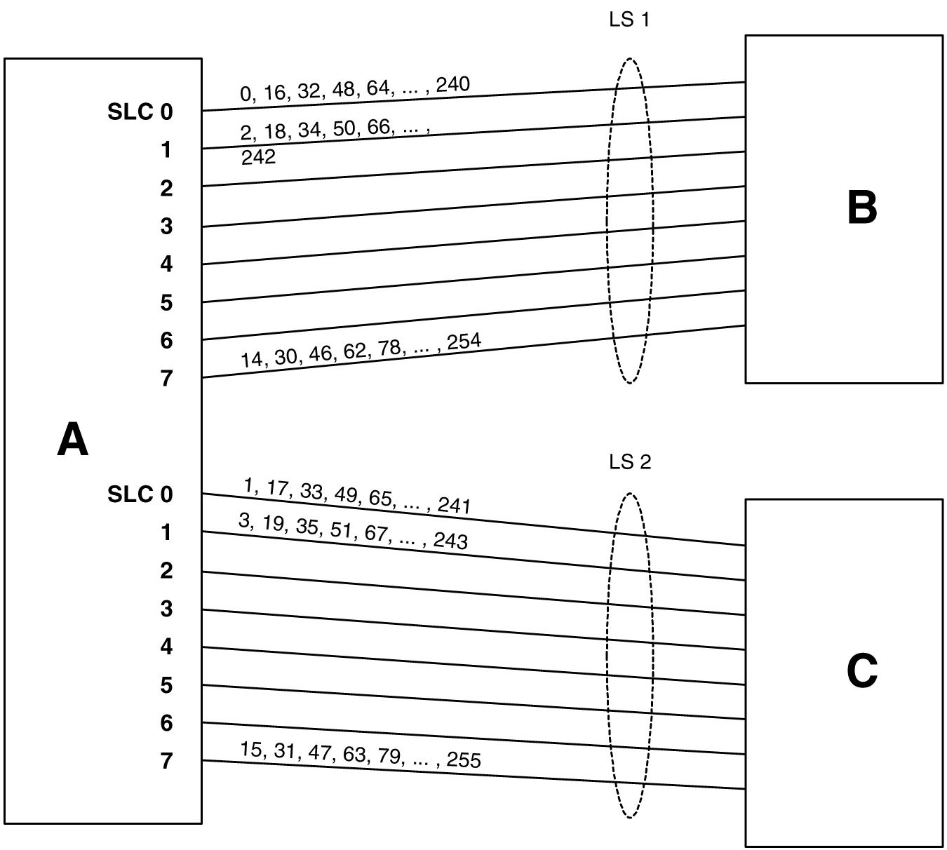
Figure 3-33 shows the mapping for a 4-link single linkset between nodes D and E. When an MSU is to be transmitted, a random 8 bit SLS is generated internally and a link is selected according to this predetermined mapping.

Figure 3-33 Random SLS Mapping to a Single Linkset


img/t_configure_system_random_sls_generation_ss7_config_dbadmin_ss7-fig2.jpg

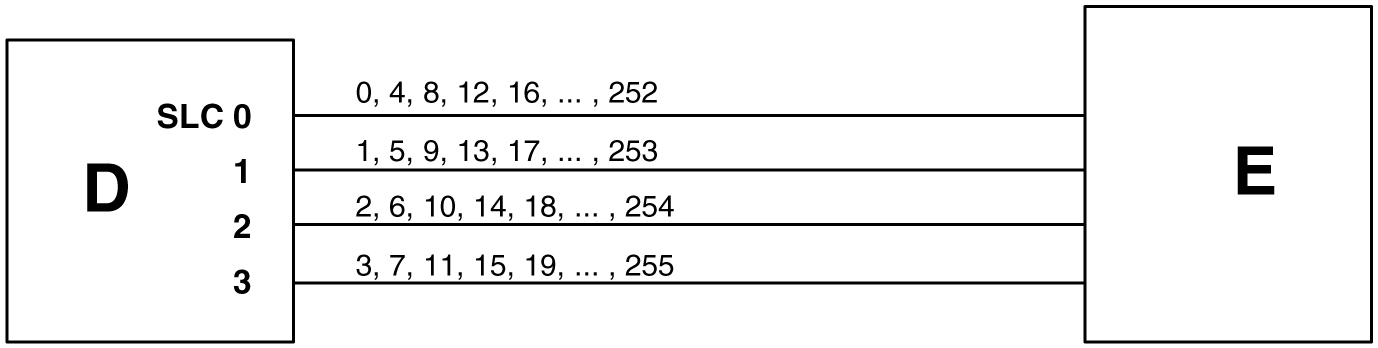
The 4 bit SLS in the outgoing message is equal to the SLS that the EAGLE received. There is no change to the SLS value in the SS7 message.

In a non-failure condition, the process for mapping the internally generated SLS values to SLC (Signaling Link Code) values for specific links is as follows:

  1. A “random” 8-bit SLS value is generated. In reality, a single table of 256 unique SLS values, initially generated in random order, exists in the EAGLE. A counter is maintained for each linkset in the EAGLE that causes the linkset to cycle through the random values in the table as messages are routed out on that linkset. For a combined linkset, the counter for the first linkset in the EAGLE's linkset table is used.
  2. For a combined linkset, the first bit is used to select the linkset and then is ignored when selecting the SLC. For a single linkset, the first bit is used when selecting the SLC. In all cases, the fifth bit is ignored when selecting the SLC. This is due to internal ANSI-based processing in the EAGLE.
  3. The changed SLS value (with fifth and possibly also first bits ignored) is then divided by the number of links in the linkset (not a combined linkset) and the remainder gives the SLC value. For example, in Figure 3-32, the SLS value 78 is mapped to SLC 7 in linkset LS1 as follows:
    1. The binary equivalent for decimal number 78 is 01001110.
    2. The fifth bit is ignored leaving the binary number 0101110.
    3. The least significant bit is used to select linkset LS1 and is then ignored, leaving the binary number 010111.
    4. The decimal equivalent of the binary number 010111 is 23. When the number 23 is divided by the number of links in the linkset, in this example, eight, a remainder of seven remains, thus SLC 7 on linkset LS1 is chosen for the outgoing message.

    In the example shown in Figure 3-33, the SLS value 78 is mapped to SLC 2 in LS1 (the only linkset) as follows:

    1. The binary equivalent for decimal number 78 is 01001110.
    2. The fifth bit is ignored leaving the binary number 0101110.
    3. The decimal equivalent of the binary number 0101110 is 46. When the number 46 is divided by the number of links in the linkset, in this example, four, a remainder of two remains, thus SLC 2 on linkset LS1 is chosen for the outgoing message.

      Table 3-25 shows the mapping for a combined linkset with 16 links in each linkset. This table is discussed in more detail in the next section.

Link failure scenarios

In any situation where a link is failed, SLS values that were mapped to that link are remapped to other links of the linkset or combined linkset. This is done in the reverse order that the SLS values were originally mapped to links, of course skipping the failed link. Subsequent link failures will have their SLS values, along with SLS values from the prior failures, remapped in the same way. The odd/even mapping rule for combined linksets does not apply to the remapped SLS values under failure conditions. This is to continue to achieve the best possible load balance across all links. No MSUs should be discarded in any case.

For example, Table 3-25 shows how the internal 8-bit SLS values are distributed for a combined linkset with 16 links per linkset. It also shows what happens when one or two of the links fail. As this example shows, the SLS values that are identical after the fifth bit is dropped (for example, 0 and 16, 192 and 208, etc.) are remapped to the same link. This is why in this example the 8 different SLS values from the first failed link are remapped to only 4 links and not 8.

Table 3-25 Failure Scenarios for a 32-Link Combined Linkset

Linkset/SLC Normal SLS Mapping SLS Mapping for Single Link Failure SLS Mapping for Dual Link Failure

LS1/0

0 16 64 80 128 144 192 208

Failed

Failed

LS1/1

2 18 66 82 130 146 194 210

Same as Normal SLS Mapping

Same as Normal SLS Mapping

LS1/7

14 30 78 94 142 158 206 222

Same as Normal SLS Mapping

Same as Normal SLS Mapping

LS1/8

32 48 96 112 160 176 224 240

Same as Normal SLS Mapping

Same as Normal SLS Mapping

LS1/9

34 50 98 114 162 178 226 242

Same as Normal SLS Mapping

Same as Normal SLS Mapping

LS1/12

40 56 104 120 168 184 232 248

Same as Normal SLS Mapping

40 56 … 248 225 241

LS1/13

42 58 106 122 170 186 234 250

Same as Normal SLS Mapping

42 58 … 250 161 177

LS1/14

44 60 108 124 172 188 236 252

44 60 … 252 192 208

44 60 … 252 97 113

LS1/15

46 62 110 126 174 190 238 254

46 62 … 254 64 80

46 62 … 254 33 49


LS2/0

1 17 65 81 129 145 193 208

Same as Normal SLS Mapping

Same as Normal SLS Mapping

LS2/7

15 31 79 95 143 159 207 223

Same as Normal SLS Mapping

Same as Normal SLS Mapping

LS2/8

33 49 97 113 161 177 225 241

Same as Normal SLS Mapping

Failed

LS2/12

41 57 105 121 169 185 233 249

Same as Normal SLS Mapping

41 57 … 249 192 208

LS2/13

43 59 107 123 171 187 235 251

Same as Normal SLS Mapping

43 59 … 251 128 144

LS2/14

45 61 109 125 173 189 237 253

45 61 … 253 128 144

45 61 … 253 64 80

LS2/15

47 63 111 127 175 191 239 255

47 63 … 255 0 16

47 63 … 255 0 16

Because of the large number of internal SLS values being remapped across the relatively small number of links, traffic is essentially evenly distributed across the remaining links. This is true in all cases, regardless of the original number of links or the number of failed links.

  1. Display the existing values for the randsls parameter by entering the rtrv-stpopts command. The value for the randsls parameter is shown in the RANDSLS field. This is an example of the possible output.
    
    rlghncxa03w 06-10-17 16:02:05 GMT  EAGLE5 36.0.0
    STP OPTIONS
    -----------------------
    RANDSLS          class0
    

    Note:

    The rtrv-stpopts command output contains other fields that are not used by this procedure. If you wish to see all the fields displayed by the rtrv-stpopts command, see the rtrv-stpopts command description in Commands User's Guide.

    If the randsls=all parameter will not be specified with the chg-stpopts command, continue the procedure with 5.

    If the randsls=all parameter will be specified with the chg-stpopts command, continue the procedure with 2.

  2. Verify the value of the class1seq parameter of the chg-sccpopts command by entering the rtrv-sccpopts command. This is an example of the possible output.
    
    rlghncxa03w 06-10-17 16:02:05 GMT  EAGLE5 36.0.0
    
    SCCP OPTIONS
    ---------------------------
    CLASS1SEQ                on
    

    If the value of the class1seq parameter is on, the randsls=all parameter of the chg-stpopts command should not be used. The class1seq=on parameter allows UDT/XUDT Class 1 ITU messages to be delivered to the remote node in the order that they were received. Using the randsls=all parameter with the class1seq=on parameter does not guarantee that UDT/XUDT Class1 ITU messages are delivered to the remote node in the order that they were received.

    If you wish to continue delivering UDT/XUDT Class 1 ITU messages to the remote node in the order that they were received, or if the value of the class1seq parameter of the chg-sccpopts command is off, continue the procedure with 5.

    If you do not wish to continue delivering UDT/XUDT Class 1 ITU messages to the remote node in the order that they were received, continue the procedure with 3.

  3. Change the value of the class1seq parameter of the chg-sccpopts command by entering this command.

    chg-sccpopts:class1seq=off

    When this command has successfully completed, this message should appear.

    
    rlghncxa03w 06-10-07 00:22:57 GMT  EAGLE5 36.0.0
    CHG-SCCPOPTS: MASP A - COMPLTD
    
  4. Verify the changes by entering the rtrv-sccpopts command. This is an example of the possible output.
    
    rlghncxa03w 08-12-17 16:02:05 GMT  EAGLE5 40.0.0
    
    SCCP OPTIONS
    ---------------------------
    CLASS1SEQ               off
    
  5. Change the randsls parameter value. For this example, enter this command.

    chg-stpopts:randsls=all

    When this command has successfully completed, this message should appear.

    
    rlghncxa03w 06-10-07 00:22:57 GMT  EAGLE5 36.0.0
    CHG-STPOPTS: MASP A - COMPLTD
    
  6. Verify the changes using the rtrv-stpopts command. This is an example of the possible output.
    
    rlghncxa03w 06-10-17 16:02:05 GMT  EAGLE5 36.0.0
    STP OPTIONS
    -----------------------
    RANDSLS             all
    

    Note:

    The rtrv-stpopts command output contains other fields that are not used by this procedure. If you wish to see all the fields displayed by the rtrv-stpopts command, see the rtrv-stpopts command description in Commands User's Guide.

    If the randsls parameter value is off, all, or class0, continue the procedure with 10.

    If the randsls parameter value is perls, continue the procedure by performing one of these steps.
    • If Random SLS will not be applied to ANSI linksets, continue the procedure with 10.
    • If Random SLS will be applied to ANSI linksets, continue the procedure with 7.
  7. Verify the value of the slsreplace parameter by entering the rtrv-ss7opts command. This is an example of the possible output.
    
    rlghncxa03w 08-12-17 16:02:05 GMT  EAGLE5 40.0.0
    
    SS7 OPTIONS
    -----------------------
    SLSREPLACE   no
    

    Note:

    The rtrv-ss7opts command output contains other fields that are not used by this procedure. If you wish to see all the fields displayed by the rtrv-ss7opts command, see the rtrv-ss7opts command description in Commands User's Guide.

    If the slsreplace parameter value is yes, continue the procedure with 10.

    If the slsreplace parameter value is no, continue the procedure with 8.

  8. Change the slsreplace parameter value. For this example, enter this command.

    chg-ss7opts:slsreplace=yes

    When this command has successfully completed, this message should appear.

    
    rlghncxa03w 08-12-07 00:22:57 GMT  EAGLE5 40.0.0
    CHG-SS7OPTS: MASP A - COMPLTD
    
  9. Verify the changes using the rtrv-ss7opts command. This is an example of the possible output.
    
    rlghncxa03w 08-12-17 16:02:05 GMT  EAGLE5 40.0.0
    
    SS7 OPTIONS
    -----------------------
    SLSREPLACE   yes
    

    Note:

    The rtrv-ss7opts command output contains other fields that are not used by this procedure. If you wish to see all the fields displayed by the rtrv-ss7opts command, see the rtrv-ss7opts command description in Commands User's Guide.
  10. Back up the new changes using the chg-db:action=backup:dest=fixed command. These messages should appear, the active Maintenance and Administration Subsystem Processor (MASP) appears first.
    
    BACKUP (FIXED) : MASP A - Backup starts on active MASP.
    BACKUP (FIXED) : MASP A - Backup on active MASP to fixed disk complete.
    BACKUP (FIXED) : MASP A - Backup starts on standby MASP.
    BACKUP (FIXED) : MASP A - Backup on standby MASP to fixed disk complete.
    

Figure 3-34 Configuring the System for Random SLS Generation


Sheet 1 of 3


Sheet 2 of 3


Sheet 3 of 3

Configuring the Options for the TDM Global Timing Interface

This procedure is used to configure the options for the TDM Global Timing Interface using the chg-clkopts command with the following parameters.

:clock - the clock that is being updated. This parameter has three values.
  • primary - the primary clock
  • secondary - the secondary clock
  • all - both the primary and secondary clocks

:hsclksrc – the source of the high-speed master clock.

  • rs422T1 (1544 KHz) or E1 (2048 KHz) RS-422 clock interface
  • t1framedT1 framed clocking as defined in ANSIT1.101, Synchronization Interface Standard, 1999.
  • t1unframedT1 unframed clocking as defined in ANSIT1.102, Digital Hierarchy Electrical Signals, 1987.
  • e1framedE1 framed clocking as defined in section 9 of ITU-T Recommendation G.703, Physical/Electrical Characteristics of Hierarchical Digital Interfaces, October 1998.
  • e1unframedE1 unframed clocking as defined in section 13 of ITU-T Recommendation G.703, Physical/Electrical Characteristics of Hierarchical Digital Interfaces, October 1998.

:hsclkll – sets the gain of the LIU (line interface unit) of the TDM when the hsclksrc parameter value is either t1framed, t1unframed, e1framed, or e1unframed.

  • longhaul – high gain for the LIU
  • shorthaul – low gain for the LIU

Caution:

Changing these options changes the external master clock source for all E1, T1, ANSIATM, or E1ATM high-speed signaling links using external timing.

:force - allows the hsclksrc parameter to be changed if the status of the high-speed clocks is valid. The force parameter must be specified when the EAGLE contains valid high-speed clocks. The force parameter can be specified only if the hsclksrc parameter is specified. The force parameter has only one value - yes. The status of the high-speed clocks is shown by the rept-stat-clk command.

When the EAGLE is delivered to the user, the values of the hsclksrc and hsclkll parameters are set to these values:

  • hsclksrcrs422
  • hsclklllonghaul

Either of these values can be changed only if the part number of both TDMs in card locations 1114 and 1116 is 870-0774-15 or later. If the part numbers of the TDMs are not correct, the TDMs with the incorrect part numbers must be replaced with TDM part number 870-0774-15 or later. If the TDM is being replaced with the E5-TDMs, the GPSM-II cards in card locations 1113 and 1115 and the TDMs in card locations 1114 and 1116 must be replaced with E5-MASP cards.

Caution:

Contact the Customer Care Center, Refer to My Oracle Support (MOS) for the contact information, before replacing the TDMs.

If the EAGLE does not contain LIMDS0 cards, but contains TDM part numbers 870-0774-15 or later, the clock source for the TSC (Time Slot Counter) synchronization feature used by the EAGLE 5 Integrated Monitoring Support feature can be generated from the high-speed master clock source. An external BITS clock is not required.

If an external BITS clock is connected to a EAGLE without LIMDS0 cards, but with TDM part numbers 870-0774-15 or later, the external BITS clock is used as the clock source for the TSC (Time Slot Counter) synchronization feature. If the external BITS clock fails, the clock source for the TSC synchronization feature is generated from the high-speed master clock source.

If LIMDS0 cards are present in the EAGLE, the external BITS clock is required for timing of the DS0 signaling links and for TSC (Time Slot Counter) synchronization used by the Integrated Sentinel . If the EAGLE also contains TDM part numbers 870-0774-15 or later along with the LIMDS0 cards, this procedure can be used to select the source of the high-speed master clock for the high-speed links using external timing. The high-speed master clock source cannot be used to generate the clock source for any low-speed links and for the TSC (Time Slot Counter) synchronization feature.

  1. Display the existing values for the hsclksrc and hsclkll parameters by entering the rtrv-clkopts command.

    The value for the hsclksrc and hsclkll parameters is shown in the HSCLKSRC and HSCLKLL fields. This is an example of the possible output.

    
    rlghncxa03w 09-02-17 16:02:05 GMT  EAGLE5 40.1.0
    CLK OPTIONS
    -----------------------
    
    PRIMARY
    -----------------------
    HSCLKSRC          rs422
    HSCLKLL        longhaul
    
    SECONDARY
    -----------------------
    HSCLKSRC          rs422
    HSCLKLL        longhaul
    

    If either the HSCLKSRC or HSCLKLL values in this step are not the system default values for these parameters (HSCLKSRC - RS422, HSCLKLL - LONGHAUL), continue this procedure with 3.

    If the HSCLKSRC and HSCLKLL values in this step are the system default values for these parameters, continue this procedure with 2.

  2. Visually verify the part numbers of the TDMs in card location 1114 and 1116.

    To change these options, the part number of both TDMs must be 870-0774-15 or later. If the part number of one or both TDMs is not 870-0774-15 or later, the TDM with the incorrect part number must be replaced with TDMs with the correct part number.

    Caution:

    Refer to My Oracle Support (MOS) before replacing the TDMs.
  3. Verify the status of the high-speed clocks by entering the rept-stat-clk command.

    This is an example of the possible output.

    
    rlghncxa03w 08-06-01 11:34:04 GMT  EAGLE5 39.0.0
    COMPOSITE                              PST           SST       AST
        SYSTEM CLOCK                       IS-NR         Active    -----
    ALARM STATUS = No Alarms.
        Primary Comp Clk 1114   (CLK A)    IS-NR         Active    -----
        Primary Comp Clk 1116   (CLK B)    IS-NR         Active    -----
        Secondary Comp Clk 1114 (CLK A)    IS-NR         Idle      -----
        Secondary Comp Clk 1116 (CLK B)    IS-NR         Idle      -----
    
    Clock      Using         Bad
    CLK A        9            0
    CLK B        0            0
    CLK I        0            --
    
    HIGH SPEED                             PST           SST       AST
        SYSTEM CLOCK                       IS-NR         Idle      -----
    ALARM STATUS = No Alarms.
        Primary HS Clk 1114    (HS CLK A)  IS-NR         Active    -----
        Primary HS Clk 1116    (HS CLK B)  IS-NR         Active    -----
        Secondary HS Clk 1114  (HS CLK A)  IS-NR         Idle      -----
        Secondary HS Clk 1116  (HS CLK B)  IS-NR         Idle      -----
    
    HS CLK TYPE 1114     = RS422
    HS CLK LINELEN 1114  = LONGHAUL
    HS CLK TYPE 1116     = RS422
    HS CLK LINELEN 1116  = LONGHAUL
    
    Clock      Using         Bad
    HS CLK A     2            0
    HS CLK B     0            0
    HS CLK I     0            --
     
    Command Completed
    

    If the rept-stat-clk output does not show any high-speed clocks ( HIGH SPEED SYSTEM CLOCK , Primary HS Clk , Secondary HS Clk , HS CLK TYPE, and HS CLK LINELEN fields), the EAGLE does not contain any cards that are capable of using high-speed master timing.

  4. Change either the hsclksrc or hsclkll parameter values, or both parameter values.

    To change the primary and secondary clocks, for this example, enter this command.

    chg-clkopts:clock=all:hsclksrc=t1unframed:hsclkll=shorthaul:force=yes

    To change only the primary clock, for this example, enter this command.

    chg-clkopts:clock=primary:hsclksrc=t1unframed:hsclkll=shorthaul:force=yes

    To change only the secondary clock, for this example, enter this command.

    chg-clkopts:clock=secondary:hsclksrc=t1unframed:hsclkll=shorthaul:force=yes

    The clock=primary and clock=secondary parameters can be specified only if the EAGLE contains E5-MASP cards.

    Note:

    If the rept-stat-clk output in 3 shows valid high-speed clocks, and the hsclksrc parameter is specified with the chg-clkopts command, the force=yes parameter must be specified with the chg-clkopts command.

    Caution:

    Changing these options changes the external master clock source for all E1, T1, ANSIATM, or E1ATM high-speed signaling links using external timing. A clock outage can occur and traffic on these signaling links can be lost if the new source clock type does not match the source clock that these signaling links are actually using.

    When this command has successfully completed, this message should appear.

    
    rlghncxa03w 09-02-07 00:22:57 GMT  EAGLE5 40.1.0
    CHG-CLKOPTS: MASP A - COMPLTD
    
  5. Verify the changes using the rtrv-clkopts command.

    This is an example of the possible output.

    
    rlghncxa03w 09-02-17 16:02:05 GMT  EAGLE5 40.1.0
    CLK OPTIONS
    -----------------------
    
    PRIMARY
    -----------------------
    HSCLKSRC     t1unframed
    HSCLKLL       shorthaul
    
    SECONDARY
    -----------------------
    HSCLKSRC     t1unframed
    HSCLKLL       shorthaul
    
  6. Back up the new changes using the chg-db:action=backup:dest=fixed command.

    These messages should appear, the active Maintenance and Administration Subsystem Processor (MASP) appears first.

    
    BACKUP (FIXED) : MASP A - Backup starts on active MASP.
    BACKUP (FIXED) : MASP A - Backup on active MASP to fixed disk complete.
    BACKUP (FIXED) : MASP A - Backup starts on standby MASP.
    BACKUP (FIXED) : MASP A - Backup on standby MASP to fixed disk complete.
    

Figure 3-35 Configuring the Options for the TDM Global Timing Interface


Sheet 1 of 2


Sheet 2 of 2

Configuring the Restricted Linkset Option

This procedure is used to configure the restricted linkset option using the chg-ss7opts command with the lsrestrict parameter. The lsrestrict parameter has two values:

  • on – enables the lsrestrict option
  • off – disables the lsrestrict option.

When a large linkset (a linkset containing more than three links) first becomes available, there may not be enough available links to carry the normal amount of traffic on the linkset. The EAGLE sends response method TFA/TFRs when the number of links within a linkset, specified by the tfatcabmlq parameter for that linkset, are active and available to carry traffic. This was designed to prevent congestion on the newly available linksets. Internally in the EAGLE, if a single link within a lower cost route is active, the EAGLE attempts to route traffic over the lower cost route. If no traffic or small amounts of traffic are arriving due to the issuance of a TFR, then no congestion should occur.

However, this behavior applies only to traffic destined for remote nodes and not to traffic destined for the EAGLE itself. Typically, messages that are global title routed are destined for the EAGLE's true, secondary or capability point code. The existing congestion prevention mechanism does not prevent traffic destined for EAGLE to be controlled by the linkset’s tfatcabmlq parameter. This is because TFx messages have an affected point code field that is the far end destination point code and not the EAGLE's point code, so traffic destined for EAGLE continues to arrive for the restricted destination. It is not feasible to place EAGLE's point code in the affected destination field as this would affect all traffic destined for EAGLE and not just traffic over a specific route.

With the lsrestrict=off option, the EAGLE continues to route traffic in this manner.

The lsrestrict=on option enhances the EAGLE’s existing behavior of the linkset’s tfatcabmlq parameter and allow the state of the route combined with the cost value of the route to determine the preferred route to use.

Turning the lsrestrict option on changes the way the EAGLE routes messages by using the state of the route along with the cost of the route to determine the preferred route to use. With this option on, the preferred route is not the absolute lowest cost available route in the routeset. A route is considered available if its status is either Allowed or Restricted. If the state of the absolute lowest cost route in the routeset is Restricted, the preferred route is the lowest cost route in the routeset whose status is Allowed. Make sure that you wish to have the EAGLE route messages in this manner before turning the lsrestrict option on.

In previous releases, a C linkset's tfatcabmlq parameter is not configurable and set to 1 (the linkset is allowed when the first link is available). This is because the C linkset is designed for message trafficking between the mate STP's and would allow these messages to be transferred as soon as the first link in the C linkset was available. The lsrestrict=on option allows the tfatcabmlq parameter value for a C linkset to be from 0 to 16, just as any other linkset.

With the lsrestrict=off option, the tfatcabmlq parameter value for a C linkset is set to 1 and cannot be changed.

When a linkset that was previously prohibited becomes restricted (that is, the number of links that became available is less than the required number of links as specified by the linkset’s tfatcabmlq parameter) the following events occur when the lsrestrict option is on:

  1. The EAGLE 5 ISS does not broadcast TFAs.
  2. Point codes that were previously prohibited and use the linkset as a lower cost route are marked restricted. The EAGLE continues to broadcast TFRs.
  3. Point codes that were previously restricted and use the linkset as a least cost route remain restricted. The EAGLE does not broadcast any TFx message. For these point codes, RSRT will respond to RSP messages with a TFR, and will not respond to RSR messages.
  4. The EAGLE marks the linkset as restricted.
  5. If a higher cost route is available, the EAGLE routes the traffic over the higher cost route.

Once the required number of links are available for the linkset, the following events occur when the lsrestrict option is on:

  1. The EAGLE marks the previously prohibited/restricted point codes as allowed that use the linkset as a lower cost route (unless the point code's nonadjacent status is prohibited).
  2. The EAGLE does not broadcast TFAs for the newly allowed point codes, but responds to RSR/RSP messages with a TFA.
  3. The EAGLE marks the linkset as allowed. The appropriate changeback procedures are performed and traffic is processed normally.

Canceling the RTRV-LS Command

Because the rtrv-ls command used in this procedure can output information for a long period of time, the rtrv-ls command can be canceled and the output to the terminal stopped. There are three ways that the rtrv-ls command can be canceled.

  • Press the F9 function key on the keyboard at the terminal where the rtrv-ls command was entered.
  • Enter the canc-cmd without the trm parameter at the terminal where the rtrv-ls command was entered.
  • Enter the canc-cmd:trm=<xx>, where <xx> is the terminal where the rtrv-ls command was entered, from another terminal other that the terminal where the rtrv-ls command was entered. To enter the canc-cmd:trm=<xx> command, the terminal must allow Security Administration commands to be entered from it and the user must be allowed to enter Security Administration commands. The terminal’s permissions can be verified with the rtrv-secu-trm command. The user’s permissions can be verified with the rtrv-user or rtrv-secu-user commands.

For more information about the canc-cmd command, go to Commands User's Guide.

  1. Display the existing value for the lsrestrict parameter by entering the rtrv-ss7opts command. This is an example of the possible output.
    
    rlghncxa03w 06-10-17 16:02:05 GMT  EAGLE5 36.0.0
    
    SS7 OPTIONS
    -----------------------
    LSRESTRICT          off
    

    Note:

    The rtrv-ss7opts command output contains other fields that are not used by this procedure. If you wish to see all the fields displayed by the rtrv-ss7opts command, see the rtrv-ss7opts command description in Commands User's Guide.

    Note:

    If the lsrestrict parameter value in step 1 is off, skip steps 2 and 3, and go to step 4.
  2. Display the linksets in the database by entering the rtrv-ls command. This is an example of the possible output.
    
    rlghncxa03w 06-10-10 11:43:04 GMT EAGLE5 36.0.0
                                     L3T SLT              GWS GWS GWS
    LSN          APCA   (SS7)  SCRN  SET SET BEI LST LNKS ACT MES DIS SLSCI NIS
    e1e2         001-207-000   none  1   1   no  B   6    off off off no    off
    ls05         002-009-003   scr2  1   1   no  C   4    on  off on  no    off
    ls1305       000-005-000   none  1   1   no  A   1    off off off no    off
    ls1307       000-007-000   none  1   1   no  A   1    off off off no    off
    e1m1s1       001-001-001   none  1   1   no  A   7    off off off no    off
    e1m1s2       001-001-002   none  1   1   no  A   7    off off off no    off
    
                                     L3T SLT              GWS GWS GWS
    LSN          APCI   (SS7)  SCRN  SET SET BEI LST LNKS ACT MES DIS SLSCI NIS
    e1e2i        1-207-0       none  1   1   no  B   4    off off off ---   on
    ls1315       0-015-0       none  1   1   no  A   1    off off off ---   off
    ls1317       0-017-0       none  1   1   no  A   1    off off off ---   on
    e1m2s1       1-011-1       none  1   1   no  A   7    off off off ---   off
    e1m2s2       1-011-2       none  1   1   no  A   7    off off off ---   off
    
    Link set table is (11 of 1024) 1% full.
    

    Note:

    If there are no C linksets (linksets with the value C in the LST column) shown in the rtrv-ls output in step 2, skip step 3 and go to step 4.
  3. Change the tfatcabmlq parameter value for one of the C linksets shown in step 2 to 0 using the chg-ls command. For this example, enter this command.

    chg-ls:lsn=ls05:tfatcabmlq=0

    When this command has successfully completed, this message should appear.

    
    rlghncxa03w 06-10-07  08:38:45 GMT  EAGLE5 36.0.0
    Link set table is ( 11 of 1024)  1% full
    CHG-LS:  MASP A - COMPLTD
    

    After the chg-ls command has been performed, repeat step 3 with the name of another C linkset shown in step 2.

    When all the C linksets have been changed, go to step 4.

    Note:

    When the tfatcabmlq parameter is set to 0, its value in the rtrv-ls:lsn=<linkset name> output is shown as 1/2 of the number of signaling links contained in the linkset.
  4. Change the value of the lsrestrict parameter.

    If the current value of the lsrestrict parameter is off, enter this command.

    chg-ss7opts:lsrestrict=on

    If the current value of the lsrestrict parameter is on, enter this command.

    chg-ss7opts:lsrestrict=off

    When this command has successfully completed, this message should appear.

    
    rlghncxa03w 06-10-07 00:22:57 GMT  EAGLE5 36.0.0
    CHG-SS7OPTS: MASP A - COMPLTD
    

    Caution:

    Turning the lsrestrict option on changes the way the EAGLE routes messages by using the state of the route along with the cost of the route to determine the preferred route to use. With this option on, the preferred route is not the absolute lowest cost available route in the routeset. A route is considered available if its status is either Allowed or Restricted. If the state of the absolute lowest cost route in the routeset is Restricted, the preferred route is the lowest cost route in the routeset whose status is Allowed. Make sure that you wish to have the EAGLE route messages in this manner before turning the lsrestrict option on.
  5. Verify the changes using the rtrv-ss7opts command. This is an example of the possible output.
    
    rlghncxa03w 06-10-17 16:02:05 GMT  EAGLE5 36.0.0
    
    SS7 OPTIONS
    -----------------------
    LSRESTRICT          on
    

    Note:

    The rtrv-ss7opts command output contains other fields that are not used by this procedure. If you wish to see all the fields displayed by the rtrv-ss7opts command, see the rtrv-ss7opts command description in Commands User's Guide.
  6. Back up the new changes using the chg-db:action=backup:dest=fixed command. These messages should appear, the active Maintenance and Administration Subsystem Processor (MASP) appears first.
    
    BACKUP (FIXED) : MASP A - Backup starts on active MASP.
    BACKUP (FIXED) : MASP A - Backup on active MASP to fixed disk complete.
    BACKUP (FIXED) : MASP A - Backup starts on standby MASP.
    BACKUP (FIXED) : MASP A - Backup on standby MASP to fixed disk complete.
    

Figure 3-36 Configuring the Restricted Linkset Option


Sheet 1 of 2


Sheet 2 of 2

Configuring the Options for Handling TFCs on ITU-I and ITU-N Networks

This procedure is used to configure the options for handling TFCs on ITU-I and ITU-N networks using the chg-ss7opts command with these two parameters:

:discardtfci – This parameter specifies that the EAGLE 5 ISS discards TFC traffic received from an ITU-I network (discardtfci=on), or does not discard TFC traffic received from an ITU-I network (discardtfci=off). The system default value for this parameter is off.

:discardtfcn – This parameter specifies that the EAGLE 5 ISS discards TFC traffic received from an ITU-N network (discardtfcn=on), or does not discard TFC traffic received from an ITU-N network (discardtfcn=off). The system default value for this parameter is off.

  1. Display the existing values for the discardtfci and discardtfcn parameters by entering the rtrv-ss7opts command.

    This is an example of the possible output.

    
    rlghncxa03w 06-10-17 16:02:05 GMT  EAGLE5 36.0.0
    SS7 OPTIONS
    -----------------------
    DISCARDTFCI         off
    DISCARDTFCN         off
    

    Note:

    The rtrv-ss7opts command output contains other fields that are not used by this procedure. If you wish to see all the fields displayed by the rtrv-ss7opts command, see the rtrv-ss7opts command description in the Commands Manual.
  2. Change the value of the discardtfci and discardtfcn parameters.

    The values of these parameters is either on or off. The value specified in this step cannot be the same as the value shown in step 1.

    If you wish to change the value of the discardtfci parameter, specify the discardtfci parameter with the chg-ss7opts command. For this example, enter this command.

    chg-ss7opts:discardtfci=on

    If you wish to change the value of the discardtfcn parameter, specify the discardtfcn parameter with the chg-ss7opts command. For this example, enter this command.

    chg-ss7opts:discardtfcn=on

    If you wish to change the value of both the discardtfci and discardtfcn parameters, specify the discardtfci and discardtfcn parameters with the chg-ss7opts command. For this example, enter this command.

    chg-ss7opts:discardtfci=on:discardtfcn=on

    When this command has successfully completed, this message should appear.

    
    rlghncxa03w 06-10-07 00:22:57 GMT  EAGLE5 36.0.0
    CHG-SS7OPTS: MASP A - COMPLTD
    
  3. Verify the changes using the rtrv-ss7opts command.

    This is an example of the possible output.

    
    rlghncxa03w 06-10-17 16:02:05 GMT  EAGLE5 36.0.0
    SS7 OPTIONS
    -----------------------
    DISCARDTFCI          on
    DISCARDTFCN          on
    

    Note:

    The rtrv-ss7opts command output contains other fields that are not used by this procedure. If you wish to see all the fields displayed by the rtrv-ss7opts command, see the rtrv-ss7opts command description in the Commands Manual.
  4. Back up the new changes using the chg-db:action=backup:dest=fixed command.

    These messages should appear, the active Maintenance and Administration Subsystem Processor (MASP) appears first.

    
    BACKUP (FIXED) : MASP A - Backup starts on active MASP.
    BACKUP (FIXED) : MASP A - Backup on active MASP to fixed disk complete.
    BACKUP (FIXED) : MASP A - Backup starts on standby MASP.
    BACKUP (FIXED) : MASP A - Backup on standby MASP to fixed disk complete.


Figure 3-37 Configuring the Options for Handling TFCs on ITU-I and ITU-N Networks


Changing the High-Capacity Card Temperature Alarm Thresholds

This procedure is used to change the temperature alarm thresholds for high-capacity cards (shown in Table 3-26) using the chg-th-alm command and these parameters.

:thermallv1 – The temperature threshold, specified as a percentage of the card’s thermal shutdown temperature, at which major alarm UAM 0078 is generated. UAM 0078 is generated to alert the user that corrective action needs to be performed to prevent the high-capacity cards from overheating. If the high-capacity card is E5-STC, E5-SM4G, E5-TSM, or E5-MCPM-B, the state of the card is not changed. If the high-capacity card is an HC MIM, E5-E1T1, E5-ENET card, or E5-ATM card, or SLIC, the state of the card is changed to IS-ANR (in service-abnormal).

For the following cards, these actions occur when thermallv1 temperature threshold is reached:
E5-ENET-B running ERTHC GPL
Alarm raised; no additional actions.
E5-ATM-B running ATMHC GPL
Alarm raised. PST/SST of card transitions to IS-ANR/Restrict.
E5-ENET-B running IPSHC GPL
Alarm raised; no additional actions. .
E5-ENET-B running IPSG GPL
Alarm raised; no additional actions.
E5-ENET-B running IPLIMx/IPGWx GPL
Alarm raised; no additional actions.
E5-MCPM-B running MCPHC GPL
Alarm raised; no additional actions.

The values for this parameter are 73 to 92. The system default value for this parameter is 92.

:thermallv2 – The temperature threshold, specified as a percentage of the card’s maximum operating temperature, at which critical alarm UAM 0077 is generated. When this threshold is reached, the high-capacity cards shed their traffic load, accept no more traffic, and the state of the cards is changed to IS-ANR (in service-abnormal). The values for this parameter are 74 to 100. The system default value for this parameter is 100.

For EPM-B cards, when the thermallv1 temperature threshold is reached, critical alarm 0077 is raised and the following additional actions occur:
E5-ENET-B or SLIC running ERTHC GPL
Outstanding grant requests will be completed but no new grant requests will be accepted. The card's state transitions “in-service abnormal.”
E5-ATM-B running ATMHC GPL
PST/SST of card remains IS-ANR/Restrict.
E5-ENET-B or SLIC running IPSHC GPL
Auto inhibits all telnet terminals allowed by user on that card and sets their status to OOS-MT-DSBLD/MEA. Sets card state to out-of-service, maintenance fault.
E5-ENET-B or SLIC running IPSG GPL
Outstanding grant requests will be completed but no new grant requests will be accepted.
E5-ENET-B running IPLIMx/IPGWx GPL
Outstanding grant requests will be completed but no new grant requests will be accepted.
E5-MCPM-B or SLIC running MCPHC GPL
PST/SST of card transitions to IS-ANR/Restrict . If card is primary MCP, role change arbitration is initiated.

For more information on UAM 0078 and UAM 077, go to Unsolicited Alarm and Information Messages Reference.

Table 3-26 shows the maximum thermal operating limit of temperatures of these cards at selected threshold levels.

Table 3-26 High Capacity Thermal Limits

High Capacity Card High Capacity Card's Temperature at the Maximum Thermal Operating Limit (thermallv2 = 100%) High Capacity Card Temperatures at Selected Threshold Levels
95% 90% 85% 80% 75%
HC-MIM

82° C

179.6° F

77.9° C

172.2° F

73.8° C

164.8° F

69.7° C

157.5° F

65.6° C

150.1° F

61.5° C

147.2° F

E5-ENET

E5-E1T1

E5-STC

E5-TSM

E5-ATM

95° C

203° F

90.25° C

194.5° F

85.5° C

185.9° F

80.75° C

177.4° F

76° C

168.8° F

71.25° C

160.3° F

E5-SM4G

E5-MASP

E5-ENET-B

E5-ATM-B

E5-SM8G-B

E5-MCPM-B

90° C

194° F

85.5° C

185.9° F

81° C

177.8° F

76.5° C

169.7° F

72° C

161.6° F

67.5 °C

153.5°F

The chg-th-alm command contains other optional parameters. These parameters are not shown here because they are not necessary to provision the high-capacity card temperature alarm thresholds. These parameters are explained in more detail in Commands User's Guide.

  1. Display the current high-capacity card temperature alarm thresholds in the database by entering the rtrv-th-alm command.

    This is an example of the possible output.

    
    rlghncxa03w 06-10-28 09:12:36 GMT EAGLE5 36.0.0
    Thermal Alarm Level 1:               92%
    Thermal Alarm Level 2:               100%
    RTRV-TH-ALM: MASP A - COMPLTD.
    

    Note:

    Thertrv-th-alm command output contains other fields that are not used in this procedure. If you wish to see all the fields displayed by thertrv-th-alm command, see thertrv-th-alm command description in Commands User's Guide.
  2. Change the temperature alarm thresholds by entering the chg-th-alm command with at least one of the temperature alarm threshold parameters.

    The thermallv2 parameter value shown in the rtrv-th-alm output after the chg-th-alm command has been executed must be greater than the thermallv1 parameter value shown in the rtrv-th-alm output.

    If a temperature alarm threshold parameter is not specified with the chg-th-alm command, that parameter value will not be changed. The system default values for the temperature alarm threshold parameters are:

    • :thermallv1 = 92
    • :thermallv2 = 100

    For this example, enter this command.

    chg-th-alm:thermallv1=74:thermallv2=80

    When this command has successfully completed, this message should appear.

    
    rlghncxa03w 06-10-28 09:12:36 GMT EAGLE5 36.0.0
    CHG-TH-ALM: MASP A - COMPLTD
    
  3. Verify the changes using the rtrv-th-alm command.

    This is an example of the possible output.

    
    rlghncxa03w 06-10-28 09:12:36 GMT EAGLE5 36.0.0
    Thermal Alarm Level 1:               70%
    Thermal Alarm Level 2:               80%
    RTRV-TH-ALM: MASP A - COMPLTD.
    

    Note:

    Thertrv-th-alm command output contains other fields that are not used in this procedure. If you wish to see all the fields displayed by thertrv-th-alm command, see thertrv-th-alm command description in Commands User's Guide.
  4. Backup the new changes using the chg-db:action=backup:dest=fixed command.

    These messages should appear, the active Maintenance and Administration Subsystem Processor (MASP) appears first.

    
    BACKUP (FIXED) : MASP A - Backup starts on active MASP.
    BACKUP (FIXED) : MASP A - Backup on active MASP to fixed disk complete.
    BACKUP (FIXED) : MASP A - Backup starts on standby MASP.
    BACKUP (FIXED) : MASP A - Backup on standby MASP to fixed disk complete.
    

Figure 3-38 Changing the High-Capacity Card Temperature Alarm Thresholds


Activating the Origin-Based MTP Routing Feature

This procedure is used to enable and turn on the Origin-Based MTP Routing feature using the feature’s part number and a feature access key.

The feature access key for the Origin-Based MTP Routing feature is based on the feature’s part number and the serial number of the EAGLE, making the feature access key site-specific.

The enable-ctrl-feat command enables the feature by inputting the feature’s access key and the feature’s part number with these parameters:

Note:

As of Release 46.3, the fak parameter is no longer required. This parameter is only used for backward compatibility.

:fak – The feature access key provided by Oracle.

:partnum – The Oracle-issued part number of the Origin-Based MTP Routing feature, 893014201.

Once this feature is enabled, it is permanently enabled. This feature cannot be enabled with a temporary feature access key.

The enable-ctrl-feat command requires that the database contain a valid serial number for the EAGLE, and that this serial number is locked. This can be verified with the rtrv-serial-num command. The EAGLE is shipped with a serial number in the database, but the serial number is not locked. The serial number can be changed, if necessary, and locked once theEAGLE is on-site, with the ent-serial-num command. The ent-serial-num command uses these parameters.

:serial – The serial number assigned to the EAGLE. The serial number is not case sensitive.

:lock – Specifies whether or not the serial number is locked. This parameter has only one value, yes, which locks the serial number. Once the serial number is locked, it cannot be changed.

Note:

To enter and lock the EAGLE’s serial number, the ent-serial-num command must be entered twice, once to add the correct serial number to the database with the serial parameter, then again with the serial and the lock=yes parameters to lock the serial number. You should verify that the serial number in the database is correct before locking the serial number. The serial number can be found on a label affixed to the control shelf (shelf 1100).

The chg-ctrl-feat command uses these parameters:

:partnum – The Oracle-issued part number of the Origin-Based MTP Routing feature, 893014201.

:status=on – used to turn the Origin-Based MTP Routing feature on.

The status of the controlled features in the EAGLE is shown with the rtrv-ctrl-feat command.

To turn the Origin-Based MTP Routing feature on with the chg-ctrl-feat command, the STP option MTPLPRST must be set to yes. This can be verified by performing the rtrv-stpopts command. Perform the Configuring the Frequency of RST Messages on Low Priority Routes procedure to change the MTPLPRST option value, if necessary.

Once the Origin-Based MTP Routing feature is enabled and turned on, provisioning for the Origin-Based MTP Routing feature can be performed. Perform these procedures to provision the Origin-Based MTP Routing feature.

Origin-Based MTP Routing Feature

Origin-Based MTP Routing provides greater flexibility and control over the EAGLE routing mechanisms by enabling the user to selectively route traffic to the same destination through different networks depending on various classes of exception routes. The classes of exception routes are shown in the following list.

  • DPC and OPC - an exception route using the DPC (destination point code) and OPC (originating point code) in the message to determine how the message will be routed.
  • DPC and the originating linkset - an exception route using the DPC and the name of the linkset carrying incoming traffic to the EAGLE to determine how the message will be routed.
  • DPC and CIC - an exception route using the DPC and CIC (circuit identification code) in the message to determine how the message will be routed.
  • DPC and SI - an exception route using the DPC and SI (service indicator) value in the message to determine how the message will be routed.
  • DPC - an exception route using only the DPC in the message to determine how the message will be routed.

The DPC of a route coupled with an exception route class and exception route criteria creates a new destination for the route and also creates an additional entry in the EAGLE’s routing table. The number of entries in the EAGLE’s routing table is the number of DPCs provisioned with the ent-dstn command plus the number of exception route entries provisioned with the ent-rtx command.

The number of entries in the EAGLE’s routing table cannot exceed the number of DPCs allocated in the routing table, shown in the DESTINATION ENTRIES ALLOCATED: row of the rtrv-rtx and rtrv-dstn output. The EAGLE can contain a maximum of 10,000 entries in the routing table. The total number of entries provisioned in the routing table is shown in the TOTAL DPC(s): row of the rtrv-dstn or rtrv-rtx output.

All other properties of a routeset apply to exception routesets with respect to provisioning (routes and route costs) and alarming with the exception of network management, which is discussed in the "Network Management and Exception Routes" section.

Exception Route Processing Order and Route Costs

The processing order of exception routes is pre-defined. The exception class list in the "Network Management and Exception Routes" section also shows the order that the classes of exception routes are processed.

If a particular route has two exception routes, a DPC and OPC and a DPC and CIC exception route, the DPC and OPC exception route is used first since it is processed before the DPC and CIC exception route.

To determine the priority of exception routes, a relative cost value is assigned to each exception route. The relative cost values are used only within an exception route class. The DPC of the exception route contains multiple entries exception route class value, for example multiple entries with the same DPC and OPC value. The relative cost value determines the order in which the exception routes with the same DPC and OPC values are used to route the messages.

For example, DPC A contains the following exception routes:

  • OPC = B: RC=20: LSN=LSB
  • OPC = B: RC=20: LSN=LSC
  • OPC = B: RC=30: LSN=LSD
  • SI = 3: RC=10: LSN=LS3

When an SCCP message is received from Node B, the exception route mechanism splits traffic matching exception routes OPC = B between the linksets LSB and LSC, treating it as a combined linkset, since both entries have the same relative cost value. When both linksets LSB and LSC are not available, traffic is switched to linkset LSD. Even through the SI=3 exception route has a lower relative cost value than the other exception routes for DPC A, the SI=3 exception route is used to route the messages only when the linksets LSB, LSC, and LSD are not available.

CIC Handling

Exception routes can be provisioned based on a single CIC value or a range of CIC values in an ISUP message. The only value used by this feature for all CIC triggers will be the CIC value placed after the routing label and not any CIC value placed within the mandatory fixed, variable or optional parts of the message. Figure 3-39 shows the location of this value within the message.

Figure 3-39 ISDN User Part Message Parts

img/t_activate_origin_based_mtp_routing_feature_ss7_config_dbadmin_ss7-fig1.jpg

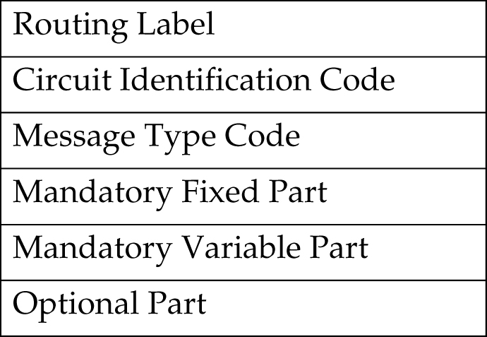
Since this feature will not consider any CIC value placed within the mandatory fixed, variable or optional part, messages within ISUP that are applied over a range of circuits (GRS, CGB, CGU, etc.) may be mishandled. Because of this, the user must consider how maintenance is handled before CIC ranging is used in order to ensure that circuit maintenance is performed properly.

For example, if a GRS is sent where the CIC field is 5 and the range field is 10, this implies that circuits 5 to 15 should be reset. If an exception route is provisioned for CIC 5, it would take the path (if available) provisioned since the CIC value in the message matches the one that is provisioned. However, if the exception route provisioned is 6, the CGU will not take the path provisioned even though 6 is within the range specified by the GRS message.

Network Management and Exception Routes

The Origin-Based MTP Routing operates on an end-to-end scheme, and not a point-to-point scheme. As a result, adjacent point codes cannot have exception routes. Correct network handing is critical for the EAGLE and other routing mechanisms to operate properly. Imposing exception routes over adjacent point codes introduces a large element of risk since elements of the network may receive point code and link events late, impacting routing to those and other destinations.

When considering the impact that exception routing could have on the network, the following restrictions are in place to ensure network sanity:

  • Adjacent point codes cannot not have exception routes.
  • Exception routes do not factor into the status of a destination. A destination’s status is defined only by the standard routes entered.
  • If all the DPC-based routes to a destination are unavailable, then the status of the destination is listed as prohibited even if there are exception routes available.
  • Preventative and broadcast TFx or TCx are not sent based on the status of exception routes. If an exception route is unavailable, the next exception route is chosen ending with the standard provisioned routes.

Congestion Handling and Origin-Based Routing

Since the only identifying characteristic of a TFC message is the capability point code (CPC), the EAGLE is unable to determine if the node or the route used to reach that destination is congested. Normally, the EAGLE would list the destination as congested since there was only one routeset to that destination.

With the Origin-Based MTP Routing feature, there is no longer only one routeset to a destination, but many. However, due to the inexact nature of the TFC, the EAGLE is still unable to determine if an exception route, a normal route, or the node itself that is congested. Thus, once a TFC is received regarding a node within exception routes provisioned against it, the EAGLE lists all routesets to that destination as congested.

To ensure that the EAGLE has the correct congestion status of the destination, the EAGLE sends an RCT regarding that destination over each impacted route and not just the normal route. This ensures that the destination does not “bounce” in and out of congestion. The EAGLE starts level 3 timer T15 at the beginning of the broadcast and level 3 timer T16 at the completion.

If the EAGLE receives a TFC regarding that destination in response to the poll, the EAGLE maintains the congestion level against it, even if it was received over a linkset which is part of an exception routeset and not the normal routeset. This is because the EAGLE can not rely on the incoming linkset of the TFC to identify the route that is congested since the adjacent nodes routing provisioning may be different the EAGLE.

Circular Route Detection and Origin-Based Routing

Normally, if the EAGLE detects that traffic originated from a route is to be sent back over the same route, it changes the status of the DPC to prohibited so that the linkset does not enter into congestion and potentially impact other valid routes. However, with Origin-Based MTP Routing, this can occur since there are some situations where this is the desired action. In order to reduce the impact to the true route of the DPC, the EAGLE prohibits only the impacted route to a destination, and not the destination itself.

This ensures that only the exception route provisioned in this manner is impacted if circular routing is detected and allow all other remaining traffic to reach the DPC.

However, since this is an abnormal routing condition, the EAGLE requires the use of the force=yes parameter when entering an exception route where the ILSN and the LSN parameters values are the same

If circular routing is detected on an exception route, enter the rst-dstn command to clear this condition.

Gateway Nodes and Exception Routes

Exception routes can be provisioned across networks, where the OPC and DPC do not exist within the same network type (ANSI, ITU-I or ITU-N). However, exception routes can be provisioned only through using full point code values, not alias or cluster point code values. This allows the user to understand which exception routes apply without trying to remember what aliases are provisioned for specific point codes.

Because of MTP conversion restrictions it is necessary that each OPC that is used within a gateway exception routeset must have an alias point code entry in the destination table for the network that the DPC of the exception route resides in. If the alias point code is not present, then the EAGLE is not able to route messages across networks.

SCCP Handling

With SCCP messaging, there are three possible OPC values that may be used; the OPC originally in the routing header, the EAGLE true point code, and the CGPA OPC (determined by whether the CGPA portion of the message is route-on-dpcssn or route-on-gt). To provide the option on which criteria to use, Origin-Based MTP Routing provides an SCCP option (MOBRSCCPOPC) which has three values:

  • mtp – The original OPC in the message is used as the OPC value to use for routing the SCCP message.
  • sccp – If the CGPA portion of the message is route-on-dpcssn, the point code in the CGPA portion of the message, if the CGPA portion of the message is route-on-dpcssn, is used as the OPC value to use for routing the SCCP message. If the CGPA portion of the message is route-on-gt, the MTP option, the original OPC in the message, is used as the OPC value to use for routing the SCCP message.
  • tpc – The EAGLE’s true point code is used as the OPC value to use for routing the SCCP message.

The MOBRSCCPOPC option is provisioned with the chg-sccpopts command.

If traffic truly originates from the EAGLE (for example, a UDTS), then the ilsn parameter of an exception route is not used in evaluating which exception route to use, if any. This is because the traffic was generated by the EAGLE and did not enter through any linkset.

UDTS/XUDTS messages generated by the EAGLE and messages undergoing global title translation are routed over OPC exception routes. However, other messages originated by the EAGLE, for example, response messages generated by the EAGLE SCCP services/subsystems, do not use OPC exception routes. These messages are routed using other exception criteria, for example, SI based exception routes, if these exception routes are defined. If these exception routes are not defined, normal routing is applied to these messages.

  1. Display the controlled features in the database by entering the rtrv-ctrl-feat command.

    This is an example of the possible output.

    rlghncxa03w 06-10-28 11:43:04 GMT EAGLE5 36.0.0
    The following features have been permanently enabled:
    
    Feature Name              Partnum    Status  Quantity
    SCCP Conversion           893012001  on      ----
    EIR                       893012301  on      ----
    GSM Map Screening (GMS)   893013201  on      ----
    HC-MIM SLK Capacity       893012707  on      64
    
    The following features have been temporarily enabled:
    
    Feature Name              Partnum   Status Quantity   Trial Period Left
    Zero entries found.
    
    The following features have expired temporary keys:
    
    Feature Name              Partnum
    Zero entries found.

    If the Origin-Based MTP Routing feature is enabled, the entry MTP Origin-Based Routing is shown in the permanently enabled section of the rtrv-ctrl-feat output. If the status of the Origin-Based MTP Routing feature is on, no further action can be performed.

    If the Origin-Based MTP Routing feature is not enabled, continue the procedure with 2.

    If the rtrv-ctrl-feat output in 1 shows any controlled features, continue the procedure with Oracle. If the rtrv-ctrl-feat output shows only the HC-MIM SLK Capacity feature with a quantity of 64, 2 through 5 must be performed.

    If the Origin-Based MTP Routing feature is enabled but not turned on, continue the procedure with 7.

  2. Display the serial number in the database with the rtrv-serial-num command.

    This is an example of the possible output.

    rlghncxa03w 06-10-28 21:15:37 GMT EAGLE5 36.0.0
    System serial number = nt00001231
    
    System serial number is not locked, yet.

    Note:

    If the serial number is correct and locked, continue the procedure with Oracle. If the serial number is correct but not locked, continue the procedure with 5. If the serial number is not correct, but is locked, this feature cannot be enabled and the remainder of this procedure cannot be performed. Contact the Customer Care Center to get an incorrect and locked serial number changed. Refer to My Oracle Support (MOS) for the contact information. The serial number can be found on a label affixed to the control shelf (shelf 1100).
  3. Enter the correct serial number into the database using the ent-serial-num command with the serial parameter.

    For this example, enter this command.

    ent-serial-num:serial=<EAGLE’s correct serial number>

    When this command has successfully completed, the following message should appear.

    rlghncxa03w 06-10-28 21:15:37 GMT EAGLE5 36.0.0
    ENT-SERIAL-NUM:  MASP A - COMPLTD
  4. Verify that the serial number entered into 3 was entered correctly using the rtrv-serial-num command.

    This is an example of the possible output.

    
    rlghncxa03w 06-10-28 21:15:37 GMT EAGLE5 36.0.0
    System serial number = nt00001231
    
    System serial number is not locked, yet.
    

    If the serial number was not entered correctly, repeat 2 and 3 and re-enter the correct serial number.

  5. Lock the serial number in the database by entering the ent-serial-num command with the serial number shown in 2 , if the serial number shown in 2 is correct, or with the serial number shown in 4 , if the serial number was changed in 3 , and with the lock=yes parameter.

    For this example, enter this command.

    ent-serial-num:serial=<EAGLE’s serial number>:lock=yes

    When this command has successfully completed, the following message should appear.

    
    rlghncxa03w 06-10-28 21:15:37 GMT EAGLE5 36.0.0
    ENT-SERIAL-NUM:  MASP A - COMPLTD
    
  6. Enable the Origin-Based MTP Routing feature by entering the enable-ctrl-feat command.

    For this example, enter this command.

    enable-ctrl-feat:partnum=893014201:fak=<Origin-Based MTP Routing feature access key>

    Note:

    The values for the feature access key (the fak parameter) are provided by Oracle. If you do not have the feature access key for the Origin-Based MTP Routing feature, contact your Oracle Sales Representative or Account Representative.

    When the enable-crtl-feat command has successfully completed, this message should appear.

    rlghncxa03w 06-10-28 21:15:37 GMT EAGLE5 36.0.0
    ENABLE-CTRL-FEAT: MASP A - COMPLTD
  7. Display the existing value for the mtplprst parameter by entering the rtrv-stpopts command. The value for the mtplprst parameter is shown in the MTPLPRST field.

    This is an example of the possible output.

    rlghncxa03w 06-10-17 16:02:05 GMT  EAGLE5 36.0.0
    STP OPTIONS
    -----------------------
    MTPLPRST            no

    Note:

    The rtrv-stpopts command output contains other fields that are not used by this procedure. If you wish to see all the fields displayed by the rtrv-stpopts command, see the rtrv-stpopts command description in Commands User's Guide.
  8. Turn the Origin-Based MTP Routing feature on by entering the chg-ctrl-feat command with the part number used in Oracle and the status=on parameter.

    Caution:

    Once the Origin-Based MTP Routing feature is turned on, it cannot be turned off.

    For this example, enter this command.

    chg-ctrl-feat:partnum=893014201:status=on

    When this command has successfully completed, the following message should appear.

    rlghncxa03w 06-10-28 21:15:37 GMT EAGLE5 36.0.0
    CHG-CTRL-FEAT: MASP A - COMPLTD
  9. Verify the changes by entering this command.

    rtrv-ctrl-feat:partnum=893014201

    This is an example of the possible output.

    rlghncxa03w 06-10-28 21:15:37 GMT EAGLE5 36.0.0
    The following features have been permanently enabled:
    
    Feature Name              Partnum   Status Quantity
    MTP Origin-Based Routing  893014201 on     ----
    
    The following features have been temporarily enabled:
    
    Feature Name              Partnum   Status Quantity   Trial Period Left
    Zero entries found.
    
    The following features have expired temporary keys:
    
    Feature Name              Partnum
    Zero entries found.
  10. Back up the new changes, using the chg-db:action=backup:dest=fixed command.
    These messages should appear; the active Maintenance and Administration Subsystem Processor (MASP) appears first.
    BACKUP (FIXED): MASP A - Backup starts on active MASP.
    BACKUP (FIXED): MASP A - Backup on active MASP to fixed disk complete.
    BACKUP (FIXED): MASP A - Backup starts on standby MASP.
    BACKUP (FIXED): MASP A - Backup on standby MASP to fixed disk complete.

Figure 3-40 Activating the Origin-Based MTP Routing - Sheet 1 of 4 Feature

Figure 3-41 Activating the Origin-Based MTP Routing - Sheet 2 of 4

Figure 3-42 Activating the Origin-Based MTP Routing - Sheet 3 of 4

Figure 3-43 Activating the Origin-Based MTP Routing - Sheet 4 of 4

Configuring the Origin-Based MTP Routing SCCP OPC Option

This procedure is used to configure the option that determines which of the three OPC values can be used to route SCCP messages for the Origin-Based MTP Routing feature. The option is configured with the mobrsccpopc parameter of the chg-sccpopts command. The mobrsccpopc parameter has three values:

mtp – The original OPC in the message is used as the OPC value to use for routing the SCCP message.

sccp – If the CGPA portion of the message is route-on-dpcssn, the point code in the CGPA portion of the message, if the CGPA portion of the message is route-on-dpcssn, is used as the OPC value to use for routing the SCCP message. If the CGPA portion of the message is route-on-gt, the MTP option, the original OPC in the message, is used as the OPC value to use for routing the SCCP message.

tpc – The EAGLE 5 ISS’s true point code is used as the OPC value to use for routing the SCCP message.

If traffic originated from the Eagle, (for example, a UDTS message) then the incoming linkset name (ilsn parameter) of the exception route is not used in evaluating which exception route to use, if any. This is because since the traffic was generated by the Eagle it did not enter through any linkset.

The current value of the mobrsccpopc parameter is shown in the MOBRSCCPOPC field in the rtrv-sccpopts command output.

The mobrsccpopc parameter can be specified with the chg-sccpopts command, and the MOBRSCCPOPC field in the rtrv-sccpopts command output is displayed only if the Origin-Based MTP Routing feature is enabled and turned on. If the MOBRSCCPOPC field is not shown in the rtrv-sccpopts command output, perform the Activating the Origin-Based MTP Routing Feature procedure to enable and turn on the Origin-Based MTP Routing feature.

  1. Display the existing value for the mobrsccpopc parameter by entering the rtrv-sccpopts command.

    If the Origin-Based MTP Routing feature is not enabled and turned on, this is an example of the possible output.

    
    rlghncxa03w 06-10-17 16:02:05 GMT  EAGLE5 36.0.0
    
    SCCP OPTIONS
    -------------------------------
    CLASS1SEQ                   off
    DFLTGTTMODE                CdPA
    

    If the Origin-Based MTP Routing feature is enabled and turned on, this is an example of the possible output.

    
    rlghncxa03w 06-10-17 16:02:05 GMT  EAGLE5 36.0.0
    SCCP OPTIONS
    -------------------------------
    CLASS1SEQ                   off
    DFLTGTTMODE                CdPA
    MOBRSCCPOPC                 MTP
    

    Note:

    The rtrv-sccpopts command output contains other fields that are not used by this procedure. If you wish to see all the fields displayed by the rtrv-sccpopts command, see the rtrv-sccpopts command description in the Commands Manual.

    If the MOBRSCCPOPC field is not shown in the rtrv-sccpopts command output, perform the Activating the Origin-Based MTP Routing Feature procedure to enable and turn on the Origin-Based MTP Routing feature.

  2. Change the mobrsccpopc parameter value.

    The value of the mobrsccpopc parameter must be different from the value shown in the rtrv-sccpopts output in step 1.

    If you wish to use original OPC in the message is used as the OPC value to use for routing the SCCP message, enter this command.

    chg-sccpopts:mobrsccpopc=mtp

    If you wish to use the point code in the CGPA portion of the message is used as the OPC value to use for routing the SCCP message (when the CGPA portion of the message is route-on-dpcssn), enter this command.

    chg-sccpopts:mobrsccpopc=sccp

    If you wish to use the EAGLE 5 ISS’s true point code is used as the OPC value to use for routing the SCCP message, enter this command.

    chg-sccpopts:mobrsccpopc=tpc

    
    rlghncxa03w 06-10-07 00:22:57 GMT  EAGLE5 36.0.0
    CHG-SCCPOPTS: MASP A - COMPLTD
    
  3. Verify the changes using the rtrv-sccpopts command.

    This is an example of the possible output.

    
    rlghncxa03w 06-10-17 16:02:05 GMT  EAGLE5 36.0.0
    SCCP OPTIONS
    -------------------------------
    CLASS1SEQ                   off
    DFLTGTTMODE                CdPA
    MOBRSCCPOPC                 MTP
    

    Note:

    The rtrv-sccpopts command output contains other fields that are not used by this procedure. If you wish to see all the fields displayed by the rtrv-sccpopts command, see the rtrv-sccpopts command description in the Commands Manual.
  4. Back up the new changes using the chg-db:action=backup:dest=fixed command.

    These messages should appear, the active Maintenance and Administration Subsystem Processor (MASP) appears first.

    
    BACKUP (FIXED) : MASP A - Backup starts on active MASP.
    BACKUP (FIXED) : MASP A - Backup on active MASP to fixed disk complete.
    BACKUP (FIXED) : MASP A - Backup starts on standby MASP.
    BACKUP (FIXED) : MASP A - Backup on standby MASP to fixed disk complete.
    

Figure 3-44 Configuring the Origin-Based MTP Routing SCCP OPC Option


Adding an Exception Route Entry

This procedure is used to add an exception route to the database using the ent-rtx command. The ent-rtx command uses these parameters.

:dpc/dpca/dpci/dpcn/dpcn24 – The destination point code of the node that the traffic is being sent to.

:opc/opca/opci/opcn/opcn24 – The originating point code of the node sending traffic to the EAGLE.

Note:

See Point Code Formats for a definition of the point code types that are used on the EAGLE and for a definition of the different formats that can be used for ITU national point codes.

:ilsn – The name of the linkset carrying incoming traffic to the EAGLE.

:lsn – The name of the linkset that will carry the traffic to the node specified by the destination point code.

:si – The service indicator value that will be assigned to the exception route. The value of the si parameter is 3 to 15.

:cic – The circuit identification code (CIC) value that will be assigned to an exception route containing a single CIC entry or the CIC value that begins a range of CICs that will be assigned to the exception route. The value of the cic parameter is 0 to 16383.

:ecic – The circuit identification code value that ends the range of CICs that will be assigned to the exception route. The value of the ecic parameter is 0 to 16383.

:rc – The relative cost value (priority) that will be assigned to the exception route. The value of the rc parameter is 0 to 99.

:force – This parameter allows an exception route to be added to the database even if the ilsn parameter value is the same as the lsn parameter value. This parameter has only one value, yes.

The combinations of these parameters that can be used with the ent-rtx command are shown in Table 3-27.

To add an exception route to the database, the Origin-Based MTP Routing feature must be enabled and turned on. If error message E4584 is displayed after the rtrv-rtx command is executed, the Origin-Based MTP Routing feature is not enabled or turned on.


E4584 Cmd Rej: MTP Origin Based Routing Feature must be ON

If the Origin-Based MTP Routing feature is not enabled or turned on, perform the Activating the Origin-Based MTP Routing Feature procedure to enable, if required, and turn on the Origin-Based MTP Routing feature.

The DPC value assigned to the exception route must be assigned to a route. If the required route is not shown in the rtrv-rte output, perform on of these procedures to add the required route.

The names of the linksets required specified for the lsn and ilsn parameters must be provisioned in the database. This can be verified by entering the rtrv-ls command. If the required linkset is not in the database, perform one of these procedures to add the linkset.

  • Adding an SS7 Linkset
  • “Configuring an IPGWx Linkset,” "Adding an IPSG M2PA Linkset," or "Adding an IPSG M3UA Linkset" procedures in Database Administration - IP7 User's Guide.

The linkset must be added according to the rules shown in the "Adding Linksets for Exception Routes" section.

Adding Linksets for Exception Routes

The linkset must be added according to the following rules:

  • If the dpc value of the exception route entry is an ANSI point code, the adjacent point code of the lsn value must be an ANSI point code.
  • If the exception route is an OPC-based exception route, the opc parameter value cannot be the adjacent point code of the linkset that is specified by the lsn parameter value.
  • If the dpc value of the exception route entry is an ITU-I point code, the adjacent point code of the lsn value must be an ITU-I point code. If the linkset contains an SAPC (secondary adjacent point code), the adjacent point code of the lsn value can be either an ITU-N or ITU-N24 point code if the sapc value is an ITU-I point code. If the adjacent point code of the lsn value is an ITU-N point code with a group code, when the exception route is added, the group code of the adjacent point code of the linkset does not have to be the same as the group code of the opcn value. If an ITU-N linkset is specified for the ilsn parameter, the group code of the adjacent point code of the ilsn value does not have to match the group code of the adjacent point code of the lsn value.
  • If the dpc value of the exception route entry is an ITU-N point code, the adjacent point code of the lsn value must be an ITU-N point code.
    • If the dpc value of the exception route entry is an ITU-N point code with no group code assigned to the ITU-N point code, the adjacent point code of the lsn value or the adjacent point code of all the linksets in the routeset can be an ITU-I point code if the sapc (secondary adjacent point code) value is an ITU-N point code.
    • If the dpc value of the exception route entry is an ITU-N point code with a group code, the adjacent point code of the lsn value can be an ITU-I point code if the sapc value is an ITU-N point code. When the exception route is added, the group code of the dpcn value and the opcn value must be the same. The group code of the adjacent point code of the lsn value and the ilsn value must be the same. The group code of the dpcn value must be the same as the group code of either the adjacent point code of the lsn value or the sapc (secondary adjacent point code) assigned to the lsn value.
  • If the dpc value of the exception route entry is an ITU-N24 point code, the adjacent point code of the lsn value must be an ITU-N24 point code. If the linkset contains an SAPC (secondary adjacent point code), the adjacent point code of the lsn value can be an ITU-I point code if the sapc value is an ITU-N24 point code.

The SAPC values assigned to the linksets can be verified by entering the rtrv-ls:lsn=<linkset name> command.

  1. Display the exception routes in the database by entering the rtrv-rtx command.

    This is an example of the possible output.

    
    rlghncxa03w 08-02-11 11:43:04 GMT  EAGLE5 38.0.0
    
       DPCA          RTX-CRITERIA              LSN        RC    APC
    
       003-003-003   OPCA
                     009-009-009               lsn1       3     002-002-002
                     010-010-010               lsn1       2     002-002-002
                     ILSN
                     lsn3                      lsn2       2     002-002-003
                     lsn4                      lsn2       1     002-002-003
                     CIC - ECIC
                     15    15                  lsn2       1     002-002-003
                     17    17                  lsn2       7     002-002-003
                     18    30                  lsn1       8     002-002-002
                     SI
                     3                         lsn2       5     002-002-003
                     5                         lsn2       5     002-002-003
    
       DPCI          RTX-CRITERIA              LSN        RC    APC
    
       0-123-7       OPCI
                     1-222-3                   lsn3       10    1-234-5
                     1-222-4                   lsn3       11    1-234-5
                     1-222-5                   lsn4       11    2-145-6
    
    DESTINATION ENTRIES ALLOCATED:   2000
        FULL DPC(s):                   20
        EXCEPTION DPC(s):              12
        TOTAL DPC(s):                  32
        CAPACITY (% FULL):              2%
    ALIASES ALLOCATED:               12000
        ALIASES USED:                   0
        CAPACITY (% FULL):              0%
    

    If the rtrv-rtx output contains any entries, the Origin-Based MTP Routing feature is enabled. Continue the procedure with 3.

    If error message E4584 is displayed after the rtrv-rtx command is executed, the Origin-Based MTP Routing feature is not turned on.

    
    E4584 Cmd Rej: MTP Origin Based Routing Feature must be ON
    

    If error message E4584 is displayed, perform the Activating the Origin-Based MTP Routing Feature procedure to enable, if required, and turn on the Origin-Based MTP Routing feature. After the Origin-Based MTP Routing feature is turned on, continue the procedure with 2.

  2. Display the number of DPCs currently in the database and the number of DPCs that EAGLE can contain by entering the rtrv-dstn command with the msar=only parameter.

    This is an example of the possible output.

    
    rlghncxa03w 08-02-11 11:43:04 GMT  EAGLE5 38.0.0
    DESTINATION ENTRIES ALLOCATED:   2000
        FULL DPC(s):                   20
        EXCEPTION DPC(s):              12
        TOTAL DPC(s):                  32
        CAPACITY (% FULL):              2%
    ALIASES ALLOCATED:               12000
        ALIASES USED:                   0
        CAPACITY (% FULL):              0%
    
  3. The number of entries in the EAGLE routing table consists of the number of DPCs provisioned by the ent-dstn command and the number of exception routes provisioned by ent-rtx command.

    The number of entries in the EAGLE’s routing table cannot exceed the number of DPCs allocated in the routing table, shown in the DESTINATION ENTRIES ALLOCATED: row of the rtrv-rtx and rtrv-dstn output. The EAGLE can contain a maximum of 10,000 entries in the routing table. The total number of entries provisioned in the routing table is shown in the TOTAL DPC(s): row of the rtrv-dstn or rtrv-rtx output. If adding the new exception route entry would exceed the number of DPCs allocated in the routing table, perform one of these actions:

    After either these actions are performed, continue the procedure with 4.

    Note:

    If adding the new exception route entry would exceed the number of DPCs allocated in the routing table and neither of these actions are performed, this procedure cannot be performed. If the number of DPCs provisioned in the routing table is10,000, the only action that can be performed that would allow the addition of new exception routes is to remove existing entries from the routing table.

    If adding the new exception route entry would not exceed the number of DPCs allocated in the routing table, continue the procedure with 4.

  4. Display the routes in the database by entering the rtrv-rte command.

    If the new exception route entry will be added to an existing DPC shown in the rtrv-rtx output, continue the procedure with 5.

    This is an example of the possible output.

    
    rlghncxa03w 10-12-10 11:43:04 GMT EAGLE5 43.0.0
    Extended Processing Time may be Required
    
       DPCA           ALIASI     ALIASN/N24    LSN        RC    APCA
       002-002-002 ---------- --------------   ---------- --    -----------
                                                   RTX:No  CLLI=-----------
       002-002-003 ---------- --------------   ---------- --    -----------
                                                   RTX:No  CLLI=-----------
       003-003-003 ---------- --------------   lsn1       1     002-002-002
                                               lsn2       2     002-002-003
                                                   RTX:Yes CLLI=-----------
       004-004-004 ---------- --------------   ---------- --    -----------
                                                   RTX:No  CLLI=-----------
       005-005-005 ---------- --------------   ---------- --    -----------
                                                   RTX:No  CLLI=-----------
       006-006-006 ---------- --------------   lsn11      1     004-004-004
                                               lsn12      2     005-005-006
                                                   RTX:No  CLLI=-----------
       DPCI       ALIASN/N24       ALIASA      LSN        RC    APC
       0-123-7 --------------   -------------- lsn3       1     1-234-5
                                               lsn4       2     2-145-6
                                                   RTX:Yes CLLI=-----------
       1-234-5 --------------   -------------- ---------- --    -----------
                                                   RTX:No  CLLI=-----------
       2-145-6 --------------   -------------- ---------- --    -----------
                                                   RTX:No  CLLI=-----------
       3-025-6 --------------   -------------- lsn13      1     1-100-5
                                               lsn14      2     4-139-4
                                                   RTX:No  CLLI=-----------
       1-100-5 --------------   -------------- ---------- --    -----------
                                                   RTX:No  CLLI=-----------
       4-139-4 --------------   -------------- ---------- --    -----------
                                                   RTX:No  CLLI=-----------
       DPCN             ALIASA         ALIASI  LSN        RC    APC
       00002         -------------- ---------- ---------- --    -----------
                                                   RTX:No  CLLI=-----------
       00003         -------------- ---------- ---------- --    -----------
                                                   RTX:Yes CLLI=-----------
       00004         -------------- ---------- lsn5       1     00002
                                               lsn6       2     00003
                                                   RTX:No  CLLI=-----------
       11302         -------------- ---------- ---------- --    -----------
                                                   RTX:No  CLLI=-----------
       12567         -------------- ---------- ---------- --    -----------
                                                   RTX:No  CLLI=-----------
       09852         -------------- ---------- lsn15      1     11302
                                               lsn16      2     12567
                                                   RTX:No  CLLI=-----------
       DPCN24           ALIASA         ALIASI  LSN        RC    APC
    
    The DPC value assigned to the exception route must be assigned to a route. If the required route is not shown in the rtrv-rte output, perform one of these procedures to add the required route.

    After the required routes have been configured, continue the procedure with 5.

  5. Display the linksets in the database by entering the rtrv-ls command.

    This is an example of the possible output.

    
    rlghncxa03w 06-10-10 11:43:04 GMT EAGLE5 38.0.0
    
                                     L3T SLT              GWS GWS GWS
    LSN           APCA   (SS7)  SCRN SET SET BEI LST LNKS ACT MES DIS SLSCI NIS
    lsn1          002-002-002   none 1   1   no  B   2    off off off no    off
    lsn2          002-002-003   none 1   1   no  B   3    off off off no    off
    lsn11         004-004-004   none 1   1   no  B   1    off off off no    off
    lsn12         005-005-005   none 1   1   no  B   4    off off off no    off
    
                                     L3T SLT              GWS GWS GWS
    LSN           APCI   (SS7)  SCRN SET SET BEI LST LNKS ACT MES DIS SLSCI NIS
    lsn3          1-234-5       none 1   2   no  B   2    off off off ---   off
    lsn4          2-145-6       none 1   2   no  B   2    off off off ---   off
    lsn13         1-100-5       none 1   2   no  B   1    off off off ---   off
    lsn14         4-139-4       none 1   2   no  B   1    off off off ---   off
    
                                     L3T SLT              GWS GWS GWS
    LSN           APCN   (SS7)  SCRN SET SET BEI LST LNKS ACT MES DIS SLSCI NIS
    lsn5          00002         none 1   2   no  B   2    off off off ---   off
    lsn6          00003         none 1   2   no  B   2    off off off ---   off
    lsn15         11302         none 1   2   no  B   2    off off off ---   off
    lsn16         12567         none 1   2   no  B   2    off off off ---   off
    
    Link set table is (12 of 1024) 1% full.
    

    If the required linkset is not in the database, perform one of these procedures to add the linkset.

    • Adding an SS7 Linkset
    • “Configuring an IPGWx Linkset,” "Adding an IPSG M2PA Linkset," or "Adding an IPSG M3UA Linkset" procedures in Database Administration - IP7 User's Guide.

    The linkset must be added according to the rules shown in the "Adding Linksets for Exception Routes" section.

    Note:

    If the DPC exception route entry is an ANSI DPC, the adjacent point code of thelsn value must be an ANSI point code. If the DPC exception route entry is an ANSI DPC, continue the procedure with7.
  6. Display the linkset that will be assigned to the exception route entry by entering the rtrv-ls command with the name of the linkset.

    For this example, enter these commands.

    rtrv-ls:lsn=lsn13

    This is an example of the possible output.

    
    rlghncxa03w 08-02-11 11:43:04 GMT  EAGLE5 38.0.0
    
                                     L3T SLT              GWS GWS GWS
    LSN           APCI   (SS7)  SCRN SET SET BEI LST LNKS ACT MES DIS SLSCI NIS
    lsn13         1-100-5       none 1   2   no  B   1    off off off ---   off
    
               CLLI         TFATCABMLQ MTPRSE ASL8 SLSOCBIT SLSRSB MULTGC
               -----------  1          no     ---  none     7      no
    
               ITUTFR RANDSLS
               off    all
    
               IPGWAPC MATELSN    IPTPS LSUSEALM SLKUSEALM GTTMODE
               no      ---------- ---   ---      ---       CdPA
    
              LOC   LINK SLC TYPE     IPLIML2
              1301  A    0   IPLIMI   M2PA
              
              SAPCN
              11211
    Link set table is (12 of 1024) 1% full.
    

    rtrv-ls:lsn=lsn16

    This is an example of the possible output.

    
    rlghncxa03w 08-02-11 11:43:04 GMT  EAGLE5 38.0.0
    
                                     L3T SLT              GWS GWS GWS
    LSN           APCI   (SS7)  SCRN SET SET BEI LST LNKS ACT MES DIS SLSCI NIS
    lsn16         12567         none 1   2   no  B   2    off off off ---   off
    
               CLLI         TFATCABMLQ MTPRSE ASL8 SLSOCBIT SLSRSB MULTGC
               -----------  1          no     ---  none     7      no
    
               ITUTFR RANDSLS
               off    all
    
               IPGWAPC MATELSN    IPTPS LSUSEALM SLKUSEALM GTTMODE
               no      ---------- ---   ---      ---       CdPA
     
              LOC   LINK SLC TYPE     IPLIML2
              1301  A    0   IPLIMI   M2PA
    
              SAPCI
              5-067-1
    Link set table is (12 of 1024) 1% full.
    

    If the linkset does not meet the criteria shown in the "Adding Linksets for Exception Routes" section, either choose another linkset from the rtrv-ls output in 5 and repeat this step, or add a new linkset by performing one of these procedures:

    • Adding an SS7 Linkset
    • “Configuring an IPGWx Linkset,” "Adding an IPSG M2PA Linkset," or "Adding an IPSG M3UA Linkset" procedures in Database Administration - IP7 User's Guide.
    The linkset must be added according to the rules shown in the "Adding Linksets for Exception Routes" section. After this step is performed, continue the procedure by performing one of these steps.
    • If no more than two entries in the exception route will contain the same exception route criteria, except for the linkset name, continue the procedure with 14.
    • If more than two entries in the exception route will contain the same exception route criteria, except for the linkset name, continue the procedure by performing one of these steps.
      • If more than two entries in an exception route that contain the same exception route criteria, except for the linkset name, are shown in the rtrv-rtx command in 1, continue the procedure with 14.
      • If more than two entries in an exception route that contain the same exception route criteria, except for the linkset name, are not shown in the rtrv-rtx command in 1, continue the procedure with 13.
  7. Display the DPCs in the database by entering the rtrv-dstn command.

    Note:

    If cluster point codes are displayed in thertrv-rtx orrtrv-rte outputs, skip this step and continue the procedure with8.

    This is an example of the possible output.

    
    rlghncxa03w 10-12-10 11:43:04 GMT EAGLE5 43.0.0
    Extended Processing Time may be Required
    
       DPCA          CLLI        BEI ELEI   ALIASI          ALIASN/N24    DMN
       002-002-002   ----------- no  --- ----------      --------------   SS7
       002-002-003   ----------- no  --- ----------      --------------   SS7
       003-003-003   ----------- no  --- ----------      --------------   SS7
       004-004-004   ----------- no  --- ----------      --------------   SS7
       005-005-005   ----------- no  --- ----------      --------------   SS7
       006-006-006   ----------- no  --- ----------      --------------   SS7
    
       DPCI          CLLI        BEI ELEI   ALIASA          ALIASN/N24    DMN
       1-234-5       ----------- no  --- --------------  --------------   SS7
       2-145-6       ----------- no  --- --------------  --------------   SS7
       0-123-7       ----------- no  --- --------------  --------------   SS7
       3-025-6       ----------- no  --- --------------  --------------   SS7
       1-100-5       ----------- no  --- --------------  --------------   SS7
       4-139-4       ----------- no  --- --------------  --------------   SS7
       5-067-1       ----------- no  --- --------------  --------------   SS7
    
       DPCN          CLLI        BEI ELEI   ALIASA          ALIASI        DMN
       00002         ----------- no  --- --------------  ----------       SS7
       00003         ----------- no  --- --------------  ----------       SS7
       00004         ----------- no  --- --------------  ----------       SS7
       09852         ----------- no  --- --------------  ----------       SS7
       11211         ----------- no  --- --------------  ----------       SS7
       11302         ----------- no  --- --------------  ----------       SS7
       12567         ----------- no  --- --------------  ----------       SS7
    
    DESTINATION ENTRIES ALLOCATED:   2000
        FULL DPC(s):                   20
        EXCEPTION DPC(s):              12
        TOTAL DPC(s):                  32
        CAPACITY (% FULL):              2%
    ALIASES ALLOCATED:               12000
        ALIASES USED:                   0
        CAPACITY (% FULL):              0%
    

    If a cluster point code is not shown in the rtrv-dstn output, continue the procedure with 12.

    If a cluster point code is shown in the rtrv-dstn output, and the DPC of the exception route is not a member of a cluster point code, continue the procedure with 12.

    If a cluster point code is shown in the rtrv-dstn output, and the DPC of the exception route is a member of a cluster point code, continue the procedure with 8.

  8. Display the cluster point code by entering the rtrv-dstn command with the cluster point code.

    For this example, enter this command.

    rtrv-dstn:dpca=010-010-*

    This is an example of the possible output.

    
    rlghncxa03w 10-12-10 11:43:04 GMT EAGLE5 43.0.0
    
        DPCA          CLLI        BEI ELEI   ALIASI          ALIASN/N24    DMN
        010-010-*     ----------- no  no  ----------      --------------   SS7
    
       SPCA         NCAI         RCAUSE NPRST SPLITIAM HMSMSC HMSCP SCCPMSGCNV
       -----------  yes          none   off   none     no     no    none
    
     Destination table is (33 of 2000) 1% full
     Alias table is (0 of 12000) 0% full
    

    The DPC of an exception route cannot be a member of a cluster point code unless the NCAI value of the cluster point code is yes. If the NCAI value of the cluster point code is yes, continue the procedure with 12.

    If the NCAI value of the cluster point code is no, continue the procedure with 9.

  9. Verify that the NCR (Nested Cluster Routing) feature is on by entering the rtrv-feat command.

    The entry NCR = on in the rtrv-feat command output shows that the NCR feature is on.

    Note:

    The rtrv-feat command output contains other fields that are not used by this procedure. If you wish to see all the fields displayed by thertrv-feat command, see the rtrv-feat command description in Commands User's Guide.

    If the NCR feature is on, continue the procedure with 11.

    If the NCR feature is off, continue the procedure with 10.

  10. Turn the NCR feature on by entering this command.
    chg-feat:ncr=on

    Note:

    Once the NCR feature is turned on with the chg-feat command, it cannot be turned off.

    The NCR feature must be purchased before you turn the feature on with the chg-feat command. If you are not sure if you have purchased the NCR feature, contact your Sales Representative or Account Representative.

    When this command has successfully completed, this message should appear.

    
    rlghncxa03w 06-10-10 11:43:04 GMT EAGLE5 38.0.0
    CHG-FEAT: MASP A - COMPLTD
    
  11. Change the NCAI value for the cluster point code from no to yes by entering the chg-dstn command with the cluster point code and the ncai=yes parameter. For this example, enter this command.

    chg-dstn:dpca=010-010-*:ncai=yes.

    When this command has successfully completed, this message should appear.

    
    rlghncxa03w 08-02-11 15:35:05 GMT EAGLE5 38.0.0
    DESTINATION ENTRIES ALLOCATED:   2000
        FULL DPC(s):                   20
        EXCEPTION DPC(s):              12
        NETWORK DPC(s):                 0
        CLUSTER DPC(s):                 1
        TOTAL DPC(s):                  33
        CAPACITY (% FULL):             1%
    ALIASES ALLOCATED:              12000
        ALIASES USED:                   0
        CAPACITY (% FULL):             0%
    X-LIST ENTRIES ALLOCATED:         500
    CHG-DSTN: MASP A - COMPLTD
    

    Note:

    If theopc/opca parameter will not be specified with theent-rtx command, continue the procedure with12.
  12. The opc/opca value of the exception route can be specified with the network cluster and network cluster member values of the point code as asterisks (*).

    If the network cluster and network cluster member values of the opc/opca value will not be specified as asterisks, continue the procedure by performing one of the steps shown at the end of this step.

    If the network cluster and network cluster member values of the opc/opca value will be specified as asterisks, and the network indicator value of the opc/opca value is 6 or greater, continue the procedure by performing one of the steps shown at the end of this step.

    If the network cluster and network cluster member values of the opc/opca value will be specified as asterisks, and the network indicator value of the opc/opca value will be 1 through 5, the PCTYPE value shown in the rtrv-sid output must be OTHER. Enter the rtrv-sid command to verify the PCTYPE value.

    This is an example of the possible output.

    
    rlghncxa03w 06-10-10 11:43:04 GMT EAGLE5 38.0.0
    
       PCA             PCI          PCN                CLLI              PCTYPE
       001-001-001     1-001-1      00001              rlghncxa03w       OTHER
    
       CPCA
       002-002-004      002-002-005        002-002-006      002-002-007
       002-002-008      002-002-009        004-002-001      004-003-003
       050-060-070
    
       CPCI
       1-001-2           1-001-3           1-001-4          1-002-1
       1-002-2           1-002-3           1-002-4          2-001-1
       7-222-7
    
       CPCN
       00050             00060             00070            00100
       00080             00090
    

    If the PCTYPE value shown in the rtrv-sid output is OTHER, continue the procedure by performing one of the steps shown at the end of this step.

    If the PCTYPE value shown in the rtrv-sid output is ANSI, Change the PCTYPE value of the self-identification of the EAGLE to OTHER by performing the Changing the Self-Identification of the EAGLE procedure. After the PCTYPE value is changed, continue the procedure by performing one of the steps shown at the end of this step.

    Continue the procedure by performing one of these steps.
    • If no more than two entries in the exception route will contain the same exception route criteria, except for the linkset name, continue the procedure with 14.
    • If more than two entries in the exception route will contain the same exception route criteria, except for the linkset name, continue the procedure by performing one of these steps.
      • If more than two entries in an exception route that contain the same exception route criteria, except for the linkset name, are shown in the rtrv-rtx command in 1, continue the procedure with 14.
      • If more than two entries in an exception route that contain the same exception route criteria, except for the linkset name, are not shown in the rtrv-rtx command in 1, continue the procedure with 13.
  13. For an exception route to have more than two entries with the same exception route criteria, except for the linkset name (the lsn parameter value), the 6-Way Loadsharing on Routesets feature must be enabled and turned on.

    To verify the status of the 6-Way Loadsharing on Routesets feature, enter this command.

    rtrv-ctrl-feat:partnum=893019801

    The following is an example of the possible output.

    
    rlghncxa03w 09-05-28 21:15:37 GMT EAGLE5 41.0.0
    The following features have been permanently enabled:
    
    Feature Name              Partnum    Status  Quantity
    6-Way LS on Routesets     893019801  on      ----
    
    The following features have been temporarily enabled:
    
    Feature Name              Partnum   Status  Quantity     Trial Period Left
    Zero entries found.
    
    The following features have expired temporary keys:
    
    Feature Name              Partnum
    Zero entries found.
    

    If the 6-Way Loadsharing on Routesets feature is not enabled or not turned on, perform the Activating the 6-Way Loadsharing on Routesets Feature procedure to enable and turn on the 6-Way Loadsharing on Routesets feature.

    After the 6-Way Loadsharing on Routesets feature has been enabled and turned on, or if the rtrv-ctrl-feat output shows that the 6-Way Loadsharing on Routesets feature is enabled and turned on, continue this procedure with 14.

  14. Add the exception route entry by entering the ent-rtx command and specifying the parameter combinations shown in Table 3-27 for the exception route criteria being assigned to the exception route.

    Table 3-27 Add Exception Route Parameter Combinations

    OPC- Based Exception Lists ILSN- Based Exception Lists SI- Based Exception Lists Single CIC- Based Exception Lists Range of CICs- Based Exception Lists

    :dpc/dpca/

    dpci/dpcn/

    dpcn24 = DPC of the exception route shown in the rtrv-rtx or rtrv-rte outputs (See Notes 1, 2, 3, and 5)

    :dpc/dpca/

    dpci/dpcn/

    dpcn24 = DPC of the exception route shown in the rtrv-rtx or rtrv-rte outputs (See Notes 1, 2, and 3)

    :dpc/dpca/

    dpci/dpcn/

    dpcn24 = DPC of the exception route shown in the rtrv-rtx or rtrv-rte outputs (See Notes 1, 2, and 3)

    :dpc/dpca/

    dpci/dpcn/

    dpcn24 = DPC of the exception route shown in the rtrv-rtx or rtrv-rte outputs (See Notes 1, 2, and 3)

    :dpc/dpca/

    dpci/dpcn/

    dpcn24 = DPC of the exception route shown in the rtrv-rtx or rtrv-rte outputs (See Notes 1, 2, and 3)

    :opc/opca/

    opci/opcn/

    opcn24 = OPC value of the exception route (See Notes 5, 6, and 9)

    :ilsn = incoming linkset name shown in the rtrv-ls output (See Notes 4 and 6)

    :si = service indicator, 3 - 15

    :cic = circuit identification code, 0 - 16383 (See Note 8)

    :cic = the circuit identification code value beginning a range of CICs, 0 - 16383 (See Note 8)

    :lsn = linkset name shown in the rtrv-ls output (See Notes 4 and 6)

    :lsn = linkset name shown in the rtrv-ls output (See Notes 5, 6, and 9)

    :lsn = linkset name shown in the rtrv-ls output (See Note 4)

    :lsn = linkset name shown in the rtrv-ls output (See Note 4)

    :ecic = the circuit identification code value ending a range of CICs, 0 - 16383 (See Notes 7 and 8)

    :rc = 0 - 99

    :rc = 0 - 99

    :rc = 0 - 99

    :rc = 0 - 99

    :lsn = linkset name shown in the rtrv-ls output (See Note 4)

    :force=yes (See Note 6)

    :force=yes (See Note 6)


    :rc = 0 - 99

    Notes:

    1. The DPC of an exception route entry can contain only a maximum of two entries with the same RC value and with either the same OPC value, the same ILSN value, the same SI value, the same CIC value, or range of CIC values if the 6-Way Loadsharing on Routesets feature is not enabled or turned on. If the 6-Way Loadsharing on Routesets feature is enabled and turned on, the DPC of an exception route entry can contain more than two entries with the same RC value and with either the same OPC value, the same ILSN value, the same SI value, the same CIC value, or range of CIC values, the LSN value for each entry must be different.

    2. Each DPC can contain a maximum of six entries with either the same OPC value, the same ILSN value, the same SI value, or the same range of CIC values. The LSN value for each entry must be different. If the 6-Way Loadsharing on Routesets feature is not enabled or turned on, the DPC of a route exception entry can contain only one entry with a single CIC value. If the 6-Way Loadsharing on Routesets feature is enabled and turned on, the DPC of a route exception entry can contain more than one entry with a single CIC value.

    4. The linksets specified in this step must meet the criteria shown in the "Adding Linksets for Exception Routes" section.

    5. The DPC value cannot be the same as the OPC value.

    6. The force=yes parameter must be used if the LSN and ILSN values are the same, or if the OPC value is the same as the APC of the linkset specified by the lsn parameter.

    7. The ecic parameter value must be greater than the cic parameter value.

    8. The range of CIC values cannot overlap an existing range of CIC values. A single CIC value cannot be within a range of CIC values provisioned for another exception route entry. The cic or ecic values cannot be the same as any single CIC values provisioned for another exception route entry.

    9. Asterisks can be used as the values for the network cluster and network cluster member portions of an ANSI point code value for the opc/opca parameter. For example, the opc/opca value could be 004-004-* or 007-*-*. An opc/opca value containing all asterisks (*-*-*) is not allowed.

    For this example, enter these commands.

    ent-rtx:dpca=006-006-006:opca=125-150-175:lsn=lsn11:rc=10

    ent-rtx:dpca=006-006-006:opci=2-103-1:lsn=lsn11:rc=20

    ent-rtx:dpca=006-006-006:ilsn=lsn12:lsn=lsn11:rc=11

    ent-rtx:dpca=006-006-006:ilsn=lsn13:lsn=lsn11:rc=12

    ent-rtx:dpca=006-006-006:si=5:lsn=lsn12:rc=10

    ent-rtx:dpca=006-006-006:cic=250:lsn=lsn12:rc=15

    ent-rtx:dpca=006-006-006:cic=300:ecic=500:lsn=lsn12:rc=25

    ent-rtx:dpci=3-025-6:opca=135-102-089:lsn=lsn13:rc=10

    ent-rtx:dpci=3-025-6:opci=4-054-0:lsn=lsn13:rc=15

    ent-rtx:dpci=3-025-6:opcn=00503:lsn=lsn13:rc=45

    ent-rtx:dpci=3-025-6:ilsn=lsn2:lsn=lsn14:rc=20

    ent-rtx:dpci=3-025-6:ilsn=lsn4:lsn=lsn13:rc=25

    ent-rtx:dpci=3-025-6:ilsn=lsn16:lsn=lsn16:rc=50:force=yes

    ent-rtx:dpci=3-025-6:si=3:lsn=lsn13:rc=30

    ent-rtx:dpci=3-025-6:cic=100:lsn=lsn14:rc=35

    ent-rtx:dpci=3-025-6:cic=50:ecic=75:lsn=lsn13:rc=40

    ent-rtx:dpcn=09852:opca=127-063-048:lsn=lsn15:rc=10

    ent-rtx:dpcn=09852:opci=3-037-1:lsn=lsn16:rc=15

    ent-rtx:dpcn=09852:opcn=00409:lsn=lsn13:rc=20

    ent-rtx:dpcn=09852:ilsn=lsn13:lsn=lsn15:rc=25

    ent-rtx:dpcn=09852:ilsn=lsn4:lsn=lsn16:rc=30

    ent-rtx:dpcn=09852:si=4:lsn=lsn15:rc=35

    ent-rtx:dpcn=09852:cic=1000:lsn=lsn16:rc=40

    ent-rtx:dpcn=09852:cic=2000:ecic=3000:lsn=lsn15:rc=45

    When each of these commands have successfully completed, this message should appear.

    
    rlghncxa03w 08-02-11 08:28:30 GMT  EAGLE5 38.0.0
    ENT-RTX: MASP A - COMPLTD
    
  15. Verify the changes using the rtrv-rtx command, specifying these parameters depending on the exception route criteria specified in 14.
    • If the opc/opca/opci/opcn/opcn24 parameter was specified in 14 - enter these parameters and values specified in 14 with the rtrv-rtx command – dpc/dpca/dpci/dpcn/dpcn24, opc/opca/opci/opcn/opcn24, and lsn.
    • If the ilsn parameter was specified in 14 - enter these parameters and values specified in 14 with the rtrv-rtx command – dpc/dpca/dpci/dpcn/dpcn24, ilsn, and lsn.
    • If the si parameter was specified in 14 - enter these parameters and values specified in 14 with the rtrv-rtx command – dpc/dpca/dpci/dpcn/dpcn24, si, and lsn.
    • If only the cic parameter was specified in 14 - enter these parameters and values specified in 14 with the rtrv-rtx command – dpc/dpca/dpci/dpcn/dpcn24, cic, and lsn.
    • If the cic and ecic parameters were specified in 14 - enter these parameters and values specified in 14 with the rtrv-rtx command – dpc/dpca/dpci/dpcn/dpcn24, cic, ecic, and lsn.

    For this example, enter these commands.

    rtrv-rtx:dpca=006-006-006:opca=125-150-175:lsn=lsn11

    
    rlghncxa03w 08-02-11 08:28:30 GMT  EAGLE5 38.0.0
    
       DPCA          RTX-CRITERIA              LSN        RC    APC
    
       006-006-006   OPCA
                     125-150-175               lsn11      10    004-004-004
    
    DESTINATION ENTRIES ALLOCATED:   2000
        FULL DPC(s):                   20
        EXCEPTION DPC(s):              36
        TOTAL DPC(s):                  56
        CAPACITY (% FULL):              3%
    ALIASES ALLOCATED:               12000
        ALIASES USED:                   0
        CAPACITY (% FULL):              0%
    

    rtrv-rtx:dpca=006-006-006:opci=2-103-1:lsn=lsn11

    
    rlghncxa03w 08-02-11 08:28:30 GMT  EAGLE5 38.0.0
    
       DPCA          RTX-CRITERIA              LSN        RC    APC
    
       006-006-006   OPCI
                     2-103-1                   lsn11      20    004-004-004
    
    DESTINATION ENTRIES ALLOCATED:   2000
        FULL DPC(s):                   20
        EXCEPTION DPC(s):              36
        TOTAL DPC(s):                  56
        CAPACITY (% FULL):              3%
    ALIASES ALLOCATED:               12000
        ALIASES USED:                   0
        CAPACITY (% FULL):              0%
    

    rtrv-rtx:dpca=006-006-006:ilsn=lsn12:lsn=lsn11

    
    rlghncxa03w 08-02-11 08:28:30 GMT  EAGLE5 38.0.0
    
       DPCA          RTX-CRITERIA              LSN        RC    APC
    
       006-006-006   ILSN
                     lsn12                     lsn11      11    004-004-004
    
    DESTINATION ENTRIES ALLOCATED:   2000
        FULL DPC(s):                   20
        EXCEPTION DPC(s):              36
        TOTAL DPC(s):                  56
        CAPACITY (% FULL):              3%
    ALIASES ALLOCATED:               12000
        ALIASES USED:                   0
        CAPACITY (% FULL):              0%
    

    rtrv-rtx:dpca=006-006-006:ilsn=lsn13:lsn=lsn11

    
    rlghncxa03w 08-02-11 08:28:30 GMT  EAGLE5 38.0.0
    
       DPCA          RTX-CRITERIA              LSN        RC    APC
    
       006-006-006   ILSN
                     lsn13                     lsn11      12    004-004-004
    
    DESTINATION ENTRIES ALLOCATED:   2000
        FULL DPC(s):                   20
        EXCEPTION DPC(s):              36
        TOTAL DPC(s):                  56
        CAPACITY (% FULL):              3%
    ALIASES ALLOCATED:               12000
        ALIASES USED:                   0
        CAPACITY (% FULL):              0%
    

    rtrv-rtx:dpca=006-006-006:si=5:lsn=lsn12

    
    rlghncxa03w 08-02-11 08:28:30 GMT  EAGLE5 38.0.0
    
       DPCA          RTX-CRITERIA              LSN        RC    APC
    
       006-006-006   SI
                     5                         lsn12      10    005-005-005
    
    DESTINATION ENTRIES ALLOCATED:   2000
        FULL DPC(s):                   20
        EXCEPTION DPC(s):              36
        TOTAL DPC(s):                  56
        CAPACITY (% FULL):              3%
    ALIASES ALLOCATED:               12000
        ALIASES USED:                   0
        CAPACITY (% FULL):              0%
    

    rtrv-rtx:dpca=006-006-006:cic=250:lsn=lsn12

    
    rlghncxa03w 08-02-11 08:28:30 GMT  EAGLE5 38.0.0
    
       DPCA          RTX-CRITERIA              LSN        RC    APC
    
       006-006-006   CIC - ECIC
                     250   250                 lsn12      15    005-005-005
    
    DESTINATION ENTRIES ALLOCATED:   2000
        FULL DPC(s):                   20
        EXCEPTION DPC(s):              36
        TOTAL DPC(s):                  56
        CAPACITY (% FULL):              3%
    ALIASES ALLOCATED:               12000
        ALIASES USED:                   0
        CAPACITY (% FULL):              0%
    

    rtrv-rtx:dpca=006-006-006:cic=300:ecic=500:lsn=lsn12

    
    rlghncxa03w 08-02-11 08:28:30 GMT  EAGLE5 38.0.0
    
       DPCA          RTX-CRITERIA              LSN        RC    APC
    
       006-006-006   CIC - ECIC
                     250   250                 lsn12      15    005-005-005
    
    DESTINATION ENTRIES ALLOCATED:   2000
        FULL DPC(s):                   20
        EXCEPTION DPC(s):              36
        TOTAL DPC(s):                  56
        CAPACITY (% FULL):              3%
    ALIASES ALLOCATED:               12000
        ALIASES USED:                   0
        CAPACITY (% FULL):              0%
    

    rtrv-rtx:dpci=3-025-6:opca=135-102-089:lsn=lsn13

    
    rlghncxa03w 08-02-11 08:28:30 GMT  EAGLE5 38.0.0
    
       DPCI          RTX-CRITERIA              LSN        RC    APC
    
       3-025-6       OPCA
                     135-102-089               lsn13      10    1-100-5
    
    DESTINATION ENTRIES ALLOCATED:   2000
        FULL DPC(s):                   20
        EXCEPTION DPC(s):              36
        TOTAL DPC(s):                  56
        CAPACITY (% FULL):              3%
    ALIASES ALLOCATED:               12000
        ALIASES USED:                   0
        CAPACITY (% FULL):              0%
    

    rtrv-rtx:dpci=3-025-6:opci=4-054-0:lsn=lsn13

    
    rlghncxa03w 08-02-11 08:28:30 GMT  EAGLE5 38.0.0
    
       DPCI          RTX-CRITERIA              LSN        RC    APC
    
       3-025-6       OPCI
                     4-054-0                   lsn13      15    1-100-5
    
    DESTINATION ENTRIES ALLOCATED:   2000
        FULL DPC(s):                   20
        EXCEPTION DPC(s):              36
        TOTAL DPC(s):                  56
        CAPACITY (% FULL):              3%
    ALIASES ALLOCATED:               12000
        ALIASES USED:                   0
        CAPACITY (% FULL):              0%
    

    rtrv-rtx:dpci=3-025-6:opcn=00503:lsn=lsn13

    
    rlghncxa03w 08-02-11 08:28:30 GMT  EAGLE5 38.0.0
    
       DPCI          RTX-CRITERIA              LSN        RC    APC
    
       3-025-6       OPCN
                     00503                     lsn11      15    1-100-5
    
    DESTINATION ENTRIES ALLOCATED:   2000
        FULL DPC(s):                   20
        EXCEPTION DPC(s):              36
        TOTAL DPC(s):                  56
        CAPACITY (% FULL):              3%
    ALIASES ALLOCATED:               12000
        ALIASES USED:                   0
        CAPACITY (% FULL):              0%
    

    rtrv-rtx:dpci=3-025-6:ilsn=lsn2:lsn=lsn14

    
    rlghncxa03w 08-02-11 08:28:30 GMT  EAGLE5 38.0.0
    
       DPCI          RTX-CRITERIA              LSN        RC    APC
    
       3-025-6       ILSN
                     lsn2                      lsn14      45    4-139-4
    
    DESTINATION ENTRIES ALLOCATED:   2000
        FULL DPC(s):                   20
        EXCEPTION DPC(s):              36
        TOTAL DPC(s):                  56
        CAPACITY (% FULL):              3%
    ALIASES ALLOCATED:               12000
        ALIASES USED:                   0
        CAPACITY (% FULL):              0%
    

    rtrv-rtx:dpci=3-025-6:ilsn=lsn4:lsn=lsn13

    
    rlghncxa03w 08-02-11 08:28:30 GMT  EAGLE5 38.0.0
    
       DPCI          RTX-CRITERIA              LSN        RC    APC
    
       3-025-6       ILSN
                     lsn4                      lsn13      25    1-100-5
    
    DESTINATION ENTRIES ALLOCATED:   2000
        FULL DPC(s):                   20
        EXCEPTION DPC(s):              36
        TOTAL DPC(s):                  56
        CAPACITY (% FULL):              3%
    ALIASES ALLOCATED:               12000
        ALIASES USED:                   0
        CAPACITY (% FULL):              0%
    

    rtrv-rtx:dpci=3-025-6:ilsn=lsn16:lsn=lsn16

    
    rlghncxa03w 08-02-11 08:28:30 GMT  EAGLE5 38.0.0
    
       DPCI          RTX-CRITERIA              LSN        RC    APC
    
       3-025-6       ILSN
                     lsn16                     lsn16      50    12567
    
    DESTINATION ENTRIES ALLOCATED:   2000
        FULL DPC(s):                   20
        EXCEPTION DPC(s):              36
        TOTAL DPC(s):                  56
        CAPACITY (% FULL):              3%
    ALIASES ALLOCATED:               12000
        ALIASES USED:                   0
        CAPACITY (% FULL):              0%
    

    rtrv-rtx:dpci=3-025-6:si=3:lsn=lsn13

    
    rlghncxa03w 08-02-11 08:28:30 GMT  EAGLE5 38.0.0
    
       DPCI          RTX-CRITERIA              LSN        RC    APC
    
       3-025-6       SI
                     3                         lsn13      30    1-100-5
    
    DESTINATION ENTRIES ALLOCATED:   2000
        FULL DPC(s):                   20
        EXCEPTION DPC(s):              36
        TOTAL DPC(s):                  56
        CAPACITY (% FULL):              3%
    ALIASES ALLOCATED:               12000
        ALIASES USED:                   0
        CAPACITY (% FULL):              0%
    

    rtrv-rtx:dpci=3-025-6:cic=100:lsn=lsn14

    
    rlghncxa03w 08-02-11 08:28:30 GMT  EAGLE5 38.0.0
    
       DPCI          RTX-CRITERIA              LSN        RC    APC
    
       3-025-6       CIC - ECIC
                     100   100                 lsn14      35    4-139-4
    
    DESTINATION ENTRIES ALLOCATED:   2000
        FULL DPC(s):                   20
        EXCEPTION DPC(s):              36
        TOTAL DPC(s):                  56
        CAPACITY (% FULL):              3%
    ALIASES ALLOCATED:               12000
        ALIASES USED:                   0
        CAPACITY (% FULL):              0%
    

    rtrv-rtx:dpci=3-025-6:cic=50:ecic=75:lsn=lsn13

    
    rlghncxa03w 08-02-11 08:28:30 GMT  EAGLE5 38.0.0
    
       DPCI          RTX-CRITERIA              LSN        RC    APC
    
       3-025-6       CIC - ECIC
                     50    75                  lsn13      40    1-100-5
    
    DESTINATION ENTRIES ALLOCATED:   2000
        FULL DPC(s):                   20
        EXCEPTION DPC(s):              36
        TOTAL DPC(s):                  56
        CAPACITY (% FULL):              3%
    ALIASES ALLOCATED:               12000
        ALIASES USED:                   0
        CAPACITY (% FULL):              0%
    

    rtrv-rtx:dpcn=09852:opca=127-063-048:lsn=lsn15

    
    rlghncxa03w 08-02-11 08:28:30 GMT  EAGLE5 38.0.0
    
       DPCN          RTX-CRITERIA              LSN        RC    APC
    
       09852         OPCA
                     127-063-048               lsn15      10    11302
    
    DESTINATION ENTRIES ALLOCATED:   2000
        FULL DPC(s):                   20
        EXCEPTION DPC(s):              36
        TOTAL DPC(s):                  56
        CAPACITY (% FULL):              3%
    ALIASES ALLOCATED:               12000
        ALIASES USED:                   0
        CAPACITY (% FULL):              0%
    

    rtrv-rtx:dpcn=09852:opci=3-037-1:lsn=lsn16

    
    rlghncxa03w 08-02-11 08:28:30 GMT  EAGLE5 38.0.0
    
       DPCN          RTX-CRITERIA              LSN        RC    APC
    
       09852         OPCI
                     3-037-1                   lsn16      15    12567
    
    DESTINATION ENTRIES ALLOCATED:   2000
        FULL DPC(s):                   20
        EXCEPTION DPC(s):              36
        TOTAL DPC(s):                  56
        CAPACITY (% FULL):              3%
    ALIASES ALLOCATED:               12000
        ALIASES USED:                   0
        CAPACITY (% FULL):              0%
    

    rtrv-rtx:dpcn=09852:opcn=00409:lsn=lsn13

    
    rlghncxa03w 08-02-11 08:28:30 GMT  EAGLE5 38.0.0
    
       DPCN          RTX-CRITERIA              LSN        RC    APC
    
       09852         OPCN
                     00409                     lsn13      20    1-100-5
    
    DESTINATION ENTRIES ALLOCATED:   2000
        FULL DPC(s):                   20
        EXCEPTION DPC(s):              36
        TOTAL DPC(s):                  56
        CAPACITY (% FULL):              3%
    ALIASES ALLOCATED:               12000
        ALIASES USED:                   0
        CAPACITY (% FULL):              0%
    

    rtrv-rtx:dpcn=09852:ilsn=lsn13:lsn=lsn15

    
    rlghncxa03w 08-02-11 08:28:30 GMT  EAGLE5 38.0.0
    
       DPCN          RTX-CRITERIA              LSN        RC    APC
    
       09852         ILSN
                     lsn13                     lsn15      25    11302
    
    DESTINATION ENTRIES ALLOCATED:   2000
        FULL DPC(s):                   20
        EXCEPTION DPC(s):              36
        TOTAL DPC(s):                  56
        CAPACITY (% FULL):              3%
    ALIASES ALLOCATED:               12000
        ALIASES USED:                   0
        CAPACITY (% FULL):              0%
    

    rtrv-rtx:dpcn=09852:ilsn=lsn4:lsn=lsn16

    
    rlghncxa03w 08-02-11 08:28:30 GMT  EAGLE5 38.0.0
    
       DPCN          RTX-CRITERIA              LSN        RC    APC
    
       09852         ILSN
                     lsn4                      lsn16      30    12567
    
    DESTINATION ENTRIES ALLOCATED:   2000
        FULL DPC(s):                   20
        EXCEPTION DPC(s):              36
        TOTAL DPC(s):                  56
        CAPACITY (% FULL):              3%
    ALIASES ALLOCATED:               12000
        ALIASES USED:                   0
        CAPACITY (% FULL):              0%
    

    rtrv-rtx:dpcn=09852:si=4:lsn=lsn15

    
    rlghncxa03w 08-02-11 08:28:30 GMT  EAGLE5 38.0.0
    
       DPCN          RTX-CRITERIA              LSN        RC    APC
    
       09852         SI
                     4                         lsn15      35    11302
    
    DESTINATION ENTRIES ALLOCATED:   2000
        FULL DPC(s):                   20
        EXCEPTION DPC(s):              36
        TOTAL DPC(s):                  56
        CAPACITY (% FULL):              3%
    ALIASES ALLOCATED:               12000
        ALIASES USED:                   0
        CAPACITY (% FULL):              0%
    

    rtrv-rtx:dpcn=09852:cic=1000:lsn=lsn16

    
    rlghncxa03w 08-02-11 08:28:30 GMT  EAGLE5 38.0.0
    
       DPCN          RTX-CRITERIA              LSN        RC    APC
    
       09852         CIC - ECIC
                     1000                      lsn16      40    12567
    
    DESTINATION ENTRIES ALLOCATED:   2000
        FULL DPC(s):                   20
        EXCEPTION DPC(s):              36
        TOTAL DPC(s):                  56
        CAPACITY (% FULL):              3%
    ALIASES ALLOCATED:               12000
        ALIASES USED:                   0
        CAPACITY (% FULL):              0%
    

    rtrv-rtx:dpcn=09852:cic=2000:ecic=3000:lsn=lsn15

    
    rlghncxa03w 08-02-11 08:28:30 GMT  EAGLE5 38.0.0
    
       DPCN          RTX-CRITERIA              LSN        RC    APC
    
       09852         CIC - ECIC
                     2000  3000                lsn15      45    11302
    
    DESTINATION ENTRIES ALLOCATED:   2000
        FULL DPC(s):                   20
        EXCEPTION DPC(s):              36
        TOTAL DPC(s):                  56
        CAPACITY (% FULL):              3%
    ALIASES ALLOCATED:               12000
        ALIASES USED:                   0
        CAPACITY (% FULL):              0%
    
  16. Back up the new changes using the chg-db:action=backup:dest=fixed command.

    These messages should appear, the active Maintenance and Administration Subsystem Processor (MASP) appears first.

    
    BACKUP (FIXED) : MASP A - Backup starts on active MASP.
    BACKUP (FIXED) : MASP A - Backup on active MASP to fixed disk complete.
    BACKUP (FIXED) : MASP A - Backup starts on standby MASP.
    BACKUP (FIXED) : MASP A - Backup on standby MASP to fixed disk complete.
    

Figure 3-45 Adding an Exception Route Entry


Sheet 1 of 10


Sheet 2 of 10


Sheet 3 of 10


Sheet 4 of 10


Sheet 5 of 10


Sheet 6 of 10


Sheet 7 of 10


Sheet 8 of 10


Sheet 9 of 10


Sheet 10 of 10

Removing a Route Exception Entry

This procedure is used to remove an exception route from the database using the dlt-rtx command. The dlt-rtx command uses these parameters.

:dpc/dpca/dpci/dpcn/dpcn24 – The destination point code of the node that the traffic is being sent to.

:opc/opca/opci/opcn/opcn24 – The originating point code of the node sending traffic to the EAGLE.

:ilsn – The name of the linkset carrying incoming traffic to the EAGLE.

:lsn – The name of the linkset carrying the traffic to the node specified by the destination point code.

:si – The service indicator value assigned to the exception route.

:cic – The circuit identification code value assigned to an exception route containing a single CIC entry or the CIC value that begins a range of CICs assigned to the exception route.

:ecic – The circuit identification code value that ends the range of CICs assigned to the exception route.

:all – This parameter, along with the force=yes parameter, allows all the exception routes containing the exception route criteria, OPC, ILSN, SI, CIC, CIC and ECIC, to be removed from the database. This parameter has only one value, yes.

:force – This parameter, along with the all=yes parameter, allows all the exception routes containing the exception route criteria, OPC, ILSN, SI, CIC, CIC and ECIC, to be removed from the database. This parameter has only one value, yes.

The values of all the parameters specified for the dlt-rtx command, except the all=yes and force=yes parameters, must be shown in the rtrv-rtx output and must be assigned to the specified dpc/dpca/dpci/dpcn/dpcn24 value.

The combinations of these parameters that can be used with the dlt-rtx command are shown in Table 3-28.

  1. Display the exception routes in the database by entering the rtrv-rtx command. This is an example of the possible output.
    
    rlghncxa03w 06-10-07 11:43:04 GMT  EAGLE5 36.0.0
    
       DPCA          RTX-CRITERIA              LSN        RC    APC
    
       003-003-003   OPCA
                     009-009-009               lsn1       3     002-002-002
                     010-010-010               lsn1       2     002-002-002
                     010-010-010               lsn2       10    002-002-003
    
                     ILSN
                     lsn3                      lsn2       2     002-002-003
                     lsn4                      lsn2       1     002-002-003
                     lsn4                      lsn1       10    002-002-002
    
                     CIC - ECIC
                     15    15                  lsn2       1     002-002-003
                     17    17                  lsn2       7     002-002-003
                     17    17                  lsn1       10    002-002-002
                     18    30                  lsn1       8     002-002-002
                     18    30                  lsn2       10    002-002-003
    
                     SI
                     3                         lsn2       5     002-002-003
                     3                         lsn1       10    002-002-002
                     5                         lsn2       5     002-002-003
    
       006-006-006   OPCA
                     125-150-175               lsn11      10    004-004-004
    
                     OPCI
                     2-103-1                   lsn11      20    004-004-004
    
                     ILSN
                     lsn12                     lsn11      11    004-004-004
                     lsn13                     lsn11      12    004-004-004
    
                     CIC - ECIC
                     250   250                 lsn12      15    005-005-005
                     300   500                 lsn12      25    005-005-005
    
                     SI
                     5                         lsn12      10    005-005-005
    
       DPCI          RTX-CRITERIA              LSN        RC    APC
    
       0-123-7       OPCI
                     1-222-3                   lsn3       10    1-234-5
                     1-222-4                   lsn3       11    1-234-5
                     1-222-5                   lsn4       11    2-145-6
    
       3-025-6       OPCA
                     135-102-089               lsn13      10    1-100-5
    
                     OPCI
                     4-054-0                   lsn13      15    1-100-5
    
                     OPCN
                     00503                     lsn11      15    1-100-5
    
                     ILSN
                     lsn2                      lsn14      45    4-139-4
                     lsn4                      lsn13      25    1-100-5
                     lsn16                     lsn16      50    12567
    
                     CIC - ECIC
                     100   100                 lsn14      35    4-139-4
                     50    75                  lsn13      40    1-100-5
    
                     SI
                     3                         lsn13      30    1-100-5
    
       DPCN          RTX-CRITERIA              LSN        RC    APC
       09852         OPCA
                     127-063-048               lsn15      10    11302
    
                     OPCI
                     3-037-1                   lsn16      15    12567
    
                     OPCN
                     00409                     lsn13      20    1-100-5
    
                     ILSN
                     lsn13                     lsn15      25    11302
                     lsn4                      lsn16      30    12567
    
                     CIC - ECIC
                     1000  1000                lsn16      40    12567
                     2000  3000                lsn15      45    11302
    
                     SI
                     4                         lsn15      35    11302
    
    DESTINATION ENTRIES ALLOCATED:   2000
        FULL DPC(s):                   20
        EXCEPTION DPC(s):              41
        TOTAL DPC(s):                  61
        CAPACITY (% FULL):              3%
    ALIASES ALLOCATED:               12000
        ALIASES USED:                   0
        CAPACITY (% FULL):              0%
    
  2. Remove the exception route entry by entering the dlt-rtx command and specifying the parameter combinations shown in Table 3-28 for the exception route criteria being assigned to the exception route.

    Table 3-28 Remove Exception Route Parameter Combinations

    Exception Route Criteria

    :dpc/dpca/

    dpci/dpcn/

    dpcn24 = DPC of the exception route shown in the rtrv-rtx output

    :dpc/dpca/

    dpci/dpcn/

    dpcn24 = DPC of the exception route shown in the rtrv-rtx output

    :dpc/dpca/

    dpci/dpcn/

    dpcn24 = DPC of the exception route shown in the rtrv-rtx output

    :dpc/dpca/

    dpci/dpcn/

    dpcn24 = DPC of the exception route shown in the rtrv-rtx output

    :dpc/dpca/

    dpci/dpcn/

    dpcn24 = DPC of the exception route shown in the rtrv-rtx output

    :opc/opca/

    opci/opcn/

    opcn24 = OPC value of the exception route assigned to the DPC value

    :ilsn = incoming linkset name of the exception route assigned to the DPC value

    :si = service indicator value of the exception route assigned to the DPC value

    :cic = circuit identification code value of the exception route assigned to the DPC value

    :cic = the circuit identification code value beginning a range of CICs of the exception route assigned to the DPC value

    :lsn = linkset name of the exception route assigned to the DPC value (See Notes)

    :lsn = linkset name of the exception route assigned to the DPC value (See Notes)

    :lsn = linkset name of the exception route assigned to the DPC value (See Notes)

    :lsn = linkset name shown of the exception route assigned to the DPC value (See Notes)

    :ecic = the circuit identification code value ending a range of CICs of the exception route assigned to the DPC value

    :force=yes (See Notes)

    :force=yes (See Notes)

    :force=yes (See Notes)

    :force=yes (See Notes)

    :lsn = linkset name shown of the exception route assigned to the DPC value (See Notes)

    :all=yes (See Notes)

    :all=yes (See Notes)

    :all=yes (See Notes)

    :all=yes (See Notes)

    :force=yes (See Notes)


    :all=yes (See Notes)

    Note:

    1. The all=yes and force=yes parameter cannot be specified with the lsn parameter. If the all=yes parameter is specified, the force=yes parameter must be specified.
    2. If the exception route entry being removed contains only one entry for the specified exception route criteria, the all=yes and force=yes parameters can be specified, but do not have to be specified. If the all=yes and force=yes parameters are not specified, the lsn parameter must be specified.

    For this example, enter these commands to remove a single entry for a specific exception route criteria.

    dlt-rtx:dpca=003-003-003:opca=010-010-010:lsn=lsn1

    dlt-rtx:dpca=003-003-003:ilsn=lsn4:lsn=lsn2

    dlt-rtx:dpca=003-003-003:cic=17:lsn=lsn2

    dlt-rtx:dpca=003-003-003:cic=18:ecic=30:lsn=lsn2

    dlt-rtx:dpca=003-003-003:si=3:lsn=lsn1

    To remove all the entries for a specific exception route criteria, for this example enter these commands.

    dlt-rtx:dpca=003-003-003:opca=010-010-010:all=yes:force=yes

    dlt-rtx:dpca=003-003-003:ilsn=lsn4:all=yes:force=yes

    dlt-rtx:dpca=003-003-003:cic=17:all=yes:force=yes

    dlt-rtx:dpca=003-003-003:cic=18:ecic=30:all=yes:force=yes

    dlt-rtx:dpca=003-003-003:si=3:all=yes:force=yes

    When each of these commands have successfully completed, this message should appear.

    
    rlghncxa03w 06-10-07 08:28:30 GMT  EAGLE5 36.0.0
    DLT-RTX: MASP A - COMPLTD
    
  3. Verify the changes using the rtrv-rtx command, specifying these parameters depending on the parameters specified in 2.
    1. If the ilsn and lsn parameters were specified in 2 - enter these parameters and values specified in 2 with the rtrv-rtx command – dpc/dpca/dpci/dpcn/dpcn24, ilsn, and lsn.
    2. If the si and lsn parameters were specified in 2 - enter these parameters and values specified in 2 with the rtrv-rtx command – dpc/dpca/dpci/dpcn/dpcn24, si, and lsn.
    3. If only the cic and lsn parameters were specified in 2 - enter these parameters and values specified in 2 with the rtrv-rtx command – dpc/dpca/dpci/dpcn/dpcn24, cic, and lsn.
    4. If the cic and ecic and lsn parameters were specified in 2 - enter these parameters and values specified in 2 with the rtrv-rtx command – dpc/dpca/dpci/dpcn/dpcn24, cic, ecic, and lsn.
    5. If the opc/opca/opci/opcn/opcn24, all=yes, and force=yes parameters were specified in 2 - enter these parameters and values specified in 2 with the rtrv-rtx command – dpc/dpca/dpci/dpcn/dpcn24 and opc/opca/opci/opcn/opcn24.
    6. If the ilsn, all=yes, and force=yes parameters were specified in 2 - enter these parameters and values specified in 2 with the rtrv-rtx command – dpc/dpca/dpci/dpcn/dpcn24 and ilsn.
    7. If the si, all=yes, and force=yes parameters were specified in 2 - enter these parameters and values specified in 2 with the rtrv-rtx command – dpc/dpca/dpci/dpcn/dpcn24 and si.
    8. If only the cic, all=yes, and force=yes parameters were specified in 2 - enter these parameters and values specified in 2 with the rtrv-rtx command – dpc/dpca/dpci/dpcn/dpcn24 and cic.
    9. If the cic, ecic, all=yes, and force=yes parameters were specified in 2 - enter these parameters and values specified in 2 with the rtrv-rtx command – dpc/dpca/dpci/dpcn/dpcn24, cic, and ecic.

    For this example, if a single entry for the specified exception route criteria was removed in step 2, enter these commands.

    rtrv-rtx:dpca=003-003-003:opca=010-010-010:lsn=lsn1

    
    rlghncxa03w 06-10-07 08:28:30 GMT  EAGLE5 36.0.0
    
    DESTINATION ENTRIES ALLOCATED:   2000
        FULL DPC(s):                   20
        EXCEPTION DPC(s):              31
        TOTAL DPC(s):                  51
        CAPACITY (% FULL):              3%
    ALIASES ALLOCATED:               12000
        ALIASES USED:                   0
        CAPACITY (% FULL):              0%
    

    rtrv-rtx:dpca=003-003-003:ilsn=lsn4:lsn=lsn2

    
    rlghncxa03w 06-10-07 08:28:30 GMT  EAGLE5 36.0.0
    
    DESTINATION ENTRIES ALLOCATED:   2000
        FULL DPC(s):                   20
        EXCEPTION DPC(s):              31
        TOTAL DPC(s):                  51
        CAPACITY (% FULL):              3%
    ALIASES ALLOCATED:               12000
        ALIASES USED:                   0
        CAPACITY (% FULL):              0%
    

    rtrv-rtx:dpca=003-003-003:cic=17:lsn=lsn2

    
    rlghncxa03w 06-10-07 08:28:30 GMT  EAGLE5 36.0.0
    
    DESTINATION ENTRIES ALLOCATED:   2000
        FULL DPC(s):                   20
        EXCEPTION DPC(s):              31
        TOTAL DPC(s):                  51
        CAPACITY (% FULL):              3%
    ALIASES ALLOCATED:               12000
        ALIASES USED:                   0
        CAPACITY (% FULL):              0%
    

    rtrv-rtx:dpca=003-003-003:cic=18:ecic=30:lsn=lsn2

    
    rlghncxa03w 06-10-07 08:28:30 GMT  EAGLE5 36.0.0
    DESTINATION ENTRIES ALLOCATED:   2000
        FULL DPC(s):                   20
        EXCEPTION DPC(s):              31
        TOTAL DPC(s):                  51
        CAPACITY (% FULL):              3%
    ALIASES ALLOCATED:               12000
        ALIASES USED:                   0
        CAPACITY (% FULL):              0%
    

    rtrv-rtx:dpca=003-003-003:si=3:lsn=lsn1

    
    rlghncxa03w 06-10-07 08:28:30 GMT  EAGLE5 36.0.0
    DESTINATION ENTRIES ALLOCATED:   2000
        FULL DPC(s):                   20
        EXCEPTION DPC(s):              31
        TOTAL DPC(s):                  51
        CAPACITY (% FULL):              3%
    ALIASES ALLOCATED:               12000
        ALIASES USED:                   0
        CAPACITY (% FULL):              0%
    

    For this example, if multiple entries for a specific exception route criteria were removed in step 2, enter these commands.

    rtrv-rtx:dpca=003-003-003:opca=010-010-010

    
    rlghncxa03w 06-10-07 08:28:30 GMT  EAGLE5 36.0.0
    
    DESTINATION ENTRIES ALLOCATED:   2000
        FULL DPC(s):                   20
        EXCEPTION DPC(s):              26
        TOTAL DPC(s):                  46
        CAPACITY (% FULL):              2%
    ALIASES ALLOCATED:               12000
        ALIASES USED:                   0
        CAPACITY (% FULL):              0%
    

    rtrv-rtx:dpca=003-003-003:ilsn=lsn4

    
    rlghncxa03w 06-10-07 08:28:30 GMT  EAGLE5 36.0.0
    
    DESTINATION ENTRIES ALLOCATED:   2000
        FULL DPC(s):                   20
        EXCEPTION DPC(s):              26
        TOTAL DPC(s):                  46
        CAPACITY (% FULL):              2%
    ALIASES ALLOCATED:               12000
        ALIASES USED:                   0
        CAPACITY (% FULL):              0%
    

    rtrv-rtx:dpca=003-003-003:cic=17

    
    rlghncxa03w 06-10-07 08:28:30 GMT  EAGLE5 36.0.0
    
    DESTINATION ENTRIES ALLOCATED:   2000
        FULL DPC(s):                   20
        EXCEPTION DPC(s):              26
        TOTAL DPC(s):                  46
        CAPACITY (% FULL):              2%
    ALIASES ALLOCATED:               12000
        ALIASES USED:                   0
        CAPACITY (% FULL):              0%
    

    rtrv-rtx:dpca=003-003-003:cic=18:ecic=30

    
    rlghncxa03w 06-10-07 08:28:30 GMT  EAGLE5 36.0.0
    
    DESTINATION ENTRIES ALLOCATED:   2000
        FULL DPC(s):                   20
        EXCEPTION DPC(s):              26
        TOTAL DPC(s):                  46
        CAPACITY (% FULL):              2%
    ALIASES ALLOCATED:               12000
        ALIASES USED:                   0
        CAPACITY (% FULL):              0%
    

    rtrv-rtx:dpca=003-003-003:si=3

    
    rlghncxa03w 06-10-07 08:28:30 GMT  EAGLE5 36.0.0
    
    DESTINATION ENTRIES ALLOCATED:   2000
        FULL DPC(s):                   20
        EXCEPTION DPC(s):              26
        TOTAL DPC(s):                  46
        CAPACITY (% FULL):              2%
    ALIASES ALLOCATED:               12000
        ALIASES USED:                   0
        CAPACITY (% FULL):              0%
    
  4. Back up the new changes using the chg-db:action=backup:dest=fixed command. These messages should appear, the active Maintenance and Administration Subsystem Processor (MASP) appears first.
    
    BACKUP (FIXED) : MASP A - Backup starts on active MASP.
    BACKUP (FIXED) : MASP A - Backup on active MASP to fixed disk complete.
    BACKUP (FIXED) : MASP A - Backup starts on standby MASP.
    BACKUP (FIXED) : MASP A - Backup on standby MASP to fixed disk complete.
    

Figure 3-46 Removing a Route Exception Entry


Sheet 1 of 5


Sheet 2 of 5


Sheet 3 of 5


Sheet 4 of 5


Sheet 5 of 5

Changing a Route Exception Entry

This procedure is used to change the attributes of an exception route in the database using the chg-rtx command. The attributes of the exception route that can be changed are the linkset (lsn parameter) and the relative cost (rc parameter) of the exception route.

The chg-rtx command uses these parameters.

:dpc/dpca/dpci/dpcn/dpcn24 – The destination point code of the node that the traffic is being sent to.

:opc/opca/opci/opcn/opcn24 – The originating point code of the node sending traffic to the EAGLE 5 ISS.

:ilsn – The name of the linkset carrying incoming traffic to the EAGLE.

:lsn – The name of the linkset that carries the traffic to the node specified by the destination point code.

:si – The service indicator value assigned to the exception route.

:cic – The circuit identification code value assigned to an exception route containing a single CIC entry or the CIC value that begins a range of CICs assigned to the exception route.

:ecic – The circuit identification code value that ends the range of CICs assigned to the exception route.

:rc – The new relative cost value (priority) that will be assigned to the exception route. The value of the rc parameter is 0 to 99.

:nlsn – The name of the new linkset that will carry the traffic to the node specified by the destination point code.

:force – This parameter allows the exception route to be changed even if the ilsn parameter value is the same as the nlsn parameter value. This parameter has only one value, yes.

The values of all the parameters specified for the chg-rtx command, except the rc, nlsn, and force=yes parameters, must be shown in the rtrv-rtx output and must be assigned to the specified dpc/dpca/dpci/dpcn/dpcn24 value.

The combinations of these parameters that can be used with the chg-rtx command are shown in Table 3-29 .

The names of the linksets required specified for the nlsn parameter must be provisioned in the database. This can be verified by entering the rtrv-ls command. If the required linkset is not in the database, perform one of these procedures to add the linkset.

  • Adding an SS7 Linkset
  • “Adding an X.25 Linkset” procedure in Database Administration - Features User's Guide
  • “Configuring an IPGWx Linkset,” "Adding an IPSG M2PA Linkset," or "Adding an IPSG M3UA Linkset" procedures in Database Administration - IP7 User's Guide.

The linkset must be added according to the rules shown in the "Adding Linksets for Exception Routes" section.

Adding Linksets for Exception Routes

The linkset must be added according to the following rules:

  • If the dpc value of the exception route entry is an ANSI point code, the adjacent point code of the new linkset must be an ANSI point code.
  • If the exception route is an OPC-based exception route, the opc parameter value cannot be the adjacent point code of the linkset that is specified by the lsn parameter value.
  • If the dpc value of the exception route entry is an ITU-I point code, the adjacent point code of the new linkset must be an ITU-I point code. If the linkset contains an SAPC (secondary adjacent point code), the adjacent point code of the new linkset can be either an ITU-N or ITU-N24 point code if the sapc value is an ITU-I point code. If the adjacent point code of the nlsn value is an ITU-N point code with a group code, when the exception route is changed, the group code of the adjacent point code of the new linkset does not have to be the same as the group code of the opcn value. If an ITU-N linkset is specified for the ilsn parameter, the group code of the adjacent point code of the ilsn value does not have to match the group code of the adjacent point code of the nlsn value.
  • If the adjacent point code of the nlsn value is an ITU-N point code with a group code, when the exception route is changed, the group code of the adjacent point code of the new linkset does not have to be the same as the group code of the opcn value. If an ITU-N linkset is specified for the ilsn parameter, the group code of the adjacent point code of the ilsn value does not have to match the group code of the adjacent point code of the nlsn value.
  • If the dpc value of the exception route entry is an ITU-N point code, the adjacent point code of the nlsn value must be an ITU-N point code.
    • If the dpc value of the exception route entry is an ITU-N point code with no group code assigned to the ITU-N point code, the adjacent point code of the nlsn value or the adjacent point code of all the linksets in the routeset can be an ITU-I point code if the sapc (secondary adjacent point code) value is an ITU-N point code.
    • If the dpc value of the exception route entry is an ITU-N point code with a group code, the adjacent point code of the nlsn value can be an ITU-I point code if the sapc value is an ITU-N point code. When the exception route is changed, the group code of the adjacent point code of the nlsn value and the ilsn value must be the same. The group code of the dpcn value must be the same as the group code of either the adjacent point code of the nlsn value or the sapc (secondary adjacent point code) assigned to the nlsn value.
  • If the dpc value of the exception route entry is an ITU-N24 point code, the adjacent point code of the lsn value must be an ITU-N24 point code. If the linkset contains an SAPC (secondary adjacent point code), the adjacent point code of the lsn value can be an ITU-I point code if the sapc value is an ITU-N24 point code.

The SAPC values assigned to the linksets can be verified by entering the rtrv-ls:lsn=<linkset name> command.

  1. Display the exception routes in the database by entering the rtrv-rtx command.

    This is an example of the possible output.

    
    rlghncxa03w 07-05-07 11:43:04 GMT  EAGLE5 37.0.0
       DPCA          RTX-CRITERIA              LSN        RC    APC
    
       003-003-003   OPCA
                     009-009-009               lsn1       3     002-002-002
                     010-010-010               lsn1       2     002-002-002
                     010-010-010               lsn2       10    002-002-003
    
                     ILSN
                     lsn3                      lsn2       2     002-002-003
                     lsn4                      lsn2       1     002-002-003
                     lsn4                      lsn1       10    002-002-002
    
                     CIC - ECIC
                     15    15                  lsn2       1     002-002-003
                     17    17                  lsn2       7     002-002-003
                     17    17                  lsn1       10    002-002-002
                     18    30                  lsn1       8     002-002-002
                     18    30                  lsn2       10    002-002-003
    
                     SI
                     3                         lsn2       5     002-002-003
                     3                         lsn1       10    002-002-002
                     5                         lsn2       5     002-002-003
       006-006-006   OPCA
                     125-150-175               lsn11      10    004-004-004
    
                     OPCI
                     2-103-1                   lsn11      20    004-004-004
    
                     ILSN
                     lsn12                     lsn11      11    004-004-004
    
                     lsn13                     lsn11      12    004-004-004
    
                     CIC - ECIC
                     250   250                 lsn12      15    005-005-005
                     300   500                 lsn12      25    005-005-005
    
                     SI
                     5                         lsn12      10    005-005-005
    
       DPCI          RTX-CRITERIA              LSN        RC    APC
       0-123-7       OPCI
                     1-222-3                   lsn3       10    1-234-5
                     1-222-4                   lsn3       11    1-234-5
                     1-222-5                   lsn4       11    2-145-6
    
       3-025-6       OPCA
                     135-102-089               lsn13      10    1-100-5
    
                     OPCI
                     4-054-0                   lsn13      15    1-100-5
    
                     OPCN
                     00503                     lsn11      15    1-100-5
    
                     ILSN
                     lsn2                      lsn14      45    4-139-4
                     lsn4                      lsn13      25    1-100-5
                     lsn16                     lsn16      50    12567
    
                     CIC - ECIC
                     100   100                 lsn14      35    4-139-4
                     50    75                  lsn13      40    1-100-5
    
                     SI
                     3                         lsn13      30    1-100-5
    
       DPCN          RTX-CRITERIA              LSN        RC    APC
       09852         OPCA
                     127-063-048               lsn15      10    11302
    
                     OPCI
                     3-037-1                   lsn16      15    12567
    
                     OPCN
                     00409                     lsn13      20    1-100-5
    
                     ILSN
                     lsn13                     lsn15      25    11302
                     lsn4                      lsn16      30    12567
    
                     CIC - ECIC
                     1000  1000                lsn16      40    12567
                     2000  3000                lsn15      45    11302
    
                     SI
                     4                         lsn15      35    11302
    
    DESTINATION ENTRIES ALLOCATED:   2000
        FULL DPC(s):                   20
        EXCEPTION DPC(s):              41
        TOTAL DPC(s):                  61
        CAPACITY (% FULL):              3%
    ALIASES ALLOCATED:               12000
        ALIASES USED:                   0
        CAPACITY (% FULL):              0%
    
    The DPC of an exception route entry can contain only a maximum of two entries with the same RC value and with either the same OPC value, the same ILSN value, the same single CIC value, the same range of CIC values, or the same SI value. The LSN value for each entry must be different. The DPC of an exception route entry can contain only one entry with a single CIC value. Continue the procedure by performing one of these steps.
    • If no more than two entries in the exception route will contain the same exception route criteria, except for the linkset name, continue the procedure with 3.
    • If more than two entries in the exception route will contain the same exception route criteria, except for the linkset name, continue the procedure by performing one of these steps.
      • If more than two entries in an exception route that contain the same exception route criteria, except for the linkset name, are shown in this step, continue the procedure with 3.
      • If more than two entries in an exception route that contain the same exception route criteria, except for the linkset name, are not shown in this step, continue the procedure with 2.
  2. For an exception route to have more than two entries with the same exception route criteria, except for the linkset name (the lsn parameter value), the 6-Way Loadsharing on Routesets feature must be enabled and turned on.

    To verify the status of the 6-Way Loadsharing on Routesets feature, enter this command.

    rtrv-ctrl-feat:partnum=893019801

    The following is an example of the possible output.

    
    rlghncxa03w 09-05-28 21:15:37 GMT EAGLE5 41.0.0
    The following features have been permanently enabled:
    
    Feature Name              Partnum    Status  Quantity
    6-Way LS on Routesets     893019801  on      ----
    
    The following features have been temporarily enabled:
    
    Feature Name              Partnum   Status  Quantity     Trial Period Left
    Zero entries found.
    
    The following features have expired temporary keys:
    
    Feature Name              Partnum
    Zero entries found.
    

    If the 6-Way Loadsharing on Routesets feature is not enabled or not turned on, perform Activating the 6-Way Loadsharing on Routesets Feature to enable and turn on the 6-Way Loadsharing on Routesets feature.

    After the 6-Way Loadsharing on Routesets feature has been enabled and turned on, or if the rtrv-ctrl-feat output shows that the 6-Way Loadsharing on Routesets feature is enabled and turned on, continue this procedure by performing one of these steps.

    • If only the relative cost of the exception route (rc parameter) is being changed, continue the procedure with 5.
    • If the name of the linkset that will be specified for the lsn parameter is shown in the rtrv-rtx output, continue the procedure with 4. If the name of the linkset is not shown in the rtrv-rtx output, continue the procedure with 3
  3. Display the linksets in the database by entering the rtrv-ls command.

    This is an example of the possible output.

    
    rlghncxa03w 06-10-10 11:43:04 GMT EAGLE5 36.0.0
    
                                     L3T SLT              GWS GWS GWS
    LSN           APCA   (SS7)  SCRN SET SET BEI LST LNKS ACT MES DIS SLSCI NIS
    lsn1          002-002-002   none 1   1   no  B   2    off off off no    off
    lsn2          002-002-003   none 1   1   no  B   3    off off off no    off
    lsn11         004-004-004   none 1   1   no  B   1    off off off no    off
    lsn12         005-005-005   none 1   1   no  B   4    off off off no    off
    
                                     L3T SLT              GWS GWS GWS
    
    LSN           APCI   (SS7)  SCRN SET SET BEI LST LNKS ACT MES DIS SLSCI NIS
    lsn3          1-234-5       none 1   2   no  B   2    off off off ---   off
    lsn4          2-145-6       none 1   2   no  B   2    off off off ---   off
    lsn13         1-100-5       none 1   2   no  B   1    off off off ---   off
    lsn14         4-139-4       none 1   2   no  B   1    off off off ---   off
    
                                     L3T SLT              GWS GWS GWS
    
    LSN           APCN   (SS7)  SCRN SET SET BEI LST LNKS ACT MES DIS SLSCI NIS
    lsn5          00002         none 1   2   no  B   2    off off off ---   off
    lsn6          00003         none 1   2   no  B   2    off off off ---   off
    lsn15         11302         none 1   2   no  B   2    off off off ---   off
    lsn16         12567         none 1   2   no  B   2    off off off ---   off
    
    Link set table is (12 of 1024) 1% full.
    

    If the required linkset is shown in the rtrv-ls output, continue the procedure with 4.

    If the required linkset is not in the database, (see the "Adding Linksets for Exception Routes" section), perform one of these procedures to add the linkset.

    1. Adding an SS7 Linkset
    2. “Adding an X.25 Linkset” procedure in Database Administration - Features User's Guide
    3. “Configuring an IPGWx Linkset,” "Adding an IPSG M2PA Linkset," or "Adding an IPSG M3UA Linkset" procedures in Database Administration - IP7 User's Guide.

    The linkset must be added according to the rules shown in the "Adding Linksets for Exception Routes" section. After the new linkset has been added, continue the procedure with 5.

    Note:

    If the DPC exception route entry is an ANSIDPC, the adjacent point code of the lsn value must be an ANSI point code. If the DPC exception route entry is an ANSIDPC, continue the procedure with 5.
  4. Display the linkset that will be assigned to the exception route entry by entering the rtrv-ls command with the name of the linkset.

    For this example, enter these commands.

    rtrv-ls:lsn=lsn13

    This is an example of the possible output.

    
    rlghncxa03w 06-10-17 11:43:04 GMT  EAGLE5 36.0.0
    
                                     L3T SLT              GWS GWS GWS
    LSN           APCI   (SS7)  SCRN SET SET BEI LST LNKS ACT MES DIS SLSCI NIS
    lsn13         1-100-5       none 1   2   no  B   1    off off off ---   off
    
               CLLI         TFATCABMLQ MTPRSE ASL8 SLSOCBIT SLSRSB MULTGC
               -----------  1          no     ---  none     7      no
    
               ITUTFR RANDSLS
               off    all
    
               IPGWAPC MATELSN    IPTPS LSUSEALM SLKUSEALM GTTMODE
               no      ---------- ---   ---      ---       CdPA
    
              LOC   LINK SLC TYPE     IPLIML2
              1301  A    0   IPLIMI   M2PA
    
              SAPCN
              11211
    Link set table is (12 of 1024) 1% full.
    

    rtrv-ls:lsn=lsn16

    This is an example of the possible output.

    
    rlghncxa03w 06-10-17 11:43:04 GMT  EAGLE5 36.0.0
    
                                     L3T SLT              GWS GWS GWS
    LSN           APCI   (SS7)  SCRN SET SET BEI LST LNKS ACT MES DIS SLSCI NIS
    lsn16         12567         none 1   2   no  B   2    off off off ---   off
    
               CLLI         TFATCABMLQ MTPRSE ASL8 SLSOCBIT SLSRSB MULTGC
               -----------  1          no     ---  none     7      no
    
               ITUTFR RANDSLS
               off    all
    
               IPGWAPC MATELSN    IPTPS LSUSEALM SLKUSEALM GTTMODE
               no      ---------- ---   ---      ---       CdPA
    
              LOC   LINK SLC TYPE     IPLIML2
              1301  A    0   IPLIMI   M2PA
    
              SAPCI
              5-067-1
    Link set table is (12 of 1024) 1% full.
    

    If the linkset does not meet the criteria shown in the "Adding Linksets for Exception Routes" section, either choose another linkset with an ITU-I, ITU-N, or ITU-N24 adjacent point code from the rtrv-ls output in 3 and repeat 4, or add a new linkset by performing one of these procedures:

    1. Adding an SS7 Linkset
    2. “Configuring an IPGWx Linkset,” "Adding an IPSG M2PA Linkset," or "Adding an IPSG M3UA Linkset" procedures in Database Administration - IP7 User's Guide.

    The linkset must be added according to the rules shown in the "Adding Linksets for Exception Routes" section.

  5. Change the exception route entry by entering the chg-rtx command and specifying the parameter combinations shown in Table 3-29 for the exception route criteria being assigned to the exception route.

    Table 3-29 Change Exception Route Parameter Combinations

    Exception Route Criteria

    :dpc/dpca/

    dpci/dpcn/

    dpcn24 = DPC of the exception route being changed (See Note 1)

    :dpc/dpca/

    dpci/dpcn/

    dpcn24 = DPC of the exception route being changed (See Note 1)

    :dpc/dpca/

    dpci/dpcn/

    dpcn24 = DPC of the exception route being changed (See Note 1)

    :dpc/dpca/

    dpci/dpcn/

    dpcn24 = DPC of the exception route being changed (See Note 1)

    :dpc/dpca/

    dpci/dpcn/

    dpcn24 = DPC of the exception route being changed (See Note 1)

    :opc/opca/

    opci/opcn/

    opcn24 = OPC value of the exception route being changed. (See Note 3)

    :ilsn = incoming linkset name of the exception route being changed (See Note 3)

    :si = service indicator value of the exception route being changed

    :cic = circuit identification code value of the exception route being changed

    :cic = the circuit identification code value beginning a range of CICs of the exception route being changed

    :lsn = linkset name of the exception route being changed

    :lsn = linkset name of the exception route being changed

    :lsn = linkset name of the exception route being changed

    :lsn = linkset name shown of the exception route being changed

    :ecic = the circuit identification code value ending a range of CICs of the exception route being changed

    :nlsn = new linkset name shown in the rtrv-ls output (See Notes 2, 3, 4, and 6)

    :nlsn = new linkset name shown in the rtrv-ls output (See Notes 2, 3, 4, and 6)

    :nlsn = new linkset name shown in the rtrv-ls output (See Notes 2, 4, and 6)

    :nlsn = new linkset name shown in the rtrv-ls output (See Notes 2, 4, and 6)

    :lsn = linkset name shown of the exception route being changed

    :rc = new relative cost value, 0 - 99 (See Notes 4 and 5)

    :rc = new relative cost value, 0 - 99 (See Notes 4 and 5)

    :rc = new relative cost value, 0 - 99 (See Notes 4 and 5)

    :rc = new relative cost value, 0 - 99 (See Notes 4 and 5)

    :nlsn = new linkset name shown in the rtrv-ls output (See Notes 2, 4, and 6)

    :force=yes (See Note 3)

    :force=yes (See Note 3)


    :rc = new relative cost value, 0 - 99 (See Notes 4 and 5)

    Notes:

    1. The DPC of an exception route entry can contain only a maximum of two entries with the same RC value and with either the same OPC value, the same ILSN value, the same SI value, the same CIC value, or range of CIC values if the 6-Way Loadsharing on Routesets feature is not enabled or turned on. If the 6-Way Loadsharing on Routesets feature is enabled and turned on, the DPC of an exception route entry can contain more than two entries with the same RC value and with either the same OPC value, the same ILSN value, the same SI value, the same CIC value, or range of CIC values, the LSN value for each entry must be different.

    2. The new linkset specified in this step must meet the criteria shown in the "Adding Linksets for Exception Routes" section.

    3. The force=yes parameter must be used if the LSN and ILSN values are the same, or if the OPC value is the same as the APC of the linkset specified by the lsn parameter.

    4. The nlsn or rc parameters, or both parameters, must be specified with the chg-rtx command.

    5. The new rc parameter value must be different from the current rc parameter value.

    6. The nlsn parameter value cannot be currently assigned to the DPC of the exception route that is being changed.

    For this example, enter these commands.

    chg-rtx:dpca=003-003-003:opca=009-009-009:lsn=lsn1:nlsn=lsn2 :rc=20

    chg-rtx:dpci=0-123-7:ilsn=lsn4:lsn=13:nlsn=lsn16

    chg-rtx:dpci=0-123-7:cic=50:ecic=75:lsn=lsn13:rc=20

    chg-rtx:dpcn=09852:cic=1000:lsn=lsn16:rc=45

    chg-rtx:dpcn=09852:si=4:lsn=lsn15:nlsn=lsn16:rc=50

    chg-rtx:dpcn=09852:ilsn=lsn13:nlsn=lsn13:force=yes

    When each of these commands have successfully completed, this message should appear.

    
    rlghncxa03w 06-10-07 08:28:30 GMT  EAGLE5 36.0.0
    CHG-RTX: MASP A - COMPLTD
    

    Note:

    If the linkset name was changed in 5, the lsn value for the rtrv-rtx command must be the nlsn value specified in 5.
  6. Verify the changes using the rtrv-rtx command, specifying these parameters depending on the exception route criteria specified in 5.
    1. If the opc/opca/opci/opcn/opcn24 parameter was specified in 5 - enter these parameters and values specified in 5 with the rtrv-rtx command – dpc/dpca/dpci/dpcn/dpcn24, opc/opca/opci/opcn/opcn24, and lsn.
    2. If the ilsn parameter was specified in 5 - enter these parameters and values specified in 5 with the rtrv-rtx command – dpc/dpca/dpci/dpcn/dpcn24, ilsn, and lsn.
    3. If the si parameter was specified in 5 - enter these parameters and values specified in 5 with the rtrv-rtx command – dpc/dpca/dpci/dpcn/dpcn24, si, and lsn.
    4. If only the cic parameter was specified in 5 - enter these parameters and values specified in 5 with the rtrv-rtx command – dpc/dpca/dpci/dpcn/dpcn24, cic, and lsn.
    5. If the cic and ecic parameters were specified in 5 - enter these parameters and values specified in 5 with the rtrv-rtx command – dpc/dpca/dpci/dpcn/dpcn24, cic, ecic, and lsn.

    For this example, enter these commands.

    rtrv-rtx:dpca=003-003-003:opca=009-009-009:lsn=lsn2

    
    rlghncxa03w 06-10-07 08:28:30 GMT  EAGLE5 36.0.0
    
       DPCA          RTX-CRITERIA              LSN        RC    APC
    
       003-003-003   OPCA
                     009-009-009               lsn2       20    002-002-003
    
    DESTINATION ENTRIES ALLOCATED:   2000
        FULL DPC(s):                   20
        EXCEPTION DPC(s):              36
        TOTAL DPC(s):                  56
        CAPACITY (% FULL):              3%
    ALIASES ALLOCATED:               12000
        ALIASES USED:                   0
        CAPACITY (% FULL):              0%
    

    rtrv-rtx:dpci=3-025-6:ilsn=lsn4:lsn=lsn16

    
    rlghncxa03w 06-10-07 08:28:30 GMT  EAGLE5 36.0.0
    
       DPCI          RTX-CRITERIA              LSN        RC    APC
    
       3-025-6       ILSN
                     lsn4                      lsn16      25    12567
    
    DESTINATION ENTRIES ALLOCATED:   2000
        FULL DPC(s):                   20
        EXCEPTION DPC(s):              36
        TOTAL DPC(s):                  56
        CAPACITY (% FULL):              3%
    ALIASES ALLOCATED:               12000
        ALIASES USED:                   0
        CAPACITY (% FULL):              0%
    

    rtrv-rtx:dpci=3-025-6:cic=50:ecic=75:lsn=lsn13

    
    rlghncxa03w 06-10-07 08:28:30 GMT  EAGLE5 36.0.0
    
       DPCI          RTX-CRITERIA              LSN        RC    APC
    
       3-025-6       CIC - ECIC
                     50    75                  lsn13      20    1-100-5
    
    DESTINATION ENTRIES ALLOCATED:   2000
        FULL DPC(s):                   20
        EXCEPTION DPC(s):              36
        TOTAL DPC(s):                  56
        CAPACITY (% FULL):              3%
    ALIASES ALLOCATED:               12000
        ALIASES USED:                   0
        CAPACITY (% FULL):              0%
    

    rtrv-rtx:dpcn=09852:ilsn=lsn13:lsn=13

    
    rlghncxa03w 06-10-07 08:28:30 GMT  EAGLE5 36.0.0
    
       DPCN          RTX-CRITERIA              LSN        RC    APC
    
       09852         ILSN
                     lsn13                     lsn13      25    1-100-5
    
    DESTINATION ENTRIES ALLOCATED:   2000
        FULL DPC(s):                   20
        EXCEPTION DPC(s):              36
        TOTAL DPC(s):                  56
        CAPACITY (% FULL):              3%
    ALIASES ALLOCATED:               12000
        ALIASES USED:                   0
        CAPACITY (% FULL):              0%
    

    rtrv-rtx:dpcn=09852:si=4:lsn=lsn16

    
    rlghncxa03w 06-10-07 08:28:30 GMT  EAGLE5 36.0.0
    
       DPCN          RTX-CRITERIA              LSN        RC    APC
    
       09852         SI
                     4                         lsn16      50    12567
    
    DESTINATION ENTRIES ALLOCATED:   2000
        FULL DPC(s):                   20
        EXCEPTION DPC(s):              36
        TOTAL DPC(s):                  56
        CAPACITY (% FULL):              3%
    ALIASES ALLOCATED:               12000
        ALIASES USED:                   0
        CAPACITY (% FULL):              0%
    

    rtrv-rtx:dpcn=09852:cic=1000:lsn=lsn16

    
    rlghncxa03w 06-10-07 08:28:30 GMT  EAGLE5 36.0.0
    
       DPCN          RTX-CRITERIA              LSN        RC    APC
       09852         CIC - ECIC
                     1000                      lsn16      45    12567
    
    DESTINATION ENTRIES ALLOCATED:   2000
        FULL DPC(s):                   20
        EXCEPTION DPC(s):              36
        TOTAL DPC(s):                  56
        CAPACITY (% FULL):              3%
    ALIASES ALLOCATED:               12000
        ALIASES USED:                   0
        CAPACITY (% FULL):              0%
    
  7. Back up the new changes using the chg-db:action=backup:dest=fixed command.

    These messages should appear, the active Maintenance and Administration Subsystem Processor (MASP) appears first.

    
    BACKUP (FIXED) : MASP A - Backup starts on active MASP.
    BACKUP (FIXED) : MASP A - Backup on active MASP to fixed disk complete.
    BACKUP (FIXED) : MASP A - Backup starts on standby MASP.
    BACKUP (FIXED) : MASP A - Backup on standby MASP to fixed disk complete.
    

Figure 3-47 Changing a Route Exception Entry


Sheet 1 of 8


Sheet 2 of 8


Sheet 3 of 8


Sheet 4 of 8


Sheet 5 of 8


Sheet 6 of 8


Sheet 7 of 8


Sheet 8 of 8

Activating the Circular Route Auto-Recovery Feature

This procedure is used to enable and turn on the Circular Route Auto-Recovery feature using the feature's part number and a feature access key.

The feature access key for the Circular Route Auto-Recovery feature is based on the features part number and the serial number of the EAGLE, making the feature access key site-specific.

The enable-ctrl-feat command enables the feature by inputting the features access key and the features part number with these parameters:

:fak – The feature access key provided by Oracle.

:partnum – The Oracle-issued part number of the Circular Route Auto-Recovery feature, 893017601.

Once this feature is enabled, it is permanently enabled. This feature cannot be enabled with a temporary feature access key.

The enable-ctrl-feat command requires a valid serial number for the EAGLE to be configured in the database, and that this serial number is locked. This can be verified with the rtrv-serial-num command. The EAGLE is shipped with a serial number in the database, but the serial number is not locked. The serial number can be changed, if necessary, and locked once the EAGLE is on-site, by using the ent-serial-num command. The ent-serial-num command uses these parameters.

:serial – The serial number assigned to the EAGLE. The serial number is not case sensitive.

:lock – Specifies whether or not the serial number is locked. This parameter has only one value, yes, which locks the serial number. Once the serial number is locked, it cannot be changed.

Note:

To enter and lock the EAGLE’s serial number, the ent-serial-num command must be entered twice, once to add the correct serial number to the database with the serial parameter, then again with the serial and the lock=yes parameters to lock the serial number. You should verify that the serial number in the database is correct before locking the serial number. The serial number can be found on a label affixed to the control shelf (shelf 1100).

The chg-ctrl-feat command uses these parameters:

:partnum – The Oracle-issued part number of the Circular Route Auto-Recovery feature, 893017601.

:status=on – used to turn the Circular Route Auto-Recovery feature on.

The status of the Circular Route Auto-Recovery feature is shown with the rtrv-ctrl-feat command.

Once the Circular Route Auto-Recovery feature has been turned on, it can be turned off. For more information on turning off the Circular Route Auto-Recovery feature, go to the Turning Off the Circular Route Auto-Recovery Feature procedure.

Once the Circular Route Auto-Recovery feature has been turned on, it automatically clears CRD when Far End Loopback is detected.

  1. Display the controlled features in the database by entering the rtrv-ctrl-feat command. This is an example of the possible output.
    rlghncxa03w 07-03-28 11:43:04 GMT EAGLE5 35.6.0
    The following features have been permanently enabled:
    
    Feature Name              Partnum    Status  Quantity
    SCCP Conversion           893012001  on      ----
    EIR                       893012301  on      ----
    GSM Map Screening (GMS)   893013201  on      ----
    HC-MIM SLK Capacity       893012707  on      64
    
    
    The following features have been temporarily enabled:
    
    Feature Name              Partnum   Status Quantity   Trial Period Left
    Zero entries found.
    
    
    The following features have expired temporary keys:
    
    Feature Name              Partnum
    Zero entries found.

    If the Circular Route Auto-Recovery feature is enabled, the entry Circ Route Auto-Recovery is shown in the permanently enabled section of the rtrv-ctrl-feat output. If the status of the Circular Route Auto-Recovery feature is on, no further action can be performed.

    If the Circular Route Auto-Recovery feature is enabled but not turned on, skips steps 2 through 6 and go to step 7.

    If the Circular Route Auto-Recovery feature is not enabled, go to step 2.

    Note:

    If the rtrv-ctrl-feat output in step 1 shows any controlled features, skip steps 2 through 5, and go to step 6. If the rtrv-ctrl-feat output shows only HC-MIM SLK Capacity feature with a quantity of 64, steps 2 through 5 must be performed.
  2. Display the serial number in the database with the rtrv-serial-num command.

    This is an example of the possible output.

    
    rlghncxa03w 07-05-28 21:15:37 GMT EAGLE5 37.0.0
    System serial number = nt00001231
    
    System serial number is not locked.
    
    rlghncxa03w 07-10-28 21:15:37 GMT EAGLE5 37.0.0
    Command Completed
    

    Note:

    If the serial number is correct and locked, skip steps 4, 5, and 6, and go to step 7. If the serial number is correct but not locked, skip steps 4 and 5, and go to step 6. If the serial number is not correct, but is locked, the Circular Route Auto-Recovery feature cannot be enabled and the remainder of this procedure cannot be performed. Contact the Customer Care Center to get an incorrect and locked serial number changed. Refer to My Oracle Support (MOS) for the contact information. The serial number can be found on a label affixed to the control shelf (shelf 1100).
  3. Enter the correct serial number into the database using the ent-serial-num command with the serial parameter.

    For this example, enter this command.

    ent-serial-num:serial=<EAGLE’s correct serial number>

    When this command has successfully completed, the following message should appear.

    
    rlghncxa03w 07-05-28 21:15:37 GMT EAGLE5 37.0.0
    ENT-SERIAL-NUM:  MASP A - COMPLTD
    
  4. Verify that the serial number entered into step 3 was entered correctly using the rtrv-serial-num command.

    This is an example of the possible output.

    
    rlghncxa03w 07-05-28 21:15:37 GMT EAGLE5 37.0.0
    System serial number = nt00001231
    
    System serial number is not locked.
    
    rlghncxa03w 07-05-28 21:15:37 GMT EAGLE5 37.0.0
    Command Completed
    

    If the serial number was not entered correctly, repeat steps 3 and 4 and re-enter the correct serial number.

  5. Lock the serial number in the database by entering the ent-serial-num command with the serial number shown in step 2, if the serial number shown in step 2 is correct, or with the serial number shown in step 4, if the serial number was changed in step 3, and with the lock=yes parameter.

    For this example, enter this command.

    ent-serial-num:serial=<EAGLE’s serial number>:lock=yes

    When this command has successfully completed, the following message should appear.

    
    rlghncxa03w 07-05-28 21:15:37 GMT EAGLE5 37.0.0
    ENT-SERIAL-NUM:  MASP A - COMPLTD
    
  6. Enable the Circular Route Auto-Recovery feature by entering the enable-ctrl-feat command. For this example, enter this command.

    enable-ctrl-feat:partnum=893017603:fak= <Circular Route Auto-Recovery feature access key>

    Note:

    The values for the feature access key (the fak parameter) are provided by Oracle. If you do not have the feature access key for the Circular Route Auto-Recovery feature, contact your Oracle Sales Representative or Account Representative.

    When the enable-ctrl-feat command has successfully completed, this message should appear.

    
    rlghncxa03w 07-05-28 21:15:37 GMT EAGLE5 37.0.0
    ENABLE-CTRL-FEAT: MASP B - COMPLTD
    
  7. Turn the Circular Route Auto-Recovery feature on by entering the chg-ctrl-feat command with the part number used in step 6 and the status=on parameter.

    For this example, enter this command.

    chg-ctrl-feat:partnum=893017601:status=on

    When this command has successfully completed, the following message should appear.

    rlghncxa03w 07-03-28 21:15:37 GMT EAGLE5 35.6.0
    CHG-CTRL-FEAT: MASP A - COMPLTD
  8. Verify the changes by entering this command.

    rtrv-ctrl-feat:partnum=893017601

    The following is an example of the possible output.

    
    rlghncxa03w 07-05-28 21:15:37 GMT EAGLE5 37.0.0
    The following features have been permanently enabled:
    
    Feature Name              Partnum    Status  Quantity
    Circ Route Auto-Recovery  893017601  on      ----
    
    The following features have been temporarily enabled:
    
    Feature Name              Partnum    Status  Quantity     Trial Period Left
    Zero entries found.
    
    The following features have expired temporary keys:
    
    Feature Name              Partnum
    Zero entries found.
    
  9. Back up the new changes, using the chg-db:action=backup:dest=fixed command.

    These messages should appear; the active Maintenance and Administration Subsystem Processor (MASP) appears first.

    
    BACKUP (FIXED): MASP A - Backup starts on active MASP.
    BACKUP (FIXED): MASP A - Backup on active MASP to fixed disk complete.
    BACKUP (FIXED): MASP A - Backup starts on standby MASP.
    BACKUP (FIXED): MASP A - Backup on standby MASP to fixed disk complete.
    

Figure 3-48 Activating the Circular Route Auto-Recovery Feature


Sheet 1 of 3


Sheet 2 of 3


Sheet 3 of 3

Turning Off the Circular Route Auto-Recovery Feature

This procedure is used to turn off the Circular Route Auto-Recovery feature using the chg-ctrl-feat command.

The chg-ctrl-feat command uses these parameters:

:partnum – The Oracle-issued part number of the Circular Route Auto-Recovery feature, 893017601.

:status=off – used to turn off the Circular Route Auto-Recovery feature.

The status of the Circular Route Auto-Recovery feature must be on and is shown with the rtrv-ctrl-feat command.

Caution:

Circular Route Auto-Recovery will not be performed if the Circular Route Auto-Recovery feature is turned off.
  1. Display the status of the Circular Route Auto-Recovery feature by entering the rtrv-ctrl-feat:partnum=893017601 command. The following is an example of the possible output.
    rlghncxa03w 07-03-28 11:43:04 GMT EAGLE5 35.6.0
    The following features have been permanently enabled:
    
    Feature Name              Partnum    Status  Quantity
    Circ Route Auto-Recovery  893017601  on      ----
    
    The following features have been temporarily enabled:
    
    Feature Name              Partnum   Status Quantity   Trial Period Left
    Zero entries found.
    
    The following features have expired temporary keys:
    
    Feature Name              Partnum
    Zero entries found.

    If the status of the Circular Route Auto-Recovery feature is off, or if the Circular Route Auto-Recovery feature is not enabled, this procedure cannot be performed.

  2. Turn off the Circular Route Auto-Recovery feature by entering the chg-ctrl-feat command with the status=off parameter.

    For this example, enter this command.

    chg-ctrl-feat:partnum=893017601:status=off

    When this command has successfully completed, the following message should appear.

    rlghncxa03w 07-03-28 21:15:37 GMT EAGLE5 35.6.0
    CHG-CTRL-FEAT: MASP A - COMPLTD
  3. Verify that the Circular Route Auto-Recovery feature has been turned off by using the rtrv-ctrl-feat:partnum=893017601 command. The following is an example of the possible output.
    
    rlghncxa03w 07-05-28 21:15:37 GMT EAGLE5 37.0.0
    The following features have been permanently enabled:
    
    Feature Name              Partnum    Status  Quantity
    Circ Route Auto-Recovery  893017601  off     ----
    
    The following features have been temporarily enabled:
    
    Feature Name              Partnum    Status  Quantity     Trial Period Left
    Zero entries found.
    
    The following features have expired temporary keys:
    
    Feature Name              Partnum
    Zero entries found.
    
  4. Back up the new changes, using the chg-db:action=backup:dest=fixed command.

    These messages should appear; the active Maintenance and Administration Subsystem Processor (MASP) appears first.

    
    BACKUP (FIXED): MASP A - Backup starts on active MASP.
    BACKUP (FIXED): MASP A - Backup on active MASP to fixed disk complete.
    BACKUP (FIXED): MASP A - Backup starts on standby MASP.
    BACKUP (FIXED): MASP A - Backup on standby MASP to fixed disk complete.
    

Figure 3-49 Turning Off the Circular Route Auto-Recovery Feature


Activating the Enhanced Far-End Loopback Detection Feature

This procedure is used to enable and turn on the Enhanced Far-End Loopback Detection feature using the feature's part number and a feature access key.

The feature access key for the Enhanced Far-End Loopback Detection feature is based on the features part number and the serial number of the EAGLE, making the feature access key site-specific.

The enable-ctrl-feat command enables the feature by inputting the features access key and the features part number with these parameters:

:fak – The feature access key provided by Oracle.

:partnum – The Oracle-issued part number of the Enhanced Far-End Loopback Detection feature, 893017601.

Once this feature is enabled, it is permanently enabled. This feature cannot be enabled with a temporary feature access key.

The enable-ctrl-feat command requires a valid serial number for the EAGLE to be configured in the database, and that this serial number is locked. This can be verified with the rtrv-serial-num command. The EAGLE is shipped with a serial number in the database, but the serial number is not locked. The serial number can be changed, if necessary, and locked once the EAGLE is on-site, by using the ent-serial-num command. The ent-serial-num command uses these parameters.

:serial – The serial number assigned to the EAGLE. The serial number is not case sensitive.

:lock – Specifies whether or not the serial number is locked. This parameter has only one value, yes, which locks the serial number. Once the serial number is locked, it cannot be changed.

Note:

To enter and lock the EAGLE’s serial number, the ent-serial-num command must be entered twice, once to add the correct serial number to the database with the serial parameter, then again with the serial and the lock=yes parameters to lock the serial number. You should verify that the serial number in the database is correct before locking the serial number. The serial number can be found on a label affixed to the control shelf (shelf 1100).

The chg-ctrl-feat command uses these parameters:

:partnum – The Oracle-issued part number of the Circular Route Auto-Recovery feature, 893018101.

:status=on – used to turn the Enhanced Far-End Loopback Detection feature on.

The status of the Enhanced Far-End Loopback Detection feature is shown with the rtrv-ctrl-feat command.

Once the Enhanced Far-End Loopback Detection feature has been turned on, it can be turned off. For more information on turning off the Enhanced Far-End Loopback Detection feature, go to the Turning Off the Enhanced Far-End Loopback Detection Feature procedure.

Once the Enhanced Far-End Loopback Detection feature has been turned on, it significantly decreases the time required to take a link out of service. Whenever a trigger event occurs that indicates that Far-End Loopback may have occurred, the EAGLE will send an SLTM within 250 milliseconds after the trigger event has occurred. Normal processing of this SLTM will take the link out of service if the same SLTM is received at the OPC. The Enhanced Far-End Loopback feature will fail the link as quickly as possible. This rapid failure will prevent the EAGLE from marking DPCs as CRD-prohibited.

  1. Display the controlled features in the database by entering the rtrv-ctrl-feat command. This is an example of the possible output.
    rlghncxa03w 07-03-28 11:43:04 GMT EAGLE5 35.6.0
    The following features have been permanently enabled:
    
    Feature Name              Partnum    Status  Quantity
    SCCP Conversion           893012001  on      ----
    EIR                       893012301  on      ----
    GSM Map Screening (GMS)   893013201  on      ----
    HC-MIM SLK Capacity       893012707  on      64
    
    
    The following features have been temporarily enabled:
    
    Feature Name              Partnum   Status Quantity   Trial Period Left
    Zero entries found.
    
    
    The following features have expired temporary keys:
    
    Feature Name              Partnum
    Zero entries found.

    If the Enhanced Far-End Loopback Detection feature is enabled, the entry Enhanced Far-End Loopback is shown in the permanently enabled section of the rtrv-ctrl-feat output. If the status of the Enhanced Far-End Loopback Detection feature is on, no further action can be performed.

    If the Enhanced Far-End Loopback Detection feature is enabled but not turned on, skips steps 2 through 6 and go to step 7.

    If the Enhanced Far-End Loopback Detection feature is not enabled, go to step 2.

    Note:

    If the rtrv-ctrl-feat output in step 1 shows any controlled features, skip steps 2 through 5, and go to step 6. If the rtrv-ctrl-feat output shows only the HC-MIM SLK Capacity feature with a quantity of 64, steps 2 through 5 must be performed.
  2. Display the serial number in the database with the rtrv-serial-num command.

    This is an example of the possible output.

    
    rlghncxa03w 07-05-28 21:15:37 GMT EAGLE5 37.0.0
    System serial number = nt00001231
    
    System serial number is not locked.
    
    rlghncxa03w 07-10-28 21:15:37 GMT EAGLE5 37.0.0
    Command Completed
    

    Note:

    If the serial number is correct and locked, skip steps 4, 5, and 6, and go to step 7. If the serial number is correct but not locked, skip steps 4 and 5, and go to step 6. If the serial number is not correct, but is locked, the Circular Route Auto-Recovery feature cannot be enabled and the remainder of this procedure cannot be performed. Contact the Customer Care Center to get an incorrect and locked serial number changed. Refer to My Oracle Support (MOS) for the contact information. The serial number can be found on a label affixed to the control shelf (shelf 1100).
  3. Enter the correct serial number into the database using the ent-serial-num command with the serial parameter.

    For this example, enter this command.

    ent-serial-num:serial=<EAGLE’s correct serial number>

    When this command has successfully completed, the following message should appear.

    
    rlghncxa03w 07-05-28 21:15:37 GMT EAGLE5 37.0.0
    ENT-SERIAL-NUM:  MASP A - COMPLTD
    
  4. Verify that the serial number entered into step 3 was entered correctly using the rtrv-serial-num command.

    This is an example of the possible output.

    
    rlghncxa03w 07-05-28 21:15:37 GMT EAGLE5 37.0.0
    System serial number = nt00001231
    
    System serial number is not locked.
    
    rlghncxa03w 07-05-28 21:15:37 GMT EAGLE5 37.0.0
    Command Completed
    

    If the serial number was not entered correctly, repeat steps 3 and 4 and re-enter the correct serial number.

  5. Lock the serial number in the database by entering the ent-serial-num command with the serial number shown in step 2, if the serial number shown in step 2 is correct, or with the serial number shown in step 4, if the serial number was changed in step 3, and with the lock=yes parameter.

    For this example, enter this command.

    ent-serial-num:serial=<EAGLE’s serial number>:lock=yes

    When this command has successfully completed, the following message should appear.

    
    rlghncxa03w 07-05-28 21:15:37 GMT EAGLE5 37.0.0
    ENT-SERIAL-NUM:  MASP A - COMPLTD
    
  6. Enable the Enhanced Far-End Loopback Detection feature by entering the enable-ctrl-feat command. For this example, enter this command.

    enable-ctrl-feat:partnum=893018103:fak= <Enhanced Far-End Loopback Detection feature access key>

    Note:

    The values for the feature access key (the fak parameter) are provided by Oracle. If you do not have the feature access key for the Enhanced Far-End Loopback Detection feature, contact your Oracle Sales Representative or Account Representative.

    When the enable-ctrl-feat command has successfully completed, this message should appear.

    
    rlghncxa03w 07-05-28 21:15:37 GMT EAGLE5 37.0.0
    ENABLE-CTRL-FEAT: MASP B - COMPLTD
    
  7. Turn the Enhanced Far-End Loopback Detection feature on by entering the chg-ctrl-feat command with the part number used in step 6 and the status=on parameter.

    For this example, enter this command.

    chg-ctrl-feat:partnum=893018101:status=on

    When this command has successfully completed, the following message should appear.

    rlghncxa03w 07-03-28 21:15:37 GMT EAGLE5 35.6.0
    CHG-CTRL-FEAT: MASP A - COMPLTD
  8. Verify the changes by entering this command.

    rtrv-ctrl-feat:partnum=893018101

    The following is an example of the possible output.

    
    rlghncxa03w 07-05-28 21:15:37 GMT EAGLE5 37.0.0
    The following features have been permanently enabled:
    
    Feature Name              Partnum    Status  Quantity
    Enhanced Far-End Loopback 893018101  on      ----
    
    The following features have been temporarily enabled:
    
    Feature Name              Partnum    Status  Quantity     Trial Period Left
    Zero entries found.
    
    The following features have expired temporary keys:
    
    Feature Name              Partnum
    Zero entries found.
    
  9. Back up the new changes, using the chg-db:action=backup:dest=fixed command.

    These messages should appear; the active Maintenance and Administration Subsystem Processor (MASP) appears first.

    
    BACKUP (FIXED): MASP A - Backup starts on active MASP.
    BACKUP (FIXED): MASP A - Backup on active MASP to fixed disk complete.
    BACKUP (FIXED): MASP A - Backup starts on standby MASP.
    BACKUP (FIXED): MASP A - Backup on standby MASP to fixed disk complete.
    

Figure 3-50 Activating the Enhanced Far-End Loopback Detection Feature


Sheet 1 of 3


Sheet 2 of 3


Sheet 3 of 3

Turning Off the Enhanced Far-End Loopback Detection Feature

This procedure is used to turn off the Enhanced Far-End Loopback Detection feature using the chg-ctrl-feat command.

The chg-ctrl-feat command uses these parameters:

:partnum – The Oracle-issued part number of the Enhanced Far-End Loopback Detection feature, 893018101.

:status=off – used to turn off the Enhanced Far-End Loopback Detection feature.

The status of the Enhanced Far-End Loopback Detection feature must be on and is shown with the rtrv-ctrl-feat command.

Caution:

Enhanced Far-End Loopback Detection will not be performed if the Enhanced Far-End Loopback Detection feature is turned off.
  1. Display the status of the Enhanced Far-End Loopback Detection feature by entering the rtrv-ctrl-feat:partnum=893018101 command. The following is an example of the possible output.
    rlghncxa03w 07-03-28 11:43:04 GMT EAGLE5 35.6.0
    The following features have been permanently enabled:
    
    Feature Name              Partnum    Status  Quantity
    Enhanced Far-End Loopback 893018101  on      ----
    
    The following features have been temporarily enabled:
    
    Feature Name              Partnum   Status Quantity   Trial Period Left
    Zero entries found.
    
    The following features have expired temporary keys:
    
    Feature Name              Partnum
    Zero entries found.

    If the status of the Enhanced Far-End Loopback Detection feature is off, or if the Enhanced Far-End Loopback Detection feature is not enabled, this procedure cannot be performed.

  2. Turn off the Enhanced Far-End Loopback Detection feature by entering the chg-ctrl-feat command with the status=off parameter.

    For this example, enter this command.

    chg-ctrl-feat:partnum=893018101:status=off

    When this command has successfully completed, the following message should appear.

    rlghncxa03w 07-03-28 21:15:37 GMT EAGLE5 35.6.0
    CHG-CTRL-FEAT: MASP A - COMPLTD
  3. Verify that the Enhanced Far-End Loopback Detection feature has been turned off by using the rtrv-ctrl-feat:partnum=893018101 command. The following is an example of the possible output.
    
    rlghncxa03w 07-05-28 21:15:37 GMT EAGLE5 37.0.0
    The following features have been permanently enabled:
    
    Feature Name              Partnum    Status  Quantity
    Enhanced Far-End Loopback 893018101  on      ----
    
    The following features have been temporarily enabled:
    
    Feature Name              Partnum    Status  Quantity     Trial Period Left
    Zero entries found.
    
    The following features have expired temporary keys:
    
    Feature Name              Partnum
    Zero entries found.
    
  4. Back up the new changes, using the chg-db:action=backup:dest=fixed command.

    These messages should appear; the active Maintenance and Administration Subsystem Processor (MASP) appears first.

    
    BACKUP (FIXED): MASP A - Backup starts on active MASP.
    BACKUP (FIXED): MASP A - Backup on active MASP to fixed disk complete.
    BACKUP (FIXED): MASP A - Backup starts on standby MASP.
    BACKUP (FIXED): MASP A - Backup on standby MASP to fixed disk complete.
    

Figure 3-51 Turning Off the Enhanced Far-End Loopback Detection Feature


Activating the Multiple Linksets to Single Adjacent PC (MLS) Feature

This procedure is used to enable and turn on the Multiple Linksets to Single Adjacent PC (MLS) feature with the enable-ctrl-feat and chg-ctrl-feat commands.

The enable-ctrl-feat command enables the Multiple Linksets to Single Adjacent PC (MLS) feature by specifying the part number and feature access key for this feature with these parameters:

:fak – The feature access key supplied by Oracle. The feature access key contains 13 alphanumeric characters and is not case sensitive. If you do not have the feature access key for the proxy point code quantity you wish to enable, contact your Oracle Sales Representative or Account Representative.

:partnum – The Oracle-issued part number for the Multiple Linksets to Single Adjacent PC (MLS), 893019701.

The enable-ctrl-feat command requires a valid serial number for the EAGLE to be configured in the database, and that this serial number is locked. This can be verified with the rtrv-serial-num command. The EAGLE is shipped with a serial number in the database, but the serial number is not locked. The serial number can be changed, if necessary, and locked once the EAGLE is on-site, by using the ent-serial-num command. The ent-serial-num command uses these parameters.

:serial – The serial number assigned to the EAGLE. The serial number is not case sensitive.

:lock – Specifies whether or not the serial number is locked. This parameter has only one value, yes, which locks the serial number. Once the serial number is locked, it cannot be changed.

Note:

To enter and lock the EAGLE’s serial number, the ent-serial-num command must be entered twice, once to add the correct serial number to the database with the serial parameter, then again with the serial and the lock=yes parameters to lock the serial number. You should verify that the serial number in the database is correct before locking the serial number. The serial number can be found on a label affixed to the control shelf (shelf 1100).

To enable the Multiple Linksets to Single Adjacent PC (MLS) feature, the Multiple Point Code feature must be turned on using the chg-feat command. The rtrv-feat command shows whether or not the Multiple Point Code feature is turned on.

Note:

Once the Multiple Point Code feature is turned on with the chg-feat command, it cannot be turned off.

The Multiple Point Code feature must be purchased before you turn this feature on with the chg-feat command. If you are not sure if you have purchased the Multiple Point Code feature, contact your Oracle Sales Representative or Account Representative.

The chg-ctrl-feat command uses these parameters:

:partnum – The Oracle-issued part number of the Multiple Linksets to Single Adjacent PC (MLS) feature, 893019701.

:status=on – used to turn the Multiple Linksets to Single Adjacent PC (MLS) feature on.

The status of this feature in the EAGLE is shown with the rtrv-ctrl-feat command.

After this feature is enabled and turned on, an adjacent point code can be assigned to a maximum of six linksets.

  1. Display the features that are enabled by entering the rtrv-ctrl-featcommand.

    The following is an example of the possible output.

    
    rlghncxa03w 07-05-28 21:15:37 GMT EAGLE5 37.0.0
    The following features have been permanently enabled:
    
    Feature Name              Partnum    Status  Quantity
    Command Class Management  893005801  on      ----
    LNP Short Message Service 893006601  on      ----
    Intermed GTT Load Sharing 893006901  on      ----
    XGTT Table Expansion      893006101  on      4000000
    XMAP Table Expansion      893007710  on      3000
    Large System # Links      893005901  on      1500
    Routesets                 893006401  on      6000
    HC-MIM SLK Capacity       893012707  on      64
    
    The following features have been temporarily enabled:
    
    Feature Name              Partnum   Status  Quantity     Trial Period Left
    Zero entries found.
    
    The following features have expired temporary keys:
    
    Feature Name              Partnum
    Zero entries found.
    

    If the Multiple Linksets to Single Adjacent PC (MLS) feature is enabled and turned on, the entry MLS is shown in the permanently enabled section of the rtrv-ctrl-feat output. If the status of the Origin-Based MTP Routing feature is on, no further action can be performed.

    If the Multiple Linksets to Single Adjacent PC (MLS) feature is enabled but not turned on, continue the procedure with 9.

    If the Multiple Linksets to Single Adjacent PC (MLS) feature is not enabled, continue the procedure with 2.

  2. Enter the rtrv-feat command and verify that the Multiple Point Code feature is turned on.

    If the Multiple Point Code feature is on, the MPC = on entry appears in the output.

    Note:

    The rtrv-feat command output contains other fields that are not used by this procedure. If you wish to see all the fields displayed by the rtrv-feat command, see the rtrv-feat command description in Commands User's Guide.

    If the Multiple Point Code feature is not on, continue the procedure with 3.

    If the Multiple Point Code feature is on, continue the procedure with 4.

    If the rtrv-ctrl-feat output in 1 shows any controlled features, continue the procedure with Oracle. If the rtrv-ctrl-feat output shows only the HC-MIM SLK Capacity feature with a quantity of 64, 4 through 7 must be performed.

  3. Turn the Multiple Point Code feature on by entering this command.

    chg-feat:mpc=on

    Note:

    Once the Multiple Point Code feature is turned on with the chg-feat command, it cannot be turned off.

    The Multiple Point Code feature must be purchased before you turn this feature on with the chg-feat command. If you are not sure if you have purchased the Multiple Point Code feature, contact your Oracle Sales Representative or Account Representative.

    When the chg-feat has successfully completed, this message appears.

    
    rlghncxa03w 07-05-28 11:43:04 GMT EAGLE5 37.0.0
    CHG-FEAT: MASP A - COMPLTD
    

    Continue the procedure with 4.

    If the rtrv-ctrl-feat output in 1 shows any controlled features, continue the procedure with Oracle. If the rtrv-ctrl-feat output shows only the HC-MIM SLK Capacity feature with a quantity of 64, 4 through 7 must be performed.

  4. Display the serial number in the database with the rtrv-serial-num command.

    This is an example of the possible output.

    
    rlghncxa03w 07-05-28 21:15:37 GMT EAGLE5 37.0.0
    System serial number = nt00001231
    
    System serial number is not locked, yet.
    

    Note:

    If the serial number is correct and locked, continue the procedure with Oracle. If the serial number is correct but not locked, continue the procedure with 7. If the serial number is not correct, but is locked, the Multiple Linksets to Single Adjacent PC (MLS) feature cannot be enabled and the remainder of this procedure cannot be performed. Contact the Customer Care Center to get an incorrect and locked serial number changed. Refer to My Oracle Support (MOS) for the contact information. The serial number can be found on a label affixed to the control shelf (shelf 1100).
  5. Enter the correct serial number into the database using the ent-serial-num command with the serial parameter.

    For this example, enter this command.

    ent-serial-num:serial=<EAGLE’s correct serial number>

    When this command has successfully completed, the following message should appear.

    
    rlghncxa03w 07-05-28 21:15:37 GMT EAGLE5 37.0.0
    ENT-SERIAL-NUM:  MASP A - COMPLTD
    
  6. Verify that the serial number entered into 5 was entered correctly using the rtrv-serial-num command.

    This is an example of the possible output.

    
    rlghncxa03w 07-05-28 21:15:37 GMT EAGLE5 37.0.0
    System serial number = nt00001231
    
    System serial number is not locked, yet.
    

    If the serial number was not entered correctly, repeat 5 and 6 and re-enter the correct serial number.

  7. Lock the serial number in the database by entering the ent-serial-num command with the serial number shown in 4 , if the serial number shown in 4 is correct, or with the serial number shown in 6 , if the serial number was changed in 5 , and with the lock=yes parameter.

    For this example, enter this command.

    ent-serial-num:serial=<EAGLE’s serial number>:lock=yes

    When this command has successfully completed, the following message should appear.

    
    rlghncxa03w 07-05-28 21:15:37 GMT EAGLE5 37.0.0
    ENT-SERIAL-NUM:  MASP A - COMPLTD
    
  8. Enable the Multiple Linksets to Single Adjacent PC (MLS) feature with the enable-ctrl-feat command specifying the part number for the Multiple Linksets to Single Adjacent PC (MLS) feature and the feature access key.

    For this example, enter this command.

    enable-ctrl-feat:partnum=893019701:fak=<Multiple Linksets to Single Adjacent PC (MLS) feature access key>

    Note:

    A temporary feature access key cannot be specified to enable the Multiple Linksets to Single Adjacent PC (MLS) feature.

    Note:

    The values for the feature access key (the fak parameter) are provided by Oracle. If you do not have the feature access key for the Multipl Linksets to Single Adjacent PC (MLS) feature you wish to enable, contact your Oracle Sales Representative or Account Representative.

    When the enable-ctrl-feat command has successfully completed, this message should appear.

    
    rlghncxa03w 07-05-28 21:15:37 GMT EAGLE5 37.0.0
    ENABLE-CTRL-FEAT: MASP B - COMPLTD
    
  9. Turn the Multiple Linksets to Single Adjacent PC (MLS) feature on by entering the chg-ctrl-feat command with the part number used in Oracle and the status=on parameter.

    Caution:

    Once the Multiple Linksets to Single Adjacent PC (MLS) feature is turned on, it cannot be turned off.

    For this example, enter this command.

    chg-ctrl-feat:partnum=893019701:status=on

    When this command has successfully completed, the following message should appear.

    
    rlghncxa03w 06-10-28 21:15:37 GMT EAGLE5 36.0.0
    CHG-CTRL-FEAT: MASP A - COMPLTD
    
  10. Verify the changes by entering the rtrv-ctrl-featcommand with the routeset quantity part number specified in 9 .

    For this example, enter this command.

    rtrv-ctrl-feat:partnum=893019701

    The following is an example of the possible output.

    
    rlghncxa03w 07-05-28 21:15:37 GMT EAGLE5 37.0.0
    The following features have been permanently enabled:
    
    Feature Name              Partnum    Status  Quantity
    Multiple Linkset to APC   893019701  on      ----
    
    The following features have been temporarily enabled:
    
    Feature Name              Partnum    Status  Quantity     Trial Period Left
    Zero entries found.
    
    The following features have expired temporary keys:
    
    Feature Name              Partnum
    Zero entries found.
    
  11. Back up the new changes, using the chg-db:action=backup:dest=fixed command.

    These messages should appear; the active Maintenance and Administration Subsystem Processor (MASP) appears first.

    
    BACKUP (FIXED): MASP A - Backup starts on active MASP.
    BACKUP (FIXED): MASP A - Backup on active MASP to fixed disk complete.
    BACKUP (FIXED): MASP A - Backup starts on standby MASP.
    BACKUP (FIXED): MASP A - Backup on standby MASP to fixed disk complete.
    

Figure 3-52 Activating the Multiple Linksets to Single Adjacent PC (MLS) Feature


Sheet 1 of 4


Sheet 2 of 4


Sheet 3 of 4


Sheet 4 of 4

Configuring the ITU Linkset NI Mapping Options

This procedure is used to configure the network indicator (NI) mapping options for an ITU-I or ITU-N linkset. These options are configured with the chg-lsopts command and these parameters.

:lsn - The name of the ITU-I or ITU-N linkset.

:icnimap - This parameter specifies the type of network indicator (NI) mapping for incoming MSUs on the linkset. The NI value in the incoming MSU is changed to the value specified by the icnimap parameter before processing the message. The values for this parameter are: itui2ituis, ituis2itui, itun2ituns, ituns2itun, or none.
  • itui2ituis - Map the ITU international network indicator value to the ITU international spare network indicator value
  • ituis2itui - Map the ITU international spare network indicator value to the ITU international network indicator value
  • itun2ituns - Map the ITU national network indicator value to the ITU national spare network indicator value
  • ituns2itun - Map the ITU national spare network indicator value to the ITU national network indicator value
  • none - network indicator mapping is not performed on the specified linkset.
The value of the icnimap parameter for the linkset is not changed if the icnimap parameter is not specified with the chg-lsopts command. The system default value for the icnimap parameter is none.
:ognimap - This parameter specifies the type of network indicator (NI) mapping for outgoing MSUs on the linkset. The NI value in the processed MSU is changed to the value specified by the ognimap parameter for that linkset before routing the message to its intended destination. The values for this parameter are: itui2ituis, ituis2itui, itun2ituns, ituns2itun, or none.
  • itui2ituis - Map the ITU international network indicator value to the ITU international spare network indicator value
  • ituis2itui - Map the ITU international spare network indicator value to the ITU international network indicator value
  • itun2ituns - Map the ITU national network indicator value to the ITU national spare network indicator value
  • ituns2itun - Map the ITU national spare network indicator value to the ITU national network indicator value
  • none - network indicator mapping is not performed on the specified linkset.
The value of the ognimap parameter for the linkset is not changed if the ognimap parameter is not specified with the chg-lsopts command. The system default value for the ognimap parameter is none.
To specify the icnimap and ognimap parameters, the ITU National and International Spare Point Code Support feature must be enabled. Refer to the Activating the ITU National and International Spare Point Code Support Feature procedure for information about enabling the ITU National and International Spare Point Code Support feature. Values for the icnimap and ognimap parameters other than none can be specified only for linksets that have ITU-I or 14-bit ITU-N adjacent point codes. If either the icnimap or ognimap parameters are specified for the chg-lsopts command, both parameters must be specified for the chg-lsopts command. The network indicator mapping value for incoming messages on the linkset must be compatible with the network indicator mapping value for the outgoing messages on the linkset. For example, if the icnimap=itui2ituis parameter is specified for the linkset, the ognimap=ituis2itui parameter must be specified for the linkset. Table 3-30 shows the relationship between the icnimap and ognimap parameter values.

Table 3-30 Network Indicator Mapping Rules

ICNIMAP Parameter Value OGNIMAP Parameter Value
ITUI2ITUIS ITUIS2ITUI
ITUIS2ITUI ITUI2ITUIS
ITUN2ITUNS ITUNS2ITUN
ITUNS2ITUN ITUN2ITUNS
NONE NONE

The values of the icnimap and ognimap parameters are shown in the ICNIMAP and OGNIMAP columns of the rtrv-ls output. The ICNIMAP and OGNIMAP columns are shown only if the linkset name (lsn parameter) is specified with the rtrv-ls command, the ITU National and International Spare Point Code Support feature is enabled, and if the adjacent point code of the linkset is either an ITU-I or ITU-N point code.

  1. Display the linksets that are provisioned in the database by entering the rtrv-ls command.

    The following is an example of the possible output.

    
    rlghncxa03w 08-08-10 11:43:04 GMT EAGLE5 39.0.0
    
                                     L3T SLT              GWS GWS GWS
    LSN           APCA   (SS7)  SCRN SET SET BEI LST LNKS ACT MES DIS SLSCI NIS
    e1e2          001-207-000   none 1   1   no  B   6    off off off no    off
    e1m1s1        001-001-001   none 1   1   no  A   7    off off off no    off
    e1m1s2        001-001-002   none 1   1   no  A   7    off off off no    off
    ls04          001-002-003   scr2 1   1   no  a   4    off off off yes   off
    ls1305        000-005-000   none 1   1   no  A   1    off off off no    off
    ls1307        000-007-000   none 1   1   no  A   1    off off off no    off
    
                                     L3T SLT              GWS GWS GWS
    LSN           APCI   (SS7)  SCRN SET SET BEI LST LNKS ACT MES DIS SLSCI NIS
    e1e2i         1-207-0       none 1   1   no  B   4    off off off ---   on
    ls1315        0-015-0       none 1   1   no  A   1    off off off ---   off
    ls1317        0-017-0       none 1   1   no  A   1    off off off ---   on
    e1m2s1        1-011-1       none 1   1   no  A   7    off off off ---   off
    e1m2s2        1-011-2       none 1   1   no  A   7    off off off ---   off
    
                                     L3T SLT              GWS GWS GWS
    LSN           APCN   (SS7)  SCRN SET SET BEI LST LNKS ACT MES DIS SLSCI NIS
    lsn5          11520         scr3 1   1   no  a   3    on  off off ---   on
    lsn6          11211         scr3 1   1   no  a   3    on  off off ---   on
    
    Link set table is (10 of 1024) 1% full.
    

    This procedure can be performed only on ITU-I or ITU-N linksets. An ITU-I linkset is a linkset whose adjacent point code is shown in the APCI column of the rtrv-ls output. An ITU-N linkset is a linkset whose adjacent point code is shown in the APCN column of the rtrv-ls output. If no ITU-I or ITU-N linksets are shown in this step, this procedure cannot be performed.

    If ITU-I or ITU-N linksets are shown in this step, continue the procedure with 2.

  2. Display one of the ITU-I or ITU-N linksets shown in 1 by entering the rtrv-ls command with the name of one of the ITU-I or ITU-N linksets shown in 1. For this example, enter this command.

    rtrv-ls:lsn=lsn5

    The following is an example of the possible output.

    
    rlghncxa03w 09-07-17 11:43:04 GMT EAGLE5 41.1.0
    
                                     L3T SLT              GWS GWS GWS
    LSN           APCN   (SS7)  SCRN SET SET BEI LST LNKS ACT MES DIS SLSCI NIS
    lsn5          11211         scr3 1   1   no  a   3    on  off off ---   on
    
               CLLI         TFATCABMLQ MTPRSE ASL8 SLSOCBIT SLSRSB ITUTFR
               lsn5clli     1          no     ---  none     1      off
    
               RANDSLS  ICNIMAP     OGNIMAP
               off      none        none
    
               IPGWAPC MATELSN    IPTPS LSUSEALM SLKUSEALM GTTMODE
               no      ---------- ---   ---      ---       CdPA
    
                                      L2T               PCR  PCR
              LOC   LINK SLC TYPE     SET  BPS    ECM   N1   N2
              2105  b    0   LIMDS0   1    56000  BASIC ---  -----
              2113  b    1   LIMDS0   1    56000  BASIC ---  -----
              2111  a    2   LIMDS0   1    56000  BASIC ---  -----
    
    Link set table is ( 24 of 1024)  2% full
    
    The ITU NI mapping options are shown in the ICNIMAP and OGNIMAP columns in the rtrv-ls output. The ITU National and International Spare Point Support feature must be enabled for these columns to appear in the rtrv-ls output.
    • If the ICNIMAP and OGNIMAP columns are shown in the rtrv-ls output, continue the procedure with 3.
    • If the ICNIMAP and OGNIMAP columns are not shown in the rtrv-ls output, the ITU National and International Spare Point Code Support feature must be enabled. Perform the Activating the ITU National and International Spare Point Code Support Feature procedure to enable the ITU National and International Spare Point Code Support feature. After the ITU National and International Spare Point Code Support feature has been enabled, continue the procedure with 3.
  3. Configure the ITU network indicator mapping options for the linkset displayed in 2 by entering the chg-lsopts command.

    For this example, enter this command.

    chg-lsopts:lsn=lsn5:icnimap=itun2ituns:ognimap=ituns2itun

    Note:

    The network indicator mapping value for incoming messages on the linkset must be compatible with the network indicator mapping value for the outgoing messages on the linkset. For example, if the icnimap=itui2ituis parameter is specified for the linkset, the ognimap=ituis2itui parameter must be specified for the linkset. Table 3-30 shows the relationship between the icnimap and ognimap parameter values. The icnimap and ognimap parameter values entered in this step must be entered according to the relationships shown in Table 3-30.

    When this command has successfully completed, the following message should appear.

    
    rlghncxa03w 08-08-28 21:18:37 GMT EAGLE5 39.0.0
    Link set table is (13 of 1024) 1% full.
    CHG-LSOPTS: MASP A - COMPLTD
    
  4. Verify the changes by entering the rtrv-ls command with the name of the linkset specified in 3. For this example, enter this command.

    rtrv-ls:lsn=lsn5

    The following is an example of the possible output.

    
    rlghncxa03w 09-07-17 11:43:04 GMT EAGLE5 41.1.0
    
                                     L3T SLT              GWS GWS GWS
    LSN           APCN   (SS7)  SCRN SET SET BEI LST LNKS ACT MES DIS SLSCI NIS
    lsn5          11211         scr3 1   1   no  a   3    on  off off ---   on
    
               CLLI         TFATCABMLQ MTPRSE ASL8 SLSOCBIT SLSRSB ITUTFR
               lsn5clli     1          no     ---  none     1      off
    
               RANDSLS  ICNIMAP     OGNIMAP
               off      itun2ituns  ituns2itun
    
               IPGWAPC MATELSN    IPTPS LSUSEALM SLKUSEALM GTTMODE
               no      ---------- ---   ---      ---       CdPA
    
                                      L2T               PCR  PCR
              LOC   LINK SLC TYPE     SET  BPS    ECM   N1   N2
              2105  b    0   LIMDS0   1    56000  BASIC ---  -----
              2113  b    1   LIMDS0   1    56000  BASIC ---  -----
              2111  a    2   LIMDS0   1    56000  BASIC ---  -----
    
    Link set table is ( 24 of 1024)  2% full
    
  5. Back up the new changes using the chg-db:action=backup:dest=fixed command. These messages should appear, the active Maintenance and Administration Subsystem Processor (MASP) appears first.
    
    BACKUP (FIXED) : MASP A - Backup starts on active MASP.
    BACKUP (FIXED) : MASP A - Backup on active MASP to fixed disk complete.
    BACKUP (FIXED) : MASP A - Backup starts on standby MASP.
    BACKUP (FIXED) : MASP A - Backup on standby MASP to fixed disk complete.
    

Figure 3-53 Configuring the ITU Linkset NI Mapping Options


Configuring the Option for Handling Message Priorities for Messages Crossing into ITU-I and ITU-N Networks

This procedure is used to configure the option for handling the priority value of messages that cross into ITU-I and ITU-N networks using the chg-ss7opts command with these two parameters.

:msgpri2itui – This parameter specifies the priority value for messages that cross into an ITU-I network. The values for this parameter are:
  • dflt - The priority value for an MTP-routed message is set to 0. A message routed by Global Title Translation retains the priority value set by the incoming message.
  • 0 - 3 - The priority value for any message crossing into an ITU-I network is changed to this parameter value.

The system default value for the msgpri2itui parameter is dflt.

:msgpri2itun – This parameter specifies the priority value for messages that cross into an ITU-N or ITU-N24 network. The values for this parameter are:
  • dflt - The priority value for an MTP-routed message is set to 0. A message routed by Global Title Translation retains the priority value set by the incoming message.
  • 0 - 3 - The priority value for any message crossing into an ITU-N or ITU-N24 network is changed to this parameter value. Messages crossing into an ANSI network are not affected.

The system default value for the msgpri2itun parameter is dflt.

These parameters are optional, but at least one of these parameters must be specified in this procedure. If a parameter is not specified, its value is not changed.

  1. Display the existing values for the msgpri2itui and msgpri2itun parameters by entering the rtrv-ss7opts command.

    This is an example of the possible output.

    
    rlghncxa03w 09-03-17 16:02:05 GMT  EAGLE5 40.1.0
    
    SS7 OPTIONS
    -----------------------
    MSGPRI2ITUI  dflt
    MSGPRI2ITUN  dflt
    

    Note:

    The rtrv-ss7opts command output contains other fields that are not used by this procedure. If you wish to see all the fields displayed by the rtrv-ss7opts command, see the rtrv-ss7opts command description in the Commands Manual.
  2. Change the value of the msgpri2itui and msgpri2itun parameters.

    The value specified in this step cannot be the same as the value shown in 1.

    If you wish to change the value of the msgpri2itui parameter, specify the msgpri2itui parameter with the chg-ss7opts command. For this example, enter this command.

    chg-ss7opts:msgpri2itui=1

    If you wish to change the value of the msgpri2itun parameter, specify the msgpri2itun parameter with the chg-ss7opts command. For this example, enter this command.

    chg-ss7opts:msgpri2itun=2

    If you wish to change the value of both the msgpri2itui and msgpri2itun parameters, specify the msgpri2itui and msgpri2itun parameters with the chg-ss7opts command. For this example, enter this command.

    chg-ss7opts:msgpri2itui=1:msgpri2itun=2

    When this command has successfully completed, this message should appear.

    
    rlghncxa03w 09-03-07 00:22:57 GMT  EAGLE5 40.1.0
    CHG-SS7OPTS: MASP A - COMPLTD
    
  3. Verify the changes using the rtrv-ss7opts command.

    This is an example of the possible output.

    
    rlghncxa03w 09-03-17 16:02:05 GMT  EAGLE5 40.1.0
    
    SS7 OPTIONS
    -----------------------
    MSGPRI2ITUI     1
    MSGPRI2ITUN     2
    

    Note:

    The rtrv-ss7opts command output contains other fields that are not used by this procedure. If you wish to see all the fields displayed by the rtrv-ss7opts command, see the rtrv-ss7opts command description in the Commands Manual.
  4. Back up the new changes using the chg-db:action=backup:dest=fixed command.

    These messages should appear, the active Maintenance and Administration Subsystem Processor (MASP) appears first.

    
    BACKUP (FIXED) : MASP A - Backup starts on active MASP.
    BACKUP (FIXED) : MASP A - Backup on active MASP to fixed disk complete.
    BACKUP (FIXED) : MASP A - Backup starts on standby MASP.
    BACKUP (FIXED) : MASP A - Backup on standby MASP to fixed disk complete.
    

Figure 3-54 Configuring the Option for Handling Message Priorities for Messages Crossing into ITU-I and ITU-N Networks


Activating the 6-Way Loadsharing on Routesets Feature

This procedure is used to enable and turn on the 6-Way Loadsharing on Routesets feature with the enable-ctrl-feat and chg-ctrl-feat commands.

The enable-ctrl-feat command enables the 6-Way Loadsharing on Routesets feature by specifying the part number and feature access key for this feature with these parameters:

:fak – The feature access key supplied by Oracle. The feature access key contains 13 alphanumeric characters and is not case sensitive. If you do not have the feature access key for the proxy point code quantity you wish to enable, contact your Oracle Sales Representative or Account Representative.

:partnum – The Oracle-issued part number for the 6-Way Loadsharing on Routesets feature, 893019801.

The enable-ctrl-feat command requires a valid serial number for the EAGLE to be configured in the database, and that this serial number is locked. This can be verified with the rtrv-serial-num command. The EAGLE is shipped with a serial number in the database, but the serial number is not locked. The serial number can be changed, if necessary, and locked once the EAGLE is on-site, by using the ent-serial-num command. The ent-serial-num command uses these parameters.

:serial – The serial number assigned to the EAGLE. The serial number is not case sensitive.

:lock – Specifies whether or not the serial number is locked. This parameter has only one value, yes, which locks the serial number. Once the serial number is locked, it cannot be changed.

Note:

To enter and lock the EAGLE’s serial number, the ent-serial-num command must be entered twice, once to add the correct serial number to the database with the serial parameter, then again with the serial and the lock=yes parameters to lock the serial number. You should verify that the serial number in the database is correct before locking the serial number. The serial number can be found on a label affixed to the control shelf (shelf 1100).

The chg-ctrl-feat command uses these parameters:

:partnum – The Oracle-issued part number of the 6-Way Loadsharing on Routesets feature, 893019801.

:status=on – used to turn the 6-Way Loadsharing on Routesets feature on.

Caution:

Once the 6-Way Loadsharing on Routesets feature is turned on, it cannot be turned off.

The status of this feature in the EAGLE is shown with the rtrv-ctrl-feat command.

After this feature is enabled and turned on, a maximum of six routes in a routeset can be assigned the same relative cost value.

  1. Display the features that are enabled by entering the rtrv-ctrl-featcommand.

    The following is an example of the possible output.

    
    rlghncxa03w 09-05-28 21:15:37 GMT EAGLE5 41.0.0
    The following features have been permanently enabled:
    
    Feature Name              Partnum    Status  Quantity
    Command Class Management  893005801  on      ----
    LNP Short Message Service 893006601  on      ----
    Intermed GTT Load Sharing 893006901  on      ----
    XGTT Table Expansion      893006101  on      4000000
    XMAP Table Expansion      893007710  on      3000
    Large System # Links      893005901  on      1500
    Routesets                 893006401  on      6000
    HC-MIM SLK Capacity       893012707  on      64
    
    The following features have been temporarily enabled:
    
    Feature Name              Partnum   Status  Quantity     Trial Period Left
    Zero entries found.
    
    The following features have expired temporary keys:
    
    Feature Name              Partnum
    Zero entries found.
    

    If the 6-Way Loadsharing on Routesets feature is enabled and turned on, the entry 6-Way LS on Routesets is shown in the permanently enabled section of the rtrv-ctrl-feat output. If the status of the 6-Way Loadsharing on Routesets feature is on, no further action can be performed.

    If the 6-Way Loadsharing on Routesets feature is enabled but not turned on, continue the procedure with 7.

    If the 6-Way Loadsharing on Routesets feature is not enabled, continue the procedure with 2.

    Note:

    If the rtrv-ctrl-feat output in this step shows any controlled features, continue the procedure with Oracle. If the rtrv-ctrl-feat output shows only the HC-MIM SLK Capacity feature with a quantity of 64, 2 through 5 must be performed.
  2. Display the serial number in the database with the rtrv-serial-num command.

    This is an example of the possible output.

    
    rlghncxa03w 09-05-28 21:15:37 GMT EAGLE5 41.0.0
    System serial number = nt00001231
    
    System serial number is not locked, yet.
    

    Note:

    If the serial number is correct and locked, continue the procedure with Oracle. If the serial number is correct but not locked, continue the procedure with 5. If the serial number is not correct, but is locked, the 6-Way Loadsharing on Routesets feature cannot be enabled and the remainder of this procedure cannot be performed. Contact the Customer Care Center to get an incorrect and locked serial number changed. Refer to My Oracle Support (MOS) for the contact information. The serial number can be found on a label affixed to the control shelf (shelf 1100).
  3. Enter the correct serial number into the database using the ent-serial-num command with the serial parameter.

    For this example, enter this command.

    ent-serial-num:serial=<EAGLE’s correct serial number>

    When this command has successfully completed, the following message should appear.

    
    rlghncxa03w 09-05-28 21:15:37 GMT EAGLE5 41.0.0
    ENT-SERIAL-NUM:  MASP A - COMPLTD
    
  4. Verify that the serial number entered into 3 was entered correctly using the rtrv-serial-num command.

    This is an example of the possible output.

    
    rlghncxa03w 09-05-28 21:15:37 GMT EAGLE5 41.0.0
    System serial number = nt00001231
    
    System serial number is not locked, yet.
    

    If the serial number was not entered correctly, repeat 3 and 4 and re-enter the correct serial number.

  5. Lock the serial number in the database by entering the ent-serial-num command with the serial number shown in 2, if the serial number shown in 2 is correct, or with the serial number shown in 4, if the serial number was changed in 3, and with the lock=yes parameter.

    For this example, enter this command.

    ent-serial-num:serial=<EAGLE’s serial number>:lock=yes

    When this command has successfully completed, the following message should appear.

    
    rlghncxa03w 09-05-28 21:15:37 GMT EAGLE5 41.0.0
    ENT-SERIAL-NUM:  MASP A - COMPLTD
    
  6. Enable the 6-Way Loadsharing on Routesets feature with the enable-ctrl-feat command specifying the part number for the 6-Way Loadsharing on Routesets feature and the feature access key.

    For this example, enter this command.

    enable-ctrl-feat:partnum=893019801:fak=<6-Way Loadsharing on Routesets feature access key>

    Note:

    A temporary feature access key cannot be specified to enable the 6-Way Loadsharing on Routesets feature.

    Note:

    The values for the feature access key (the fak parameter) are provided by Oracle. If you do not have the feature access key for the 6-Way Loadsharing on Routesets feature, contact your Oracle Sales Representative or Account Representative.

    When the enable-ctrl-feat command has successfully completed, this message should appear.

    
    rlghncxa03w 09-05-28 21:15:37 GMT EAGLE5 41.0.0
    ENABLE-CTRL-FEAT: MASP B - COMPLTD
    
  7. Turn the 6-Way Loadsharing on Routesets feature on by entering the chg-ctrl-feat command with the part number used in Oracle and the status=on parameter.

    Caution:

    Once the 6-Way Loadsharing on Routesets feature is turned on, it cannot be turned off.

    For this example, enter this command.

    chg-ctrl-feat:partnum=893019801:status=on

    When this command has successfully completed, the following message should appear.

    
    rlghncxa03w 09-05-28 21:15:37 GMT EAGLE5 41.0.0
    CHG-CTRL-FEAT: MASP A - COMPLTD
    
  8. Verify the changes by entering the rtrv-ctrl-featcommand with the routeset quantity part number specified in 7.

    For this example, enter this command.

    rtrv-ctrl-feat:partnum=893019801

    The following is an example of the possible output.

    
    rlghncxa03w 09-05-28 21:15:37 GMT EAGLE5 41.0.0
    The following features have been permanently enabled:
    
    Feature Name              Partnum    Status  Quantity
    6-Way LS on Routesets     893019801  on      ----
    
    The following features have been temporarily enabled:
    
    Feature Name              Partnum    Status  Quantity     Trial Period Left
    Zero entries found.
    
    The following features have expired temporary keys:
    
    Feature Name              Partnum
    Zero entries found.
    
  9. Back up the new changes, using the chg-db:action=backup:dest=fixed command.

    These messages should appear; the active Maintenance and Administration Subsystem Processor (MASP) appears first.

    
    BACKUP (FIXED): MASP A - Backup starts on active MASP.
    BACKUP (FIXED): MASP A - Backup on active MASP to fixed disk complete.
    BACKUP (FIXED): MASP A - Backup starts on standby MASP.
    BACKUP (FIXED): MASP A - Backup on standby MASP to fixed disk complete.
    

Figure 3-55 Activating the 6-Way Loadsharing on Routesets Feature


Sheet 1 of 4


Sheet 2 of 4


Sheet 3 of 4


Sheet 4 of 4