C Cables and Adapters
Labeling Cables
This section provides general labeling instructions for cables.
Before installing any cable use this procedure to label the cables to ensure connection to the proper ports and ease of future maintenance.
warning:
The intra-building port(s) of the equipment or subassembly is suitable for connection to intra-building or unexposed wiring or cabling only. The intra-building port(s) of the equipment or subassembly MUST NOT be metallically connected to interfaces that connect to the Outside Plant (OSP) or its wiring. These interfaces are designed for use as intra-building interfaces only (Type 2 or Type 4 ports as described in GR-1089-CORE, Issue 4) and require isolation from the exposed OSP cabling. The addition of Primary Protectors is not sufficient protection in order to connect these interfaces metallically to OSP wiring.Recommended Tools
-
Installer’s Cable Running List
-
All cables listed in Installer’s Cable Running List
-
Any non-Oracle cables
-
Cable labels (including blank labels for non-Oracle cables)
-
Fine point marker
Procedure - Cable Labeling
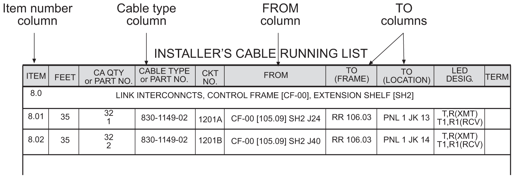
- Locate the Installer’s Cable Running List in the Equipment Specification for the site. Refer to Figure C-1 for an example.
Figure C-1 Installer’s Cable Running List Example
Cables and Adapters
Cables and adapters are listed in alphabetical order.
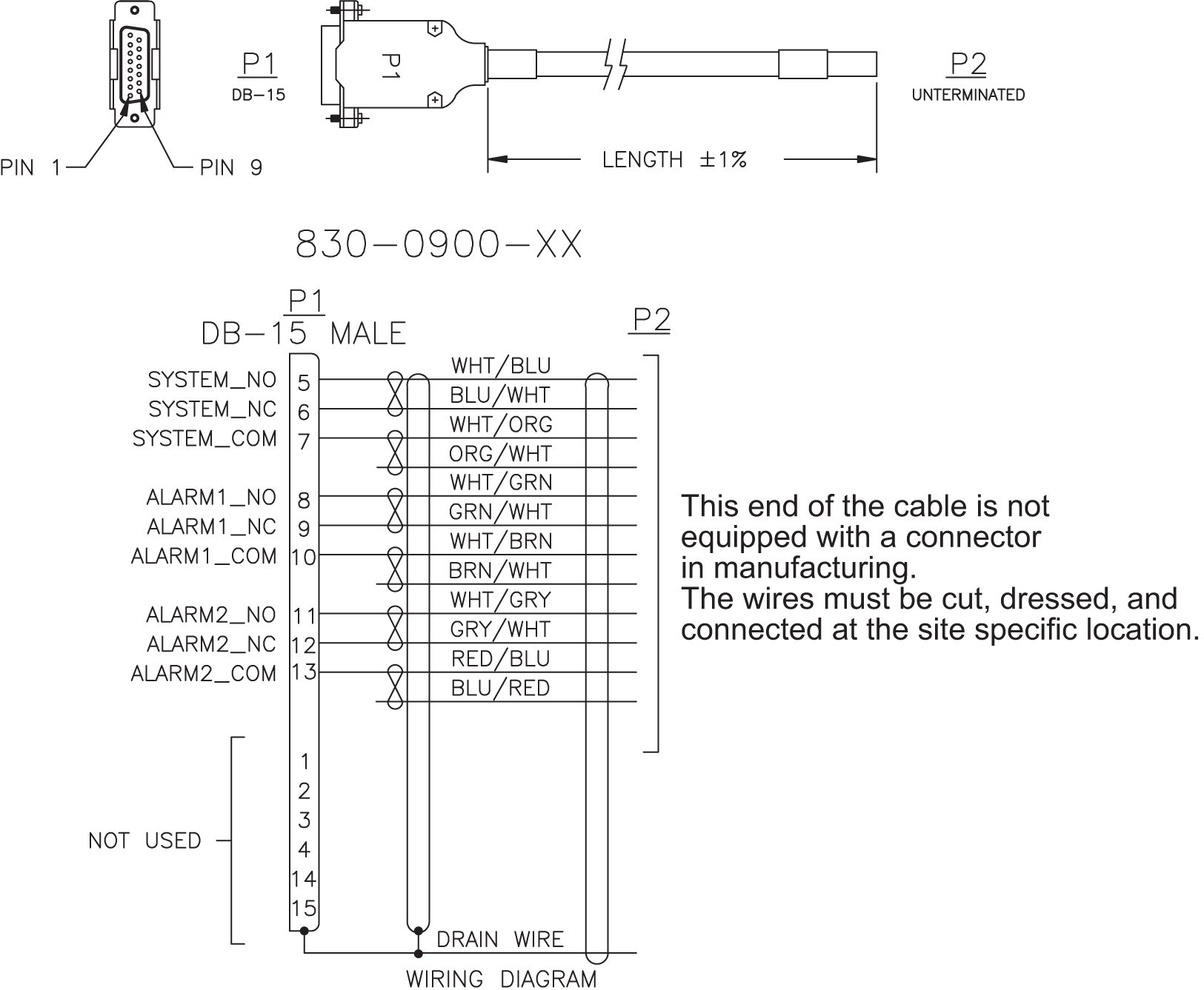
The words NOT TERMINATED or UNTERMINATED refers to the end of the cable that is not equipped with a connector in manufacturing and the wires must be cut, dressed, and connected at the site specific location.
Cable and Adapter Use
Table C-1 shows the cables and adapters used for E5-type cards in new installations in a vacant uncabled slot in a shelf.
Note:
References to E5- type cards include E5-B type cards.Note:
Exceptions, additions, and clarifications to the following tables are by superscript numeric notation relating to the listed notes located at the end of this section. The notations are indicated as a numbered step reference (such as 1) which corresponds to the appropriate note which is shown at the end of this section. For example, a table cell with X1,2 would indicate that notes 1 and 2 are applicable to that component.Table C-1 Cable/Adapter Use - New Installation
| Card P/N | Application | Adapter | Qty | Cable | Qty |
|---|---|---|---|---|---|
|
E5-E1T1-B 870-2970-xx |
E1 |
No adapters required |
830-1132-XX or non-ROHS 830-0011-XX 5 |
1 |
|
|
T1 |
No adapters required |
7112462 830-1197-XX or non-ROHS 830-0949-XX |
2 |
||
|
E5-ENET-B 870-2971-xx |
IPLIM IPGW IPSG STC |
830-1102-XX |
2 |
830-1174-XX or non-ROHS 870-0724-XX |
2 |
|
OR 830-1103-XX |
2 |
830-1204-XX or non-ROHS 830-0978-XX 2 |
2 |
||
|
FAST COPY |
830-1343-01 3 |
1 |
830-1204-XX or non-ROHS 830-0978-XX |
1 |
|
|
830-1174-XX or non-ROHS 870-0724-XX |
1 |
||||
|
AND 830-1343-02 4 |
1 |
830-1204-XX or non-ROHS 830-0978-XX |
1 |
||
|
830-1174-XX or non-ROHS 870-0724-XX |
1 |
||||
|
OR 830-1102-XX |
2 |
830-1174-XX or non-ROHS 870-0724-XX |
4 |
||
|
E5-SM8G-B 870-2990-01 |
SCCP (ExAP Interface) |
830-1104-XX |
2 |
830-1174-XX or non-ROHS 870-0724-XX |
2 |
|
GTT |
No adapters required | No cables required | |||
|
E5-ENET-B 870-2971-xx |
IPSM |
OR 830-1103-XX |
1 |
830-1204-XX or non-ROHS 830-0978-XX |
1 |
|
E5-ATM-B 870-2972-01 |
ATM-T1 |
No adapters required |
7112462 830-1197-XX or non-ROHS 830-0949-XX 5 |
1 |
|
|
ATM-E1 |
No adapters required |
830-1132-XX or non-ROHS 830-0011-XX 5 |
1 |
||
|
ATM-T1 |
830-1342-05 OR 830-1342-06 |
1 |
7112462 830-1197-XX or non-ROHS 830-0949-XX 6 |
2 |
|
|
ATM-E1 |
830-1342-05 OR 830-1342-06 |
1 |
830-1132-XX or non-ROHS 830-0011-XX 6 |
2 |
|
|
E5-MASP 7346924 870-2903-xx |
OAM |
830-1333-02 |
1 |
||
|
E5-MCPM-B |
MCP |
830-1102-XX |
1 |
830-1174-XX or non-ROHS 870-0724-XX |
1 |
|
SLIC 7094646 |
ENUM DEIR SIP SCCP (ExAP Interface) |
830-1102-03 |
2 |
830-1174-XX CAT6A 830-1404-xx |
2 |
|
IPSG |
830-1102-03 |
2 |
830-1174-XX CAT6A 830-1404-xx |
4 |
|
|
IPS MCP STC |
830-1102-03 |
1 |
830-1174-XX |
1 |
|
|
GTT |
No adapters required |
No cables required |
|||
|
SLIC 7094646 |
E1 |
No adapters required |
830-1132-XX or non-ROHS 830-0011-XX 5 |
1 |
|
|
T1 |
No adapters required |
7112462 830-1197-XX or non-ROHS 830-0949-XX |
2 |
Notes:
Alarm NETRA Server Cable (P/N 830-0900-xx)
Table C-2 Alarm NETRA Server Cable (P/N 830-0900-xx)
| Part Number | Length |
|---|---|
| 830-0900-01 | 50.0 FT |
| 830-0900-02 | 75.0 FT |
| 830-0900-03 | 100.0 FT |
| 830-0900-04 | 125.0 FT |
| 830-0900-05 | 150.0 FT |
| 830-0900-06 | 175.0 FT |
| 830-0900-07 | 200.0 FT |
Figure C-3 Alarm NETRA Server Cable
B-Clock Cable
Table C-3 Clock Cable
| Part Number | Length (inches) | Part Number | Length (inches) | ||
|---|---|---|---|---|---|
| North American | International | North American | International | ||
|
830-0398-01 |
830-1150-01 |
96 |
830-0398-12 |
-- |
164 |
|
830-0398-02 |
-- |
144 |
830-0398-13 |
830-1150-13 |
176 |
|
830-0398-03 |
-- |
192 |
830-0398-14 |
830-1150-14 |
208 |
|
830-0398-04 |
830-1150-04 |
240 |
830-0398-15 |
-- |
224 |
|
830-0398-05 |
-- |
288 |
830-0398-16 |
-- |
232 |
|
830-0398-06 |
830-1150-06 |
360 |
830-0398-17 |
830-1150-17 |
252 |
|
830-0398-07 |
-- |
18 |
830-0398-18 |
-- |
272 |
|
830-0398-08 |
-- |
48 |
830-0398-19 |
830-1150-19 |
284 |
|
830-0398-09 |
-- |
84 |
830-0398-20 |
830-1150-20 |
52 |
|
830-0398-10 |
830-1150-10 |
116 |
830-0398-21 |
830-1150-21 |
78 |
|
830-0398-11 |
830-1150-11 |
132 |
|||
Figure C-4 Clock Cable
BNC- to-BNC Cable Assembly (P/N 830-0624-xx)
Table C-4 BNC to BCN Cable Assembly (P/N 830-0624-xx)
| Part Number | Length (FT) |
|---|---|
| 830-0624-01 | 15.0 |
| 830-0624-02 | 25.0 |
| 830-0624-03 | 50.0 |
| 830-0624-04 | 75.0 |
| 830-0624-05 | 100.0 |
| 830-0624-06 | 125.0 |
| 830-0624-07 | 150.0 |
| 830-0624-08 | 175.0 |
| 830-0624-09 | 200.0 |
| 830-0624-10 | 250.0 |
| 830-0624-11 | 300.0 |
| 830-0624-12 | 500.0 |
| 830-0624-13 | 1000.0 |
Figure C-5 BNC to BCN Cable Assembly (P/N 830-0624-xx)

BNC/Open End Cable
Table C-5 BNC/Open End Cable
| Part Number | Length | ||
|---|---|---|---|
| North American | International | feet | meters |
|
830-0625-01 |
830-1161-01 |
15 |
4.57 |
|
830-0625-02 |
830-1161-02 |
25 |
7.62 |
|
830-0625-03 |
830-1161-03 |
50 |
15.24 |
|
830-0625-04 |
830-1161-04 |
75 |
22.86 |
|
830-0625-05 |
830-1161-05 |
100 |
30.48 |
|
830-0625-06 |
830-1161-06 |
125 |
38.10 |
|
830-0625-07 |
830-1161-07 |
150 |
45.72 |
|
830-0625-08 |
830-1161-08 |
175 |
53.34 |
|
830-0625-09 |
830-1161-09 |
200 |
60.96 |
|
830-0625-10 |
830-1161-10 |
250 |
76.2 |
|
830-0625-11 |
830-1161-11 |
300 |
91.44 |
|
830-0625-12 |
830-1161-12 |
500 |
152.4 |
|
830-0625-13 |
830-1161-13 |
1000 |
304.8 |
Figure C-6 BNC/Open End Cable

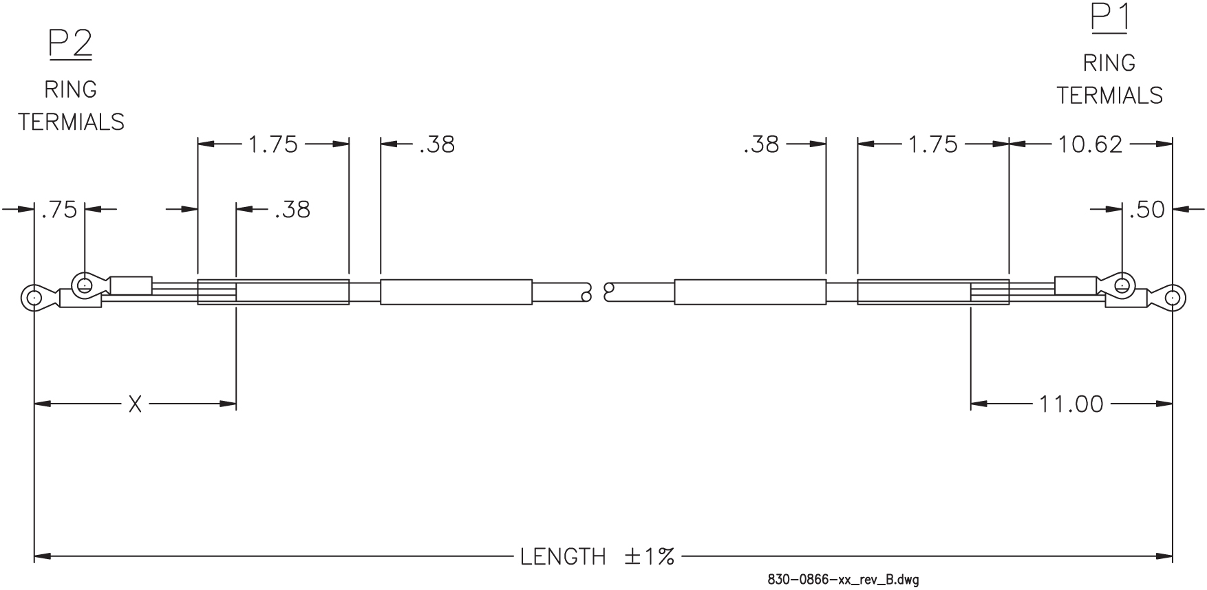
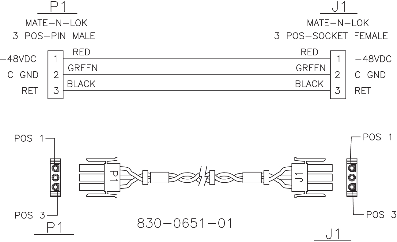
Breaker-to-Terminal Strip Power Cable
Table C-6 Power Cable to Breaker Strip
| Part Number | Length | P1 Long Lead | P2 Long Lead | Label “A” usage | Label “B” usage | ||
|---|---|---|---|---|---|---|---|
| North American | International | Inches | Meters | ||||
|
830-0866-01 |
830-1236-01 |
48.5 |
14.78 |
Black |
Red |
BP-1, POS 1B |
TB1, POS 3 and 4 |
|
830-0866-02 |
830-1236-02 |
51.5 |
15.69 |
Black |
Black |
BP-2, POS 1B |
TB2, POS 3 and 4 |
|
830-0866-03 |
830-1236-03 |
53.5 |
16.30 |
Black |
Red |
BP-1, POS 1A |
TB3, POS 3 and 4 |
|
830-0866-04 |
830-1236-04 |
46.5 |
14.17 |
Black |
Black |
BP-2, POS 1B |
TB4, POS 3 and 4 |
|
830-0866-05 |
--- |
86.0 |
26.21 |
Black |
Red |
BP-2, POS 3B |
TB2, POS 3 and 4 |
|
830-0866-06 |
--- |
88.0 |
88.0 |
Black |
Black |
BP-1, POS 3A |
TB3, POS 3 and 4 |
Figure C-7 Power Cable to Breaker Strip
Converter
This straight through converter is a purchased part. There is no illustration or wiring diagram.
Crossover (CAT-5) Cable
Table C-7 Crossover CAT-5 Cable
| Part Number | Length | ||
|---|---|---|---|
| North American | International | meters | feet |
|
830-0723-01 |
830-1173-01 |
0.30 |
1 |
|
830-0723-02 |
830-1173-02 |
0.90 |
3 |
|
830-0723-03 |
830-1173-03 |
1.37 |
4.5 |
|
830-0723-xx |
830-1173-xx |
available in many more lenghts |
|
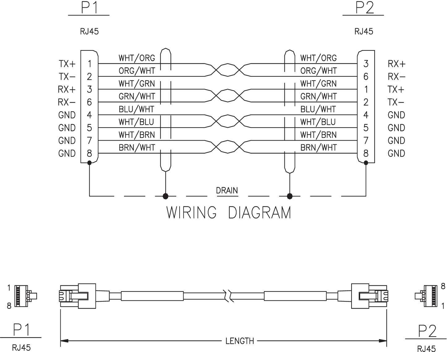
Figure C-9 Crossover CAT-5 Cable
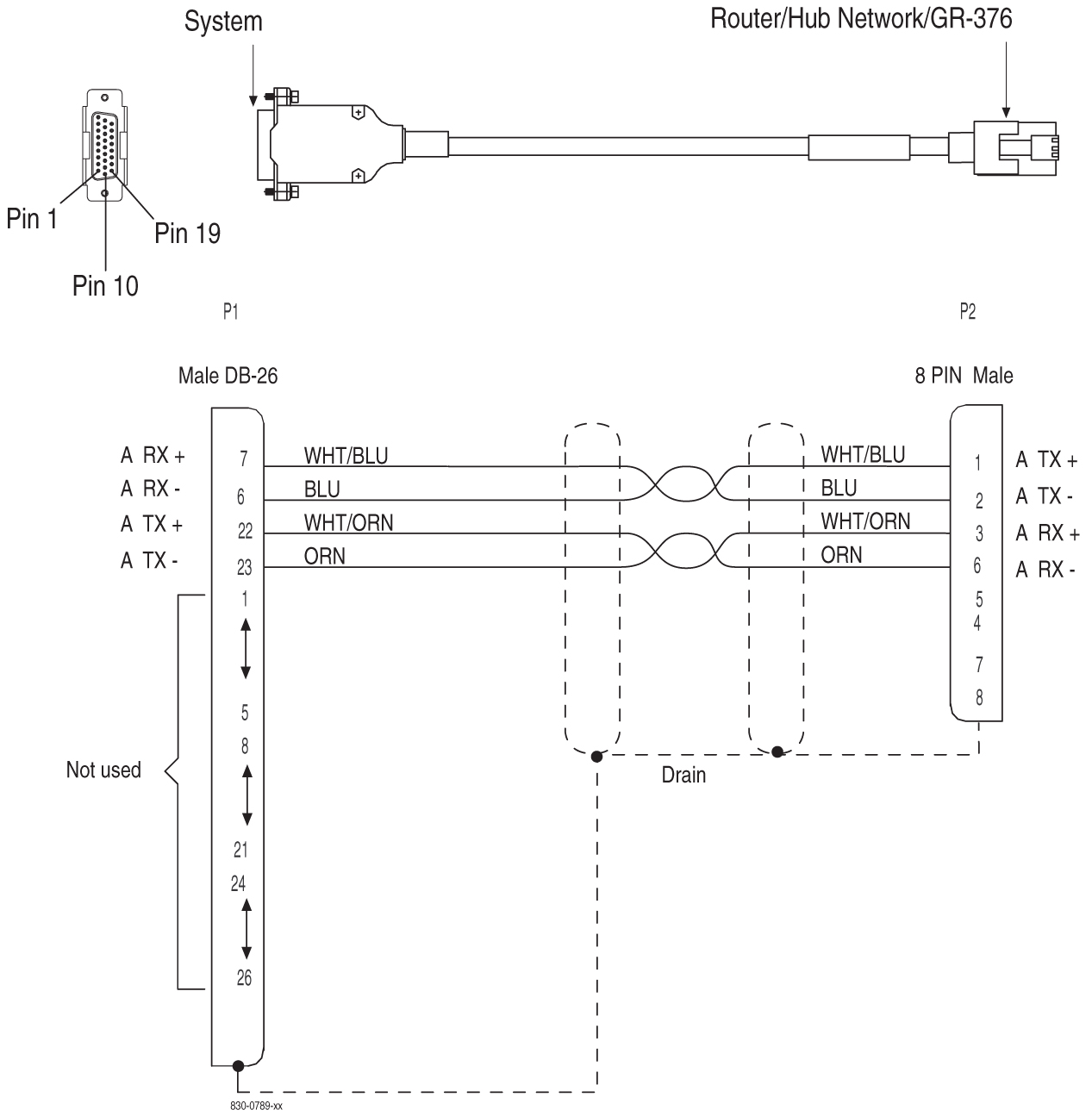
Crossover DCM Patch Panel Cable
Table C-8 Crossover DCM Patch Panel Cable
| Part Number | Length | ||
|---|---|---|---|
| North American | International | feet | meters |
|
830-0789-01 |
830-1178-01 |
15 |
4.57 |
|
830-0789-02 |
830-1178-02 |
25 |
7.62 |
|
830-0789-03 |
830-1178-03 |
35 |
10.67 |
|
830-0789-04 |
830-1178-04 |
50 |
15.25 |
|
830-0789-05 |
830-1178-05 |
75 |
45.75 |
|
830-0789-06 |
830-1178-06 |
100 |
30.50 |
|
830-0789-07 |
830-1178-07 |
150 |
45.75 |
|
830-0789-08 |
830-1178-08 |
200 |
60.10 |
|
830-0789-09 |
830-1178-09 |
250 |
76.25 |
|
830-0789-10 |
830-1178-10 |
328 |
107.54 |
Figure C-10 Crossover DCM Patch Panel Cable
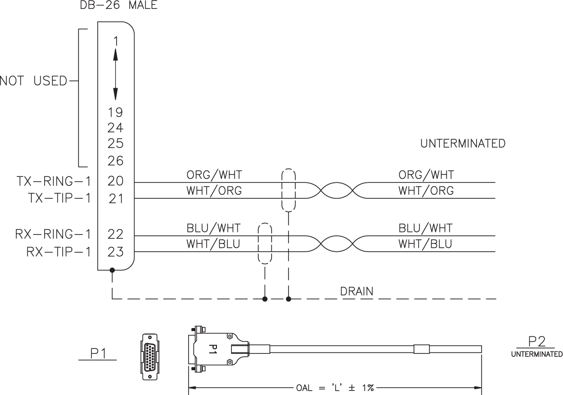
DS1 Cable
Table C-9 DS1 Cable
| Part Number | Length | ||
|---|---|---|---|
| North American | International | feet | meters |
|
830-0849-01 |
830-1184-01 |
15 |
4.57 |
|
830-0849-02 |
830-1184-02 |
20 |
6.09 |
|
830-0849-03 |
830-1184-03 |
25 |
7.62 |
|
830-0849-04 |
830-1184-04 |
30 |
9.14 |
|
830-0849-05 |
830-1184-05 |
35 |
10.66 |
|
830-0849-06 |
830-1184-06 |
50 |
15.24 |
|
830-0849-07 |
830-1184-07 |
75 |
22.86 |
|
830-0849-08 |
830-1184-08 |
100 |
30.48 |
|
830-0849-09 |
830-1184-09 |
125 |
38.10 |
|
830-0849-10 |
830-1184-10 |
150 |
45.72 |
|
830-0849-11 |
830-1184-11 |
175 |
53.34 |
|
830-0849-12 |
830-1184-12 |
200 |
60.96 |
|
830-0849-13 |
830-1184-13 |
250 |
76.20 |
|
830-0849-14 |
830-1184-14 |
300 |
91.44 |
|
830-0849-15 |
830-1184-15 |
500 |
152.40 |
|
830-0849-16 |
830-1184-16 |
650 |
198.12 |
Figure C-13 DS1 Cable DS1 Cable
E1 Cable
Table C-10 E1 Cable
| Part Number | Length | Part Number | Length | ||||
|---|---|---|---|---|---|---|---|
| North American | International | feet | meters | North American | International | feet | meters |
|
830-0622-01 |
830-1233-01 |
15 |
4.57 |
830-0622-08 |
830-1233-08 |
175 |
53.34 |
|
830-0622-02 |
830-1233-02 |
25 |
7.62 |
830-0622-10 |
830-1233-09 |
200 |
60.96 |
|
830-0622-03 |
830-1233-03 |
50 |
15.24 |
830-0622-11 |
830-1233-10 |
250 |
76.20 |
|
830-0622-04 |
830-1233-04 |
75 |
22.86 |
830-0622-12 |
830-1233-11 |
300 |
91.44 |
|
830-0622-05 |
830-1233-05 |
100 |
30.48 |
830-0622-13 |
830-1233-12 |
500 |
152.40 |
|
830-0622-06 |
830-1233-06 |
125 |
38.10 |
830-0622-14 |
830-1233-13 |
1000 |
304.8 |
|
830-0622-07 |
830-1233-07 |
150 |
45.72 |
830-0622-15 |
830-1233-15 |
400 |
121.92 |
Figure C-14 E 1 Cable
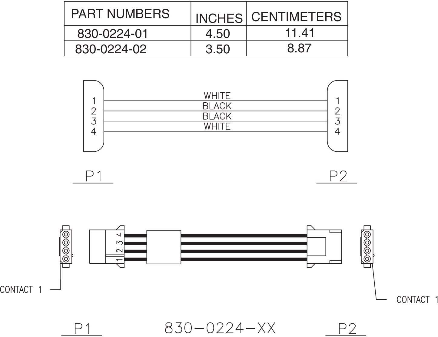
E1 Patch Cable
Table C-11 E1 Patch Cable
| Part Number | Length | ||
|---|---|---|---|
| North American | International | Inches | Centimeters |
|
830-0605-01 |
-- |
12 |
30.48 |
|
830-0605-02 |
830-1116-02 |
15 |
38.1 |
Figure C-15 E1 Patch Cable
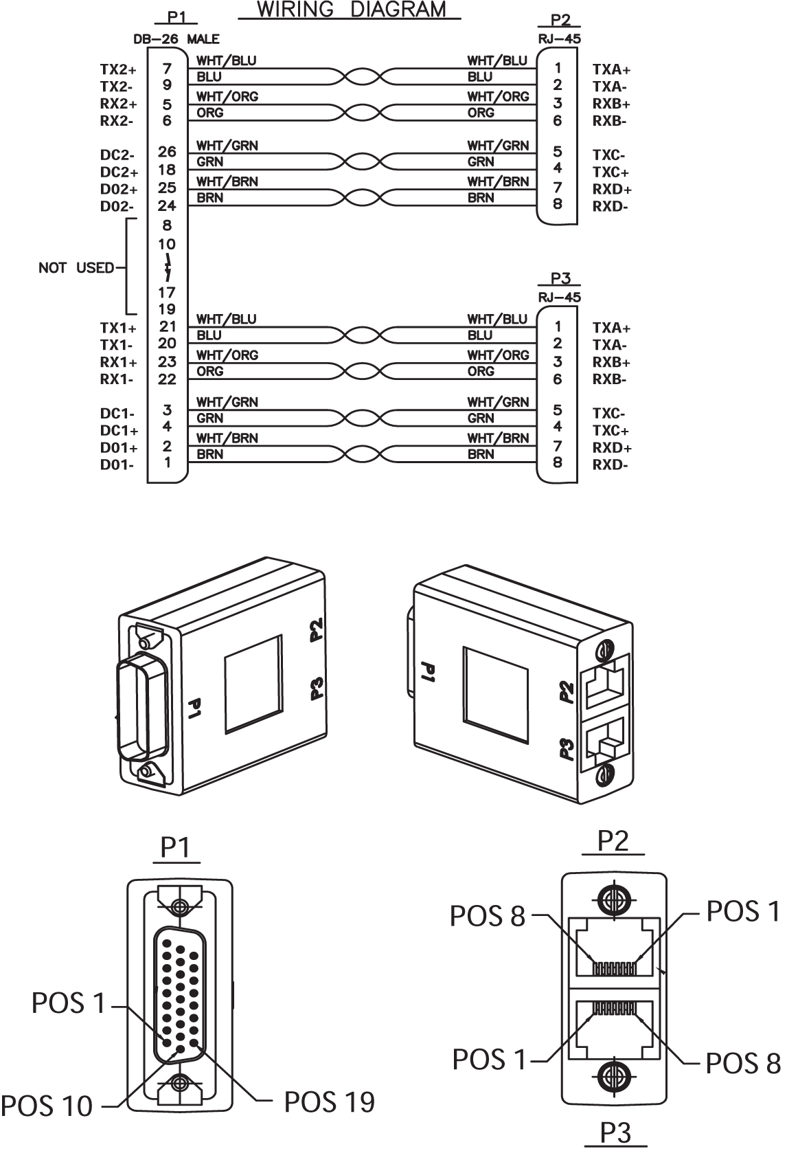
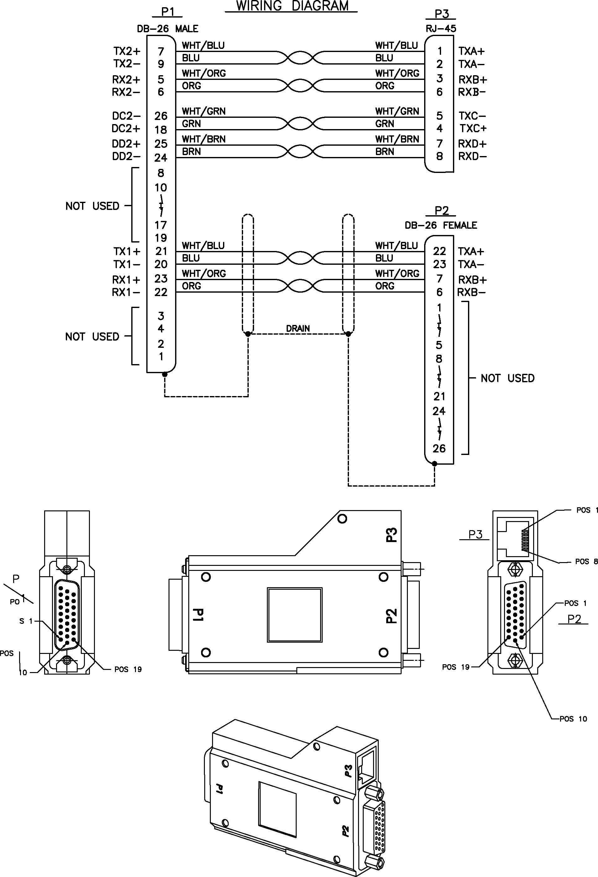
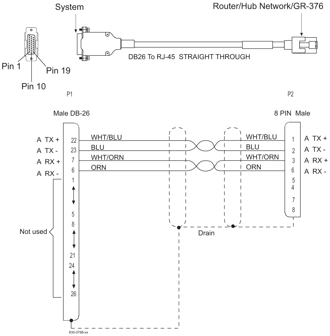
E5-ENET ADAPTER (DB26 Male-to-Dual RJ45)
The Ethernet cable pinouts differ between the E5-ENET card and the DCM or single-slot EDCM cards.
Adapter 830-1102-02 is required for installation of the E5-ENETwhen the DCM cable is replaced with a CAT5 straight-through cable 830-0724-xx. The adapter is connected to the backplane and the CAT5 straight-through cable cable is connected from the other side of the adapter to a switch, or a hub, or a patch panel (same place the DCM cable was terminated). If the card inserted into the slot does not match the backplane connector, the interface will not function.
Figure C-17 DB26 Male to Dual RJ45 Adapter
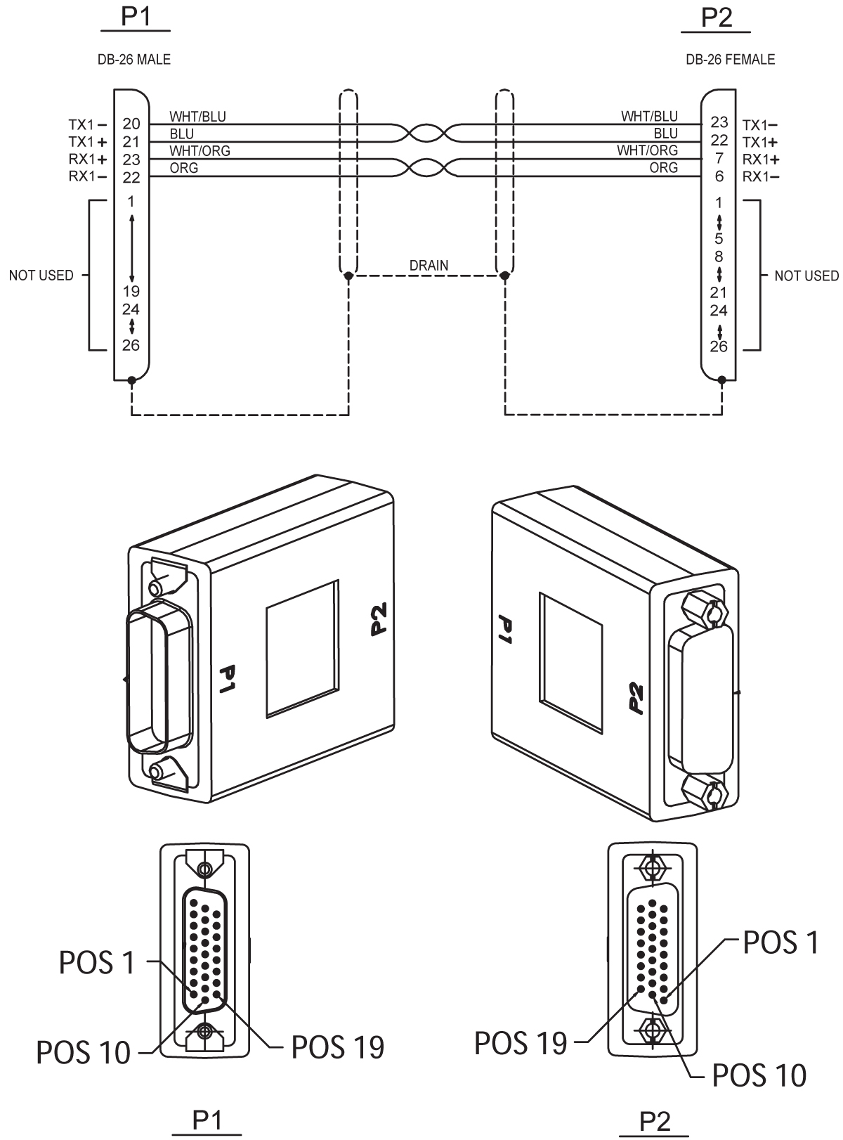
E5-ENET ADAPTER (DB26 Male-to-DB26 Female)
The Ethernet cable pinouts differ between the E5-ENET card and the DCM or single-slot EDCM cards.
Adapter 830-1103-02 is required for each E5-ENET interface used when using the existing DCM cable 830-0978-xx. The adapter is connected between the backplane connector and the existing DCM cable for the card.
Figure C-18 DB26 Male-to-DB26 Female Adapter
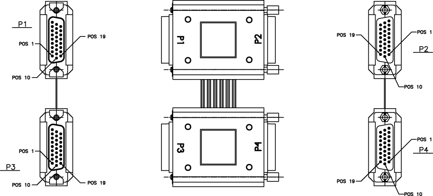
E5-ENET FAST COPY ADAPTER, LOWER
The Ethernet cable pinouts differ between the E5-ENET card and the DCM or single-slot EDCM cards.
Adapter P/N 830-1343-02 is required for each E5-ENET interface used when using the FAST COPY feature. The adapter is connected between the backplane connector and the existing DCM cable for the card.
Figure C-19 E5-ENET FAST COPY ADAPTER, LOWER, P/N 830-1343-02
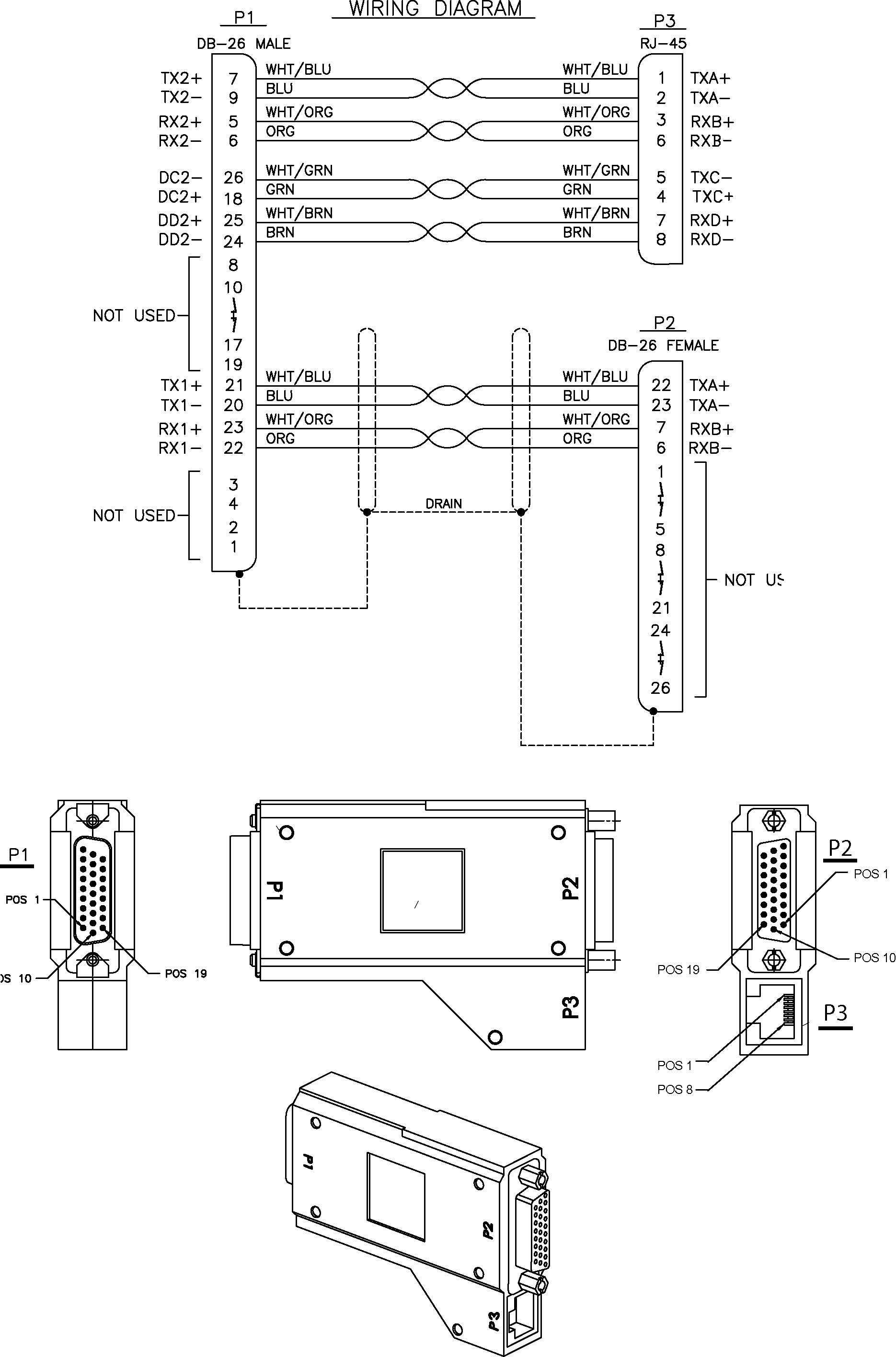
E5-ENET FAST COPY ADAPTER, UPPER
The Ethernet cable pinouts differ between the E5-ENET card and the DCM or single-slot EDCM cards.
Adapter P/N 830-1343-01 is required for each E5-ENET interface used when using the FAST COPY feature. The adapter is connected between the backplane connector and the existing DCM cable for the card.
Figure C-20 E5-ENET FAST COPY ADAPTER, UPPER, P/N 830-1343-01
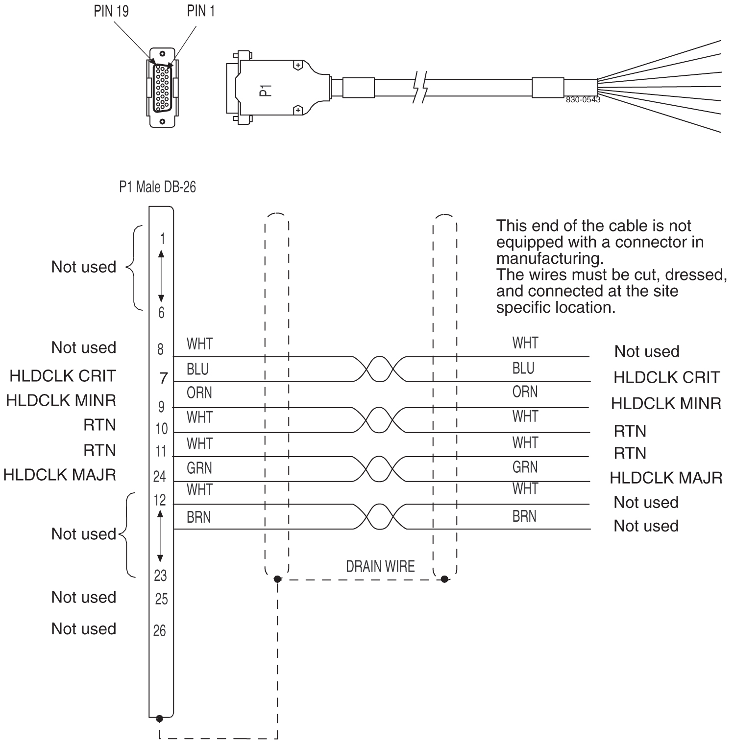
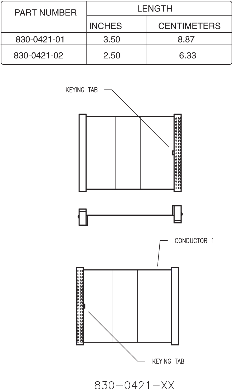
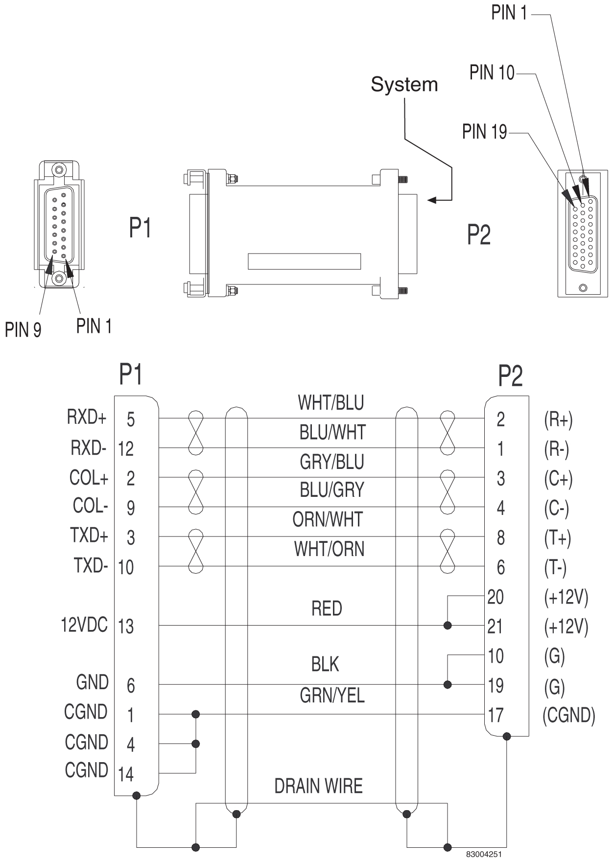
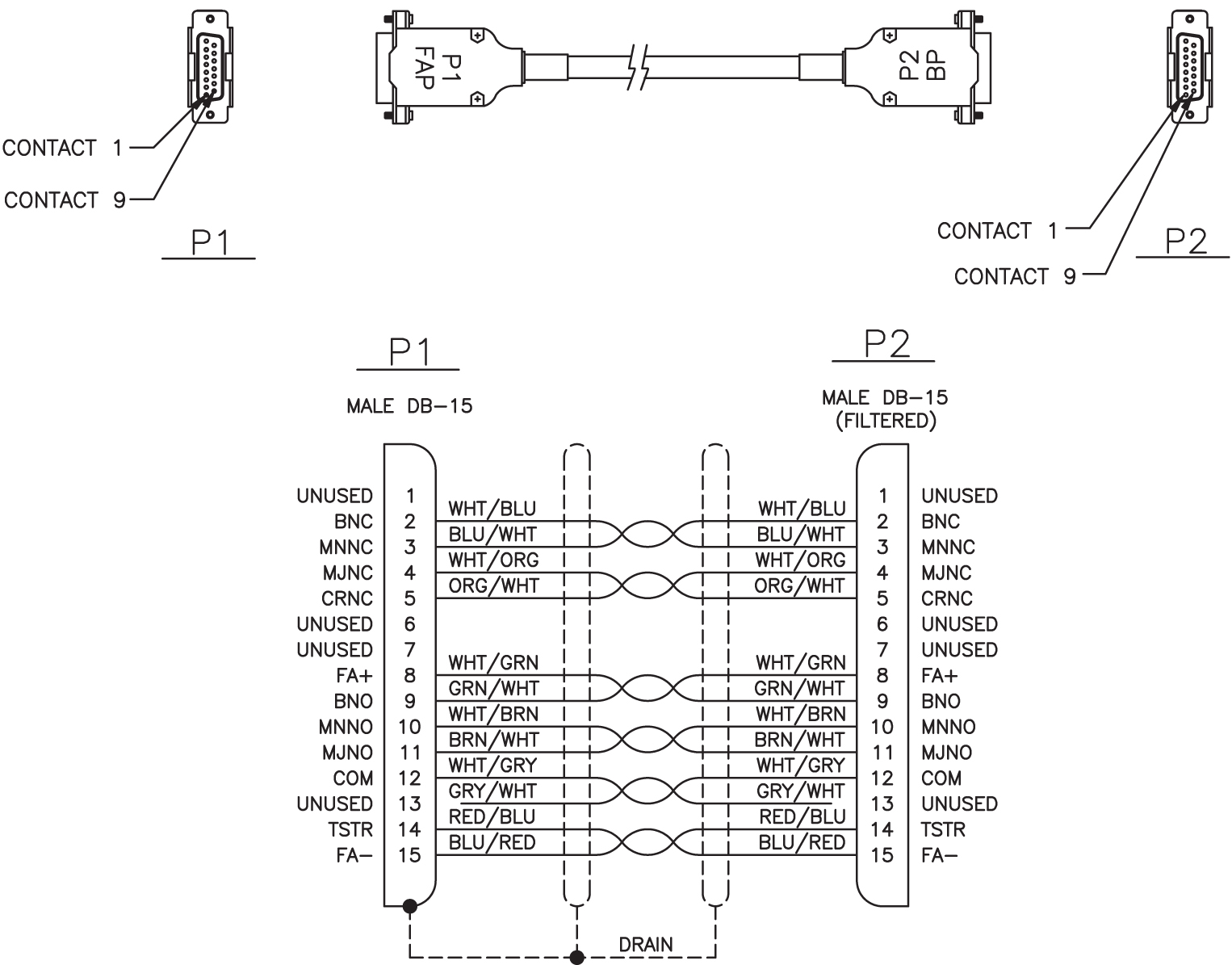
ENET Adapter 15-Pin to 26-Pin (P/N 830-0425-01)
Figure C-21 ENET Adapter 15-Pin to 26-Pin (P/N 830-0425-01)
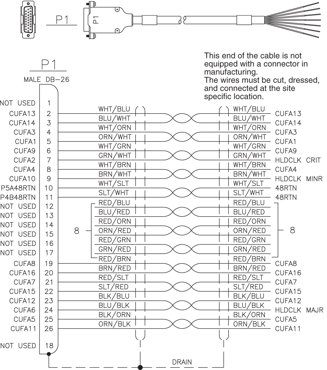
External Alarm Cable (Custom)
Table C-12 External Alarm Cable (Custom)
| Part Number | Length | ||
|---|---|---|---|
| North American | International | feet | meters |
|
830-0435-01 |
830-1151-01 |
50 |
15.24 |
|
830-0435-02 |
830-1151-02 |
75 |
22.86 |
|
830-0435-03 |
830-1151-03 |
100 |
30.48 |
|
830-0435-04 |
830-1151-04 |
125 |
38.10 |
|
830-0435-05 |
830-1151-05 |
150 |
45.72 |
|
830-0435-06 |
830-1151-06 |
175 |
53.34 |
|
830-0435-07 |
830-1151-07 |
200 |
61.96 |
|
830-0435-08 |
830-1151-08 |
250 |
76.20 |
|
830-0435-09 |
830-1151-09 |
300 |
91.40 |
|
830-0435-10 |
830-1151-10 |
500 |
152.40 |
|
830-0435-11 |
830-1151-11 |
1000 |
304.80 |
Figure C-22 External Alarm Cable (Custom)
Fan Power and Alarm Cable
The fan power and alarm cable is part of the fan assembly.
For A fan power, plug one end of the cable into J-9 on backplane 850-0330-06. Route the cable to the left of the frame, faced from the rear, and to the assembly, to the connection marked FAN A POWER.
For B fan power, plug one end of the cable into J-8 on the backplane 850-0330-06. Route the cable to the left of the frame, faced from the rear, and to the fan assembly, to the connection marked FAN B POWER. Form and dress the two cables together and check the security of all of the connections.
Filter Rack Alarm Cable
Table C-13 Filter Rack Alarm Cable
| Part Number | Length | ||
|---|---|---|---|
| North American | International | feet | meters |
|
830-0638-01 |
830-1163-01 |
5.0 |
1.524 |
|
830-0638-02 |
830-1163-02 |
8.0 |
2.438 |
|
830-0638-03 |
830-1163-03 |
11.0 |
3.352 |
|
830-0638-04 |
830-1163-04 |
14.0 |
4.267 |
|
830-0638-05 |
830-1163-05 |
17.0 |
5.182 |
|
830-0638-06 |
830-1163-06 |
20.0 |
6.069 |
|
830-0638-07 |
830-1163-07 |
21.5 |
6.553 |
|
830-0638-08 |
830-1163-08 |
27.5 |
8.382 |
Figure C-24 Filter Rack Alarm Cable
Hazard Ground Cable
Table C-14 Hazard Ground Cable
| Part Number | Length | Part Number | Length | ||
|---|---|---|---|---|---|
| inches | centimeters | inches | centimeters | ||
|
830-0257-01 |
15 |
38.1 |
830-0257-03 |
36 |
91.4 |
|
830-0257-02 |
24.75 |
62.9 |
830-0257-04 |
36 |
91.4 |
Figure C-26 Hazard Ground Cable

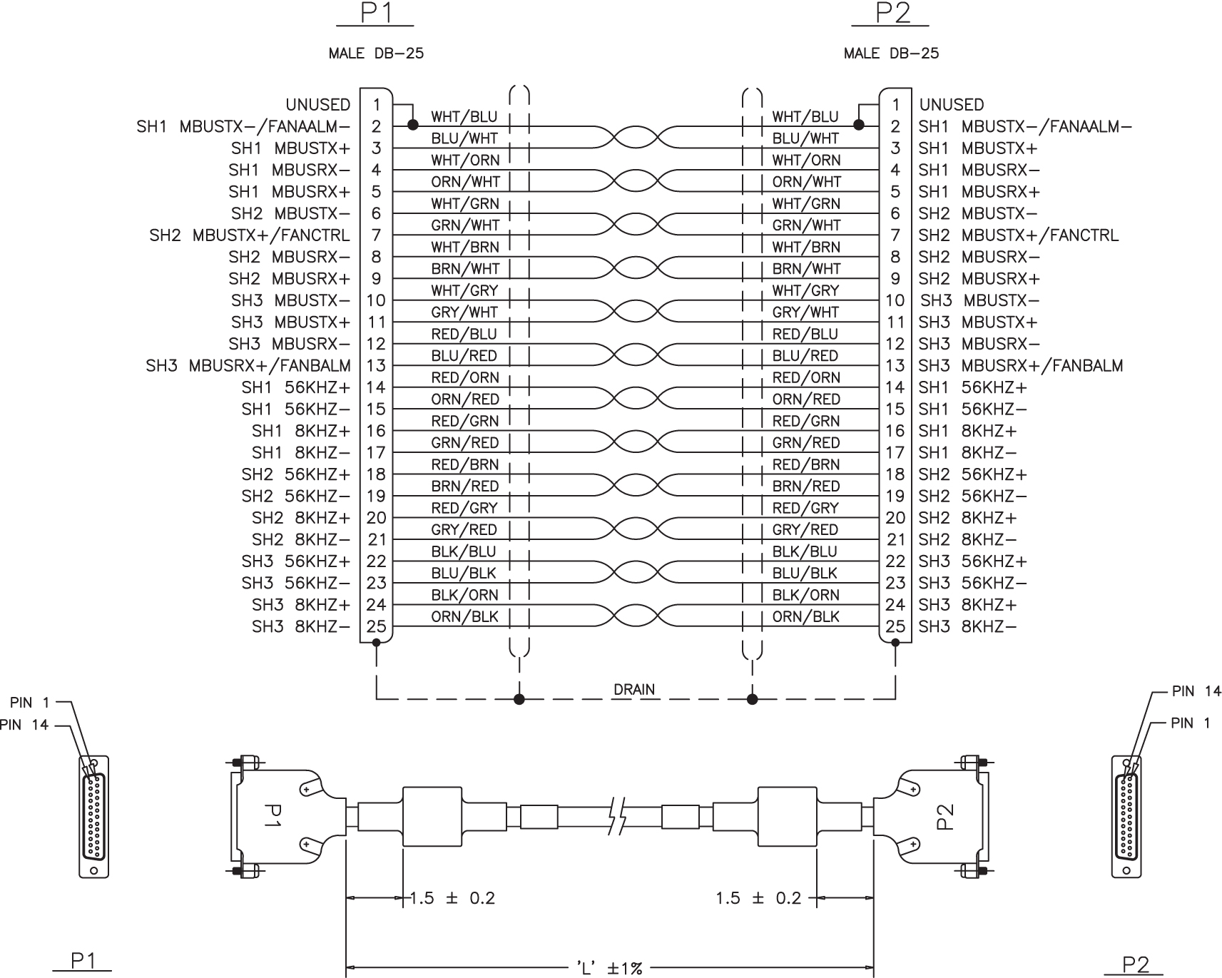
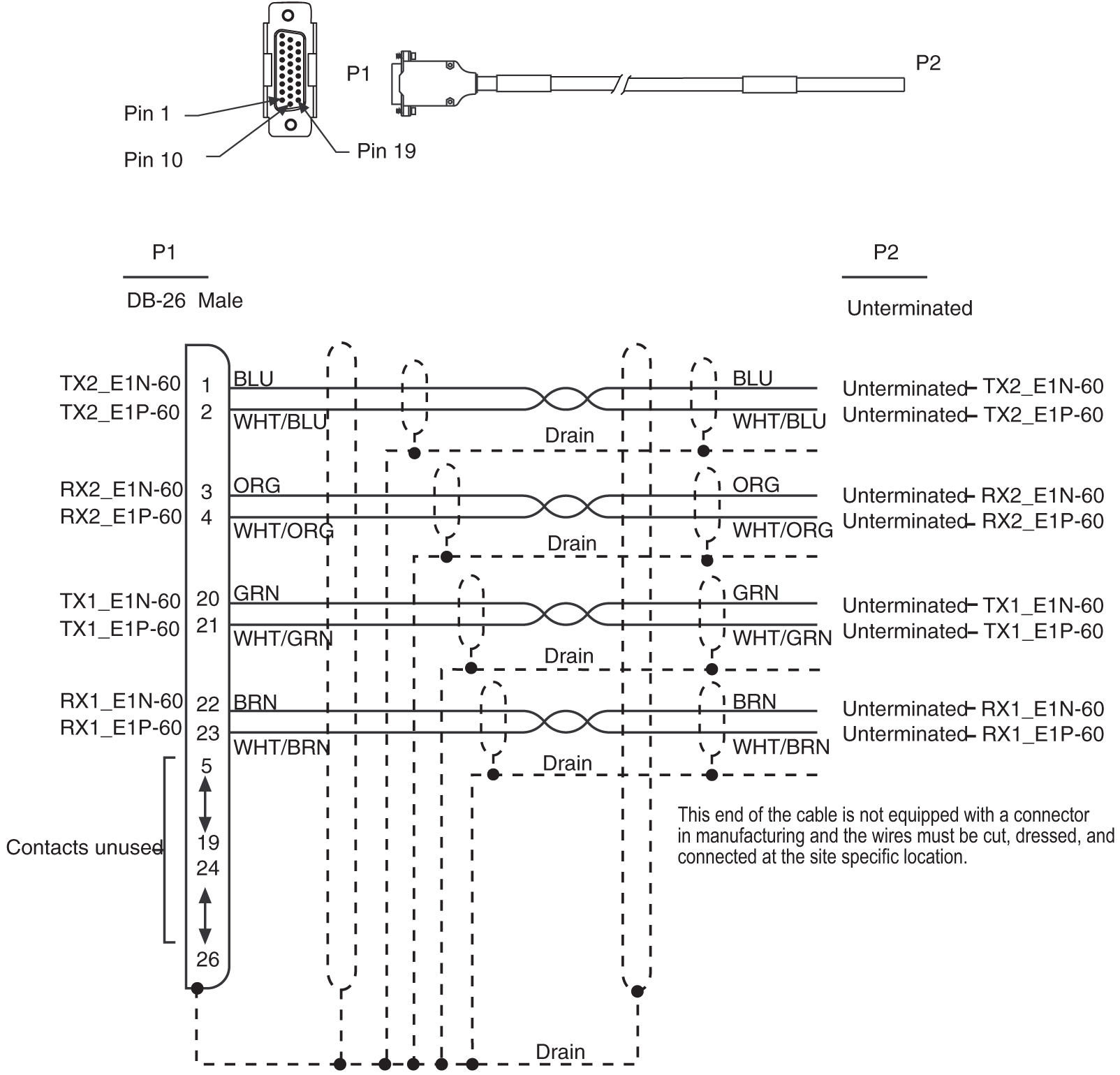
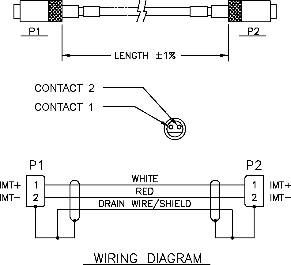
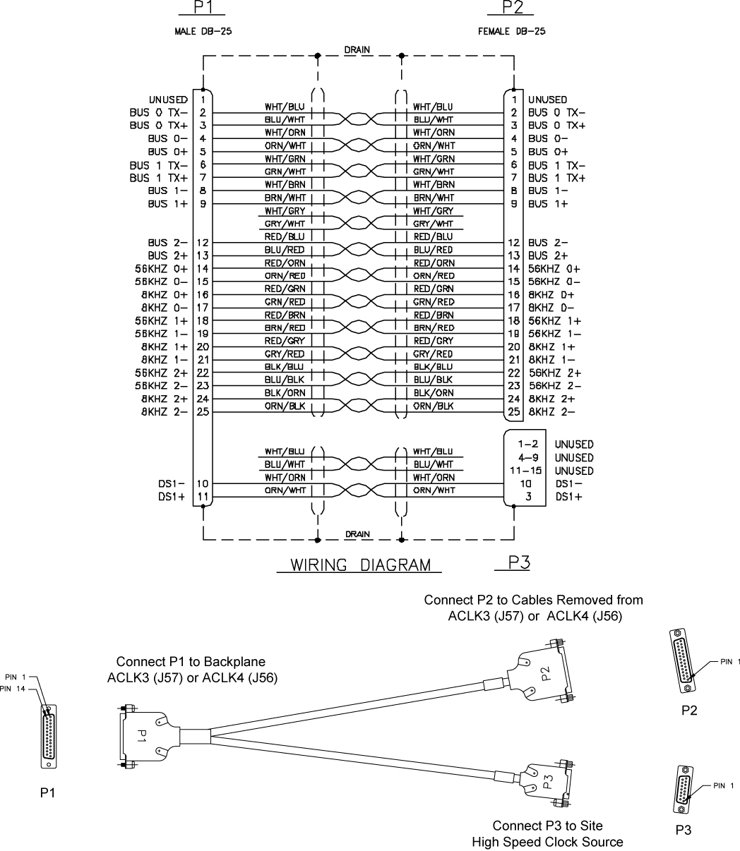
IMT Cable High Speed
Table C-15 Interface Cable High Speed
| Part Number | Length | |
|---|---|---|
| International | feet | meters |
|
830-1344-01 |
5.75 |
1.75 |
|
830-1344-02 |
7.67 |
2.34 |
|
830-1344-04 |
0.5 |
0.15 |
|
830-1344-05 |
14.0 |
4.27 |
|
830-1344-06 |
12.0 |
3.66 |
|
830-1344-07 |
13.0 |
3.96 |
|
830-1344-08 |
16.0 |
4.88 |
|
830-1344-09 |
19.0 |
5.79 |
|
830-1344-10 |
21.0 |
6.4 |
|
830-1344-11 |
23.0 |
7.01 |
|
830-1344-12 |
25.0 |
7.62 |
|
830-1344-15 |
11.0 |
3.35 |
|
830-1344-17 |
27.0 |
8.23 |
Figure C-28 IMT Cable
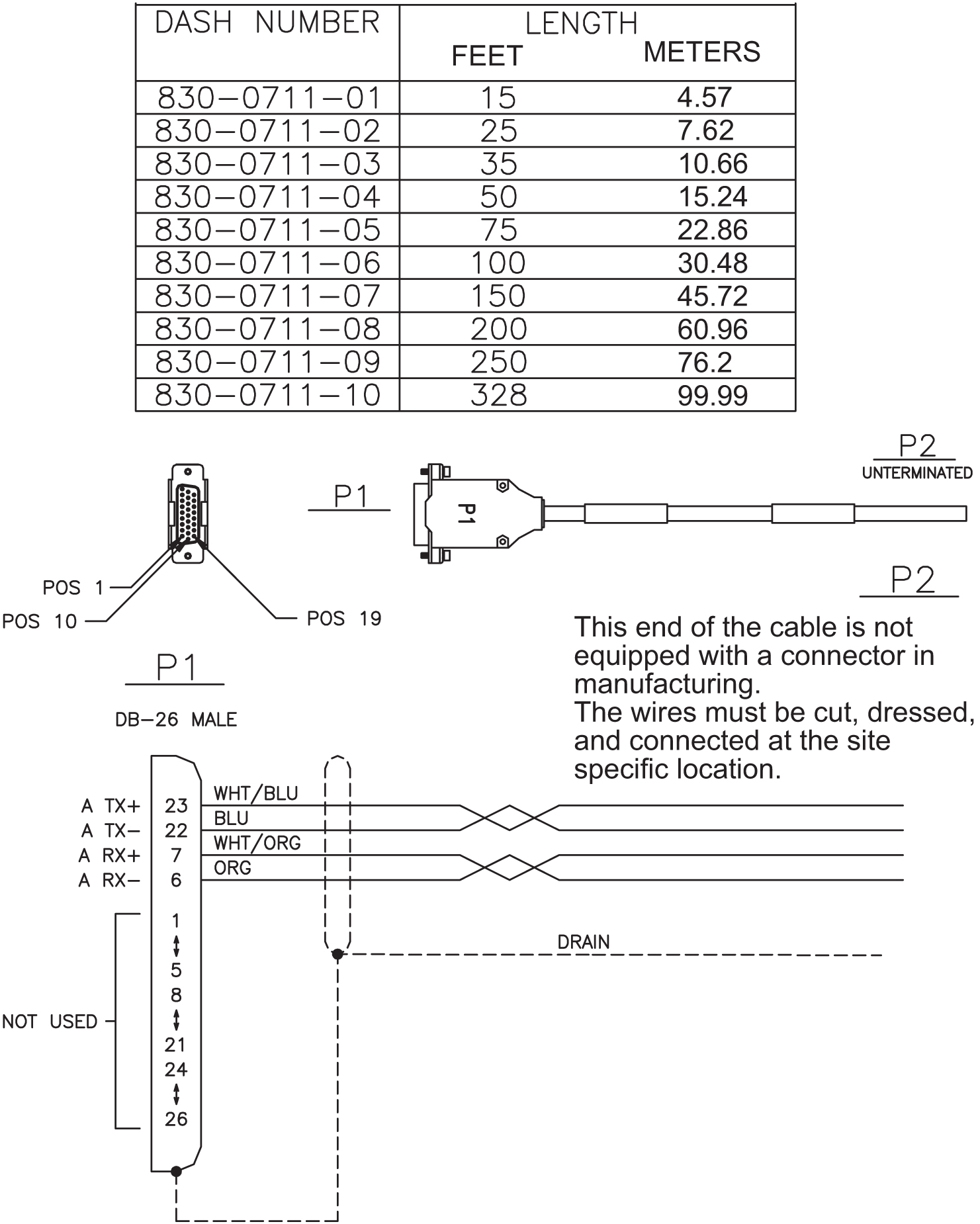
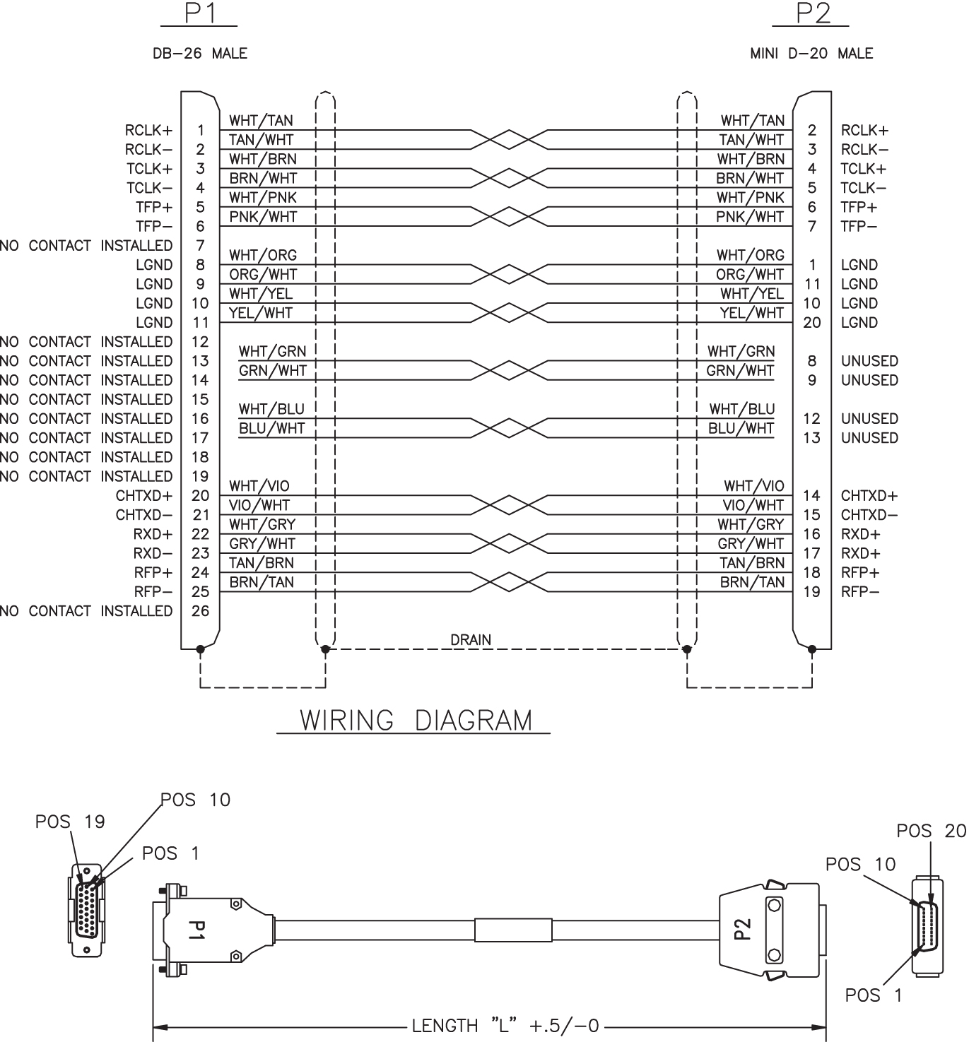
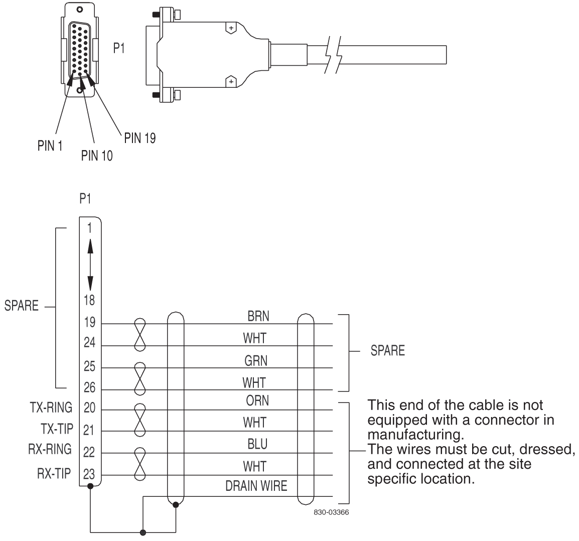
Interface Cable
Table C-16 Interface Cable
| Part Number | Length | ||
|---|---|---|---|
| North American | International | feet | meters |
|
830-0366-01 |
830-1149-01 |
25 |
7.63 |
|
830-0366-02 |
830-1149-02 |
35 |
10.68 |
|
830-0366-03 |
830-1149-03 |
50 |
15.25 |
|
830-0366-04 |
830-1149-04 |
75 |
22.88 |
|
830-0366-05 |
830-1149-05 |
100 |
30.50 |
|
830-0366-06 |
830-1149-06 |
125 |
38.13 |
|
830-0366-07 |
830-1149-07 |
150 |
45.75 |
|
830-0366-08 |
830-1149-08 |
175 |
53.38 |
|
830-0366-09 |
830-1149-09 |
200 |
61.00 |
|
830-0366-10 |
830-1149-10 |
250 |
76.25 |
|
830-0366-11 |
830-1149-11 |
300 |
91.50 |
|
830-0366-12 |
830-1149-12 |
500 |
152.50 |
|
830-0366-13 |
830-1149-13 |
1000 |
305.00 |
|
830-0366-14 |
830-1149-14 |
15 |
4.58 |
|
830-0366-15 |
830-1149-15 |
20 |
6.10 |
|
830-0366-16 |
830-1149-16 |
30 |
9.15 |
Figure C-29 Interface Cable
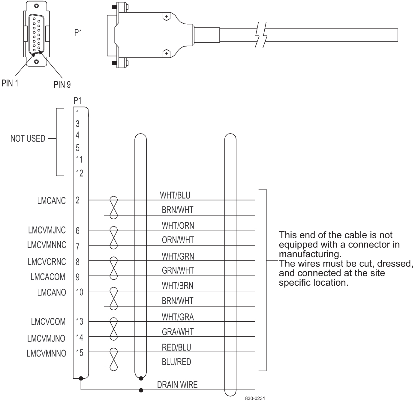
Local Maintenance Center Cable
Table C-17 Local Maintenance Center Cable
| Part Number | Length | ||
|---|---|---|---|
| North American | International | feet | meters |
|
830-0231-01 |
830-1144-01 |
50 |
15.25 |
|
830-0231-02 |
830-1144-02 |
75 |
22.88 |
|
830-0231-03 |
830-1144-03 |
100 |
30.50 |
|
830-0231-04 |
830-1144-04 |
125 |
38.13 |
|
830-0231-05 |
830-1144-05 |
150 |
45.75 |
|
830-0231-06 |
830-1144-06 |
175 |
53.38 |
|
830-0231-07 |
830-1144-07 |
200 |
61.00 |
|
830-0231-08 |
830-1144-08 |
250 |
76.25 |
|
830-0231-09 |
830-1144-09 |
300 |
91.50 |
|
830-0231-10 |
830-1144-10 |
500 |
152.50 |
|
830-0231-11 |
-- |
1000 |
305.00 |
Figure C-30 Local Maintenance Center Cable
MMI Port Cable
Table C-18 MMI Port Cable
| Part Number | Length | Part Number | Length | ||||
|---|---|---|---|---|---|---|---|
| North American | International | feet | meters | North American | International | feet | meters |
|
830-0708-01 |
830-1169-01 |
25 |
7.62 |
830-0708-14 |
830-1169-01 |
350 |
106.68 |
|
830-0708-02 |
830-1169-01 |
15 |
4.57 |
830-0708-15 |
830-1169-01 |
400 |
121.92 |
|
830-0708-03 |
830-1169-01 |
50 |
15.24 |
830-0708-16 |
830-1169-01 |
450 |
137.16 |
|
830-0708-04 |
830-1169-01 |
75 |
22.86 |
830-0708-17 |
830-1169-01 |
550 |
167.64 |
|
830-0708-05 |
830-1169-01 |
100 |
30.48 |
830-0708-18 |
830-1169-01 |
600 |
182.88 |
|
830-0708-06 |
830-1169-01 |
125 |
38.10 |
830-0708-19 |
830-1169-01 |
650 |
198.12 |
|
830-0708-07 |
830-1169-01 |
150 |
45.72 |
830-0708-20 |
830-1169-01 |
700 |
213.36 |
|
830-0708-08 |
830-1169-01 |
175 |
53.34 |
830-0708-21 |
830-1169-01 |
750 |
228.60 |
|
830-0708-09 |
830-1169-01 |
200 |
60.96 |
830-0708-22 |
830-1169-01 |
800 |
243.84 |
|
830-0708-10 |
830-1169-01 |
250 |
76.20 |
830-0708-23 |
830-1169-01 |
850 |
259.08 |
|
830-0708-11 |
830-1169-01 |
300 |
91.40 |
830-0708-24 |
830-1169-01 |
900 |
274.32 |
|
830-0708-12 |
830-1169-01 |
500 |
152.40 |
830-0708-25 |
830-1169-01 |
950 |
289.56 |
|
830-0708-13 |
830-1169-01 |
1000 |
304.80 |
||||
Figure C-34 Man-Machine Interface Port Cable
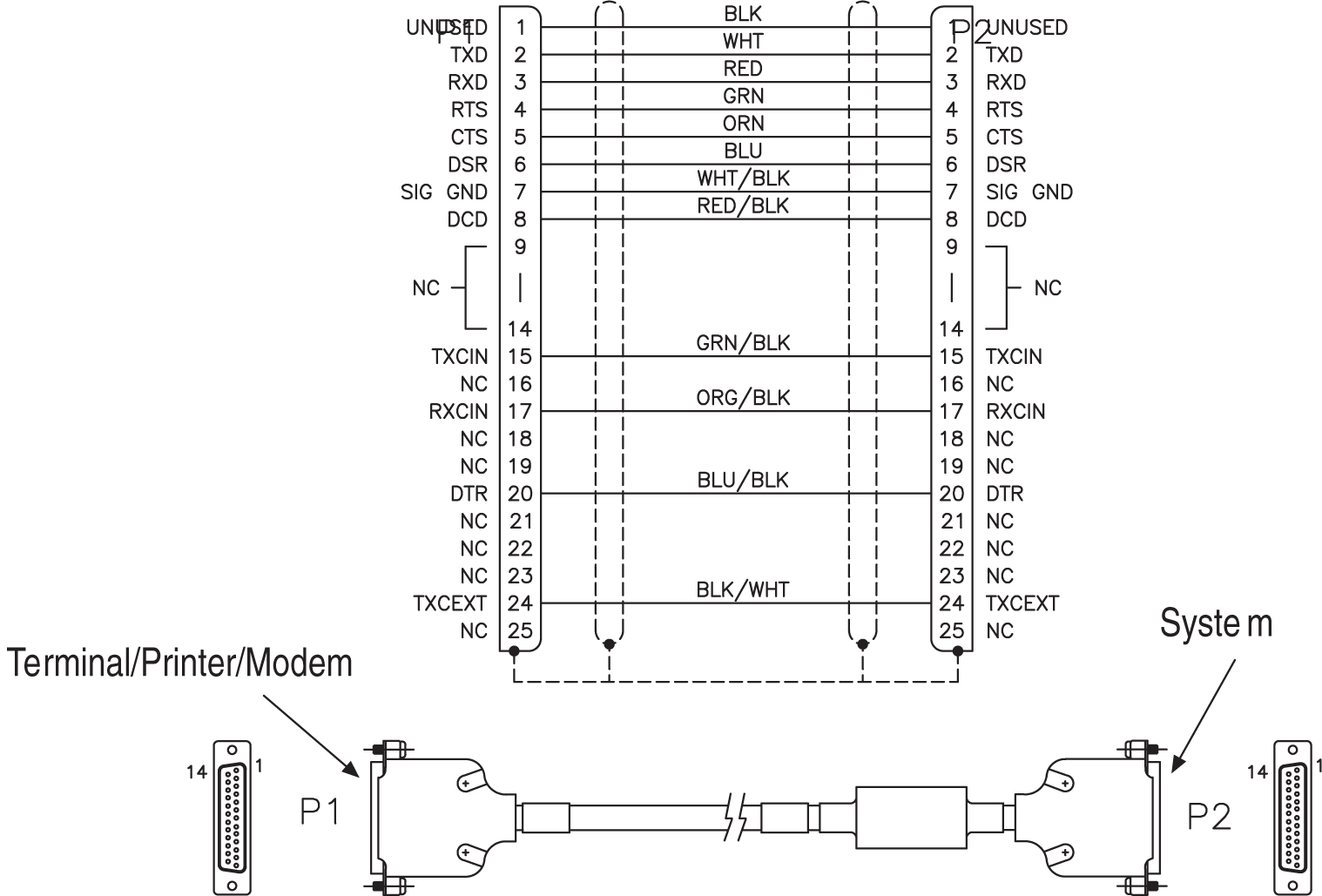
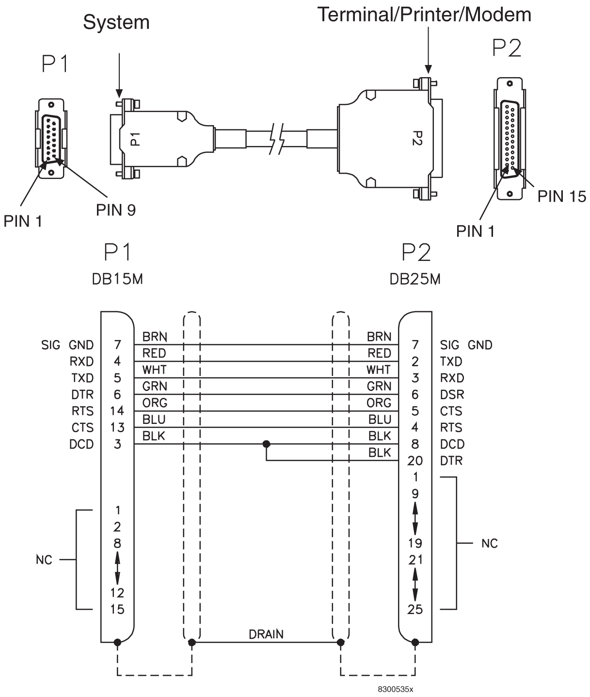
Modem/Terminal Cable
Table C-19 Modem/Terminal Cable
| Part Number | Length | ||
|---|---|---|---|
| North American | International | inches | centimeters |
|
830-0709-01 |
830-1170-01 |
180.0 +/- 1.8 |
457.2 |
|
830-0709-02 |
830-1170-02 |
300.0 +/- 3.0 |
762.0 |
|
830-0709-03 |
830-1170-03 |
600.0 +/- 6.0 |
1524.0 |
|
830-0709-04 |
830-1170-04 |
900.0 +/- 9.0 |
2286.0 |
|
830-0709-05 |
830-1170-05 |
1200.0 +/- 12.0 |
3048.0 |
|
830-0709-06 |
830-1170-06 |
1500.0 +/- 15.0 |
3810.0 |
|
830-0709-07 |
830-1170-07 |
1800.0 +/- 18.0 |
4572.0 |
Figure C-35 Modem/Terminal Cable
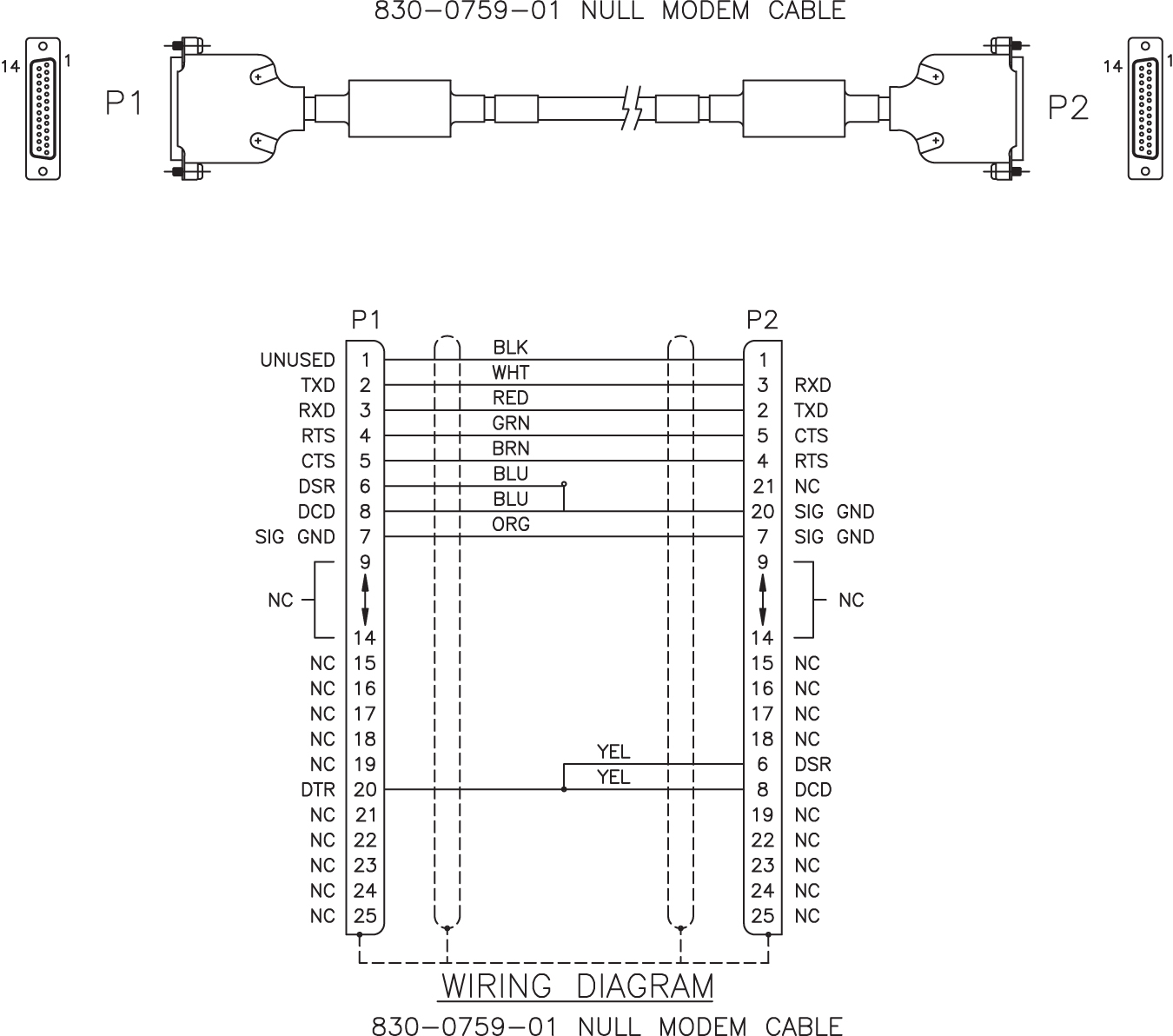
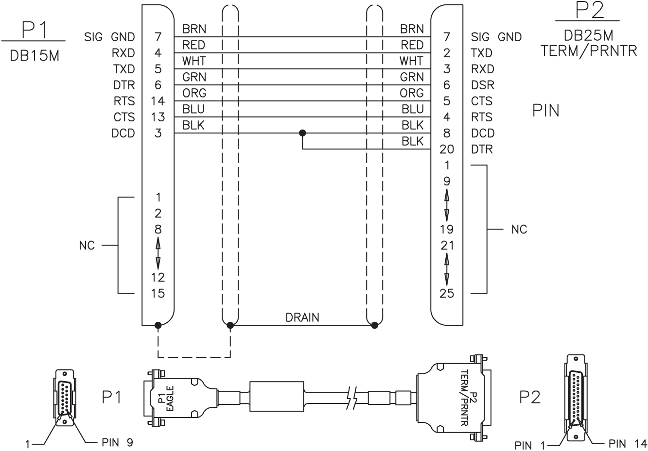
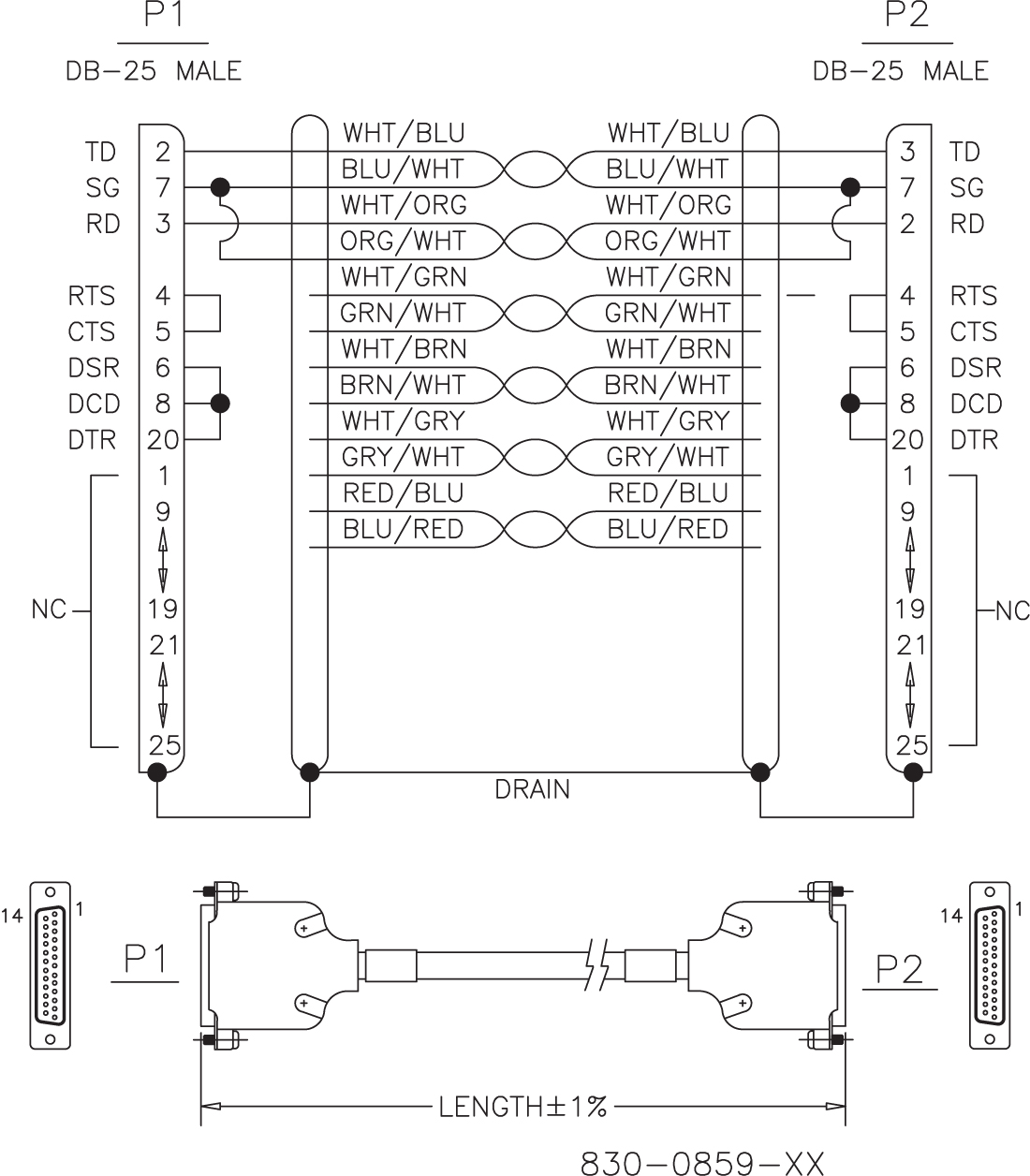
Null-Modem for Terminal Cable
Table C-20 Null-MODEM for Terminal
| Part Number | Length | Rev Level | |||
|---|---|---|---|---|---|
| North American | International | feet | inches | meters | |
|
830-0859-01 |
830-1186-01 |
.5 |
6 |
0.152 |
A |
|
830-0859-02 |
830-1186-02 |
10 |
120 |
3.48 |
A |
|
830-0859-03 |
830-1186-03 |
15 |
180 |
4.57 |
A |
|
830-0859-04 |
830-1186-04 |
20 |
240 |
6.96 |
A |
|
830-0859-05 |
830-1186-05 |
25 |
300 |
7.62 |
A |
|
830-0859-06 |
830-1186-06 |
30 |
360 |
9.14 |
A |
|
830-0859-07 |
830-1186-07 |
35 |
420 |
10.66 |
A |
|
830-0859-08 |
830-1186-08 |
50 |
600 |
15.24 |
A |
|
830-0859-09 |
830-1186-09 |
75 |
900 |
22.86 |
A |
|
830-0859-10 |
830-1186-10 |
100 |
1200 |
30.48 |
A |
|
830-0859-11 |
830-1186-11 |
125 |
1500 |
38.10 |
A |
|
830-0859-12 |
830-1186-12 |
150 |
1800 |
45.72 |
A |
|
830-0859-13 |
830-1186-13 |
200 |
2400 |
60.96 |
A |
|
830-0859-14 |
830-1186-14 |
6.0 |
72 |
1.82 |
A |
|
830-0859-15 |
830-1186-15 |
7.0 |
84 |
2.13 |
A |
Figure C-38 Null-MODEM for Terminal
Power Cable
Table C-21 Power Cable
| Part Number | Length | ||
|---|---|---|---|
| North American | International | feet | meters |
|
830-0315-01 |
-- |
4.0 |
1.07 |
|
830-0315-02 |
-- |
6.0 |
1.07 |
|
830-0315-03 |
-- |
8.0 |
2.29 |
|
830-0315-04 |
830-1147-04 |
4.5 |
1.22 |
|
830-0315-05 |
830-1147-05 |
6.5 |
1.98 |
|
830-0315-06 |
830-1147-06 |
8.5 |
2.58 |
Figure C-39 Power Cable
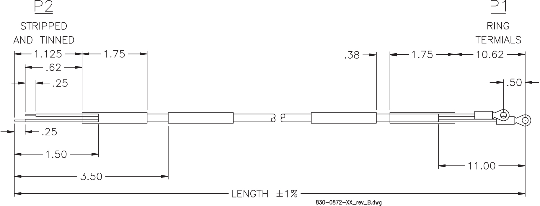
RAID Power Cable
Table C-22 RAID Power Cable
| Part Number | Length | P1 Long Lead | P2 Long Lead | Label “A” usage | Label “B” usage | |
|---|---|---|---|---|---|---|
| inches | meters | |||||
|
830-0872-01 |
91.0 |
27.73 |
Black |
Red |
BP-1, POS 3A |
RAID A, PS A |
|
830-0872-02 |
89.5 |
27.27 |
Black |
Black |
BP-2, POS 3B |
RAID A, PS B |
|
830-0872-03 |
95.0 |
28.95 |
Black |
Red |
BP-2, POS 3A |
RAID B, PS A |
|
830-0872-04 |
93.5 |
28.49 |
Black |
Black |
BP-1, POS 3B |
RAID B, PS B |
|
830-0872-05 |
95.0 |
28.95 |
Black |
Red |
Input Power |
PS A |
|
830-0872-06 |
93.5 |
28.49 |
Black |
Black |
Input Power |
PS B |
|
830-0872-07 |
49.0 |
14.93 |
Black |
Red |
BP-1, POS 5A |
RAID A, PS A |
|
830-0872-08 |
47.5 |
14.47 |
Black |
Black |
BP-2, POS 5B |
RAID A, PS B |
|
830-0872-09 |
79.5 |
24.23 |
Black |
Red |
BP-2, POS 5A |
RAID B, PS A |
|
830-0872-10 |
78.0 |
23.77 |
Black |
Black |
BP-1, POS 5B |
RAID B, PS B |
Figure C-41 RAID Power Cable
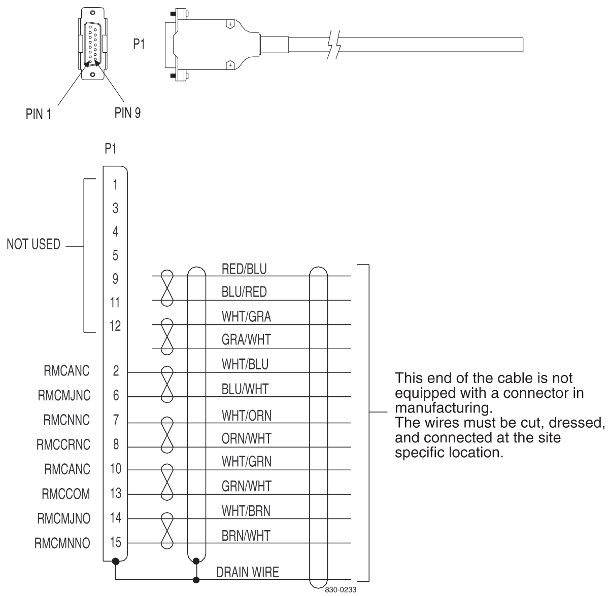
Remote Maintenance Center Cable
Table C-23 Remote Maintenance Center Cable
| Part Number | Length | ||
|---|---|---|---|
| North American | International | feet | meters |
|
830-0233-01 |
830-1146-01 |
50 |
15.25 |
|
830-0233-02 |
830-1146-02 |
75 |
22.88 |
|
830-0233-03 |
830-1146-03 |
100 |
30.50 |
|
830-0233-04 |
830-1146-04 |
125 |
38.13 |
|
830-0233-05 |
830-1146-05 |
150 |
45.75 |
|
830-0233-06 |
830-1146-06 |
175 |
53.38 |
|
830-0233-07 |
830-1146-07 |
200 |
61.00 |
|
830-0233-08 |
830-1146-08 |
250 |
76.25 |
|
830-0233-09 |
830-1146-09 |
300 |
91.50 |
|
830-0233-10 |
830-1146-10 |
500 |
152.50 |
|
830-0233-11 |
830-1146-11 |
1000 |
305.00 |
Figure C-42 Remote Maintenance Center Cable
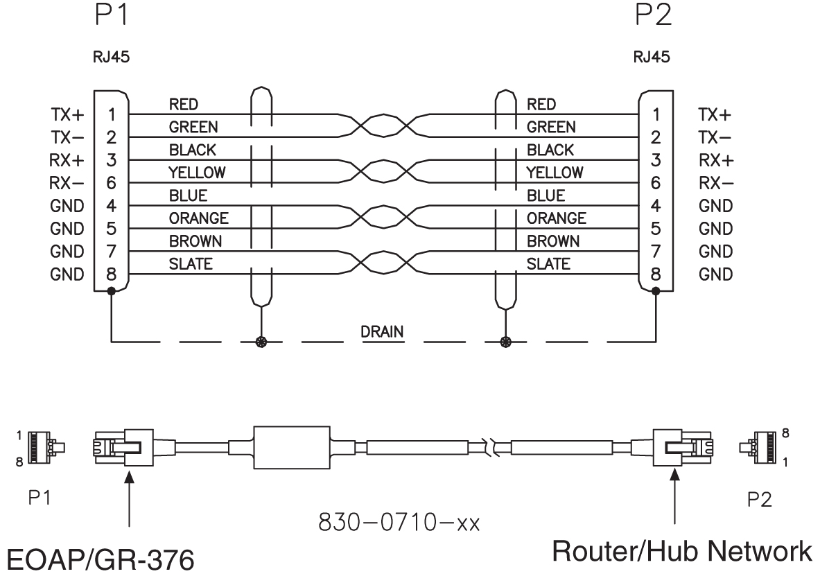
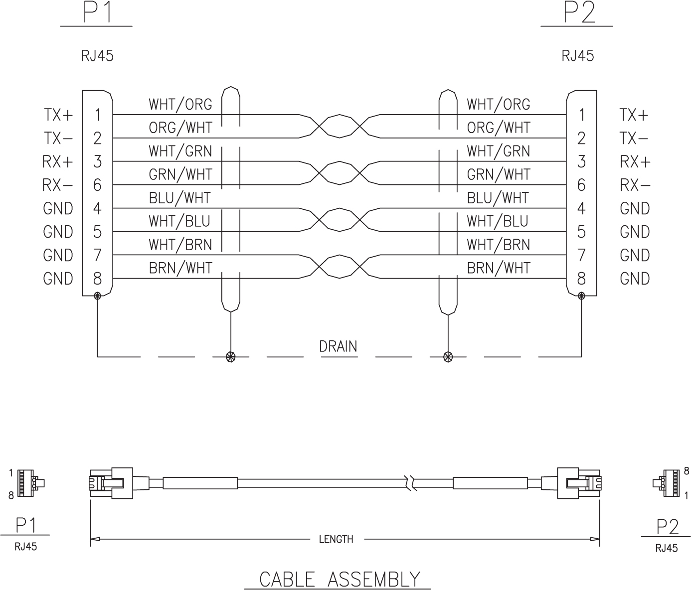
RJ45/RJ45 Cable (CAT-5) (Yellow)
Table C-24 RJ45/RJ45 Cable (CAT-5)
| Part Number | Length | ||
|---|---|---|---|
| North American | International | feet | meters |
|
830-0888-01 |
-- |
1.0 |
.304 |
|
830-0888-02 |
-- |
5.5 |
1.67 |
|
830-0888-03 |
830-1191-03 |
6.0 |
1.82 |
|
830-0888-04 |
830-1191-04 |
6.5 |
1.98 |
|
830-0888-05 |
830-1191-05 |
7.0 |
2.13 |
|
830-0888-06 |
830-1191-06 |
8.0 |
2.43 |
|
830-0888-07 |
830-1191-07 |
10.0 |
3.04 |
|
830-0888-08 |
-- |
12.0 |
3.65 |
|
830-0888-09 |
-- |
15.0 |
4.57 |
|
830-0888-10 |
-- |
16.0 |
4.87 |
|
830-0888-11 |
830-1191-11 |
3.0 |
.91 |
Figure C-43 RJ45/RJ45 Cable (CAT-5)
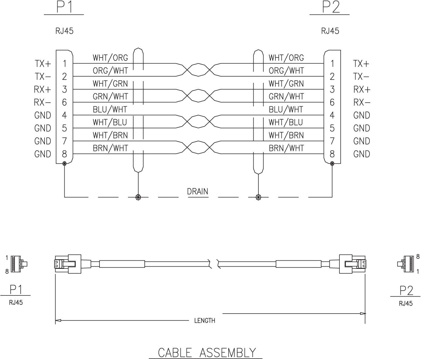
RJ45/RJ45 Cable (CAT-5) (Blue)
Table C-25 RJ45/RJ45 Cable (CAT-5)
| Part Number | Length | ||
|---|---|---|---|
| North American | International | feet | meters |
|
830-0889-01 |
-- |
1.0 |
.304 |
|
830-0889-02 |
830-1192-02 |
5.5 |
1.67 |
|
830-0889-03 |
830-1192-03 |
6.0 |
1.82 |
|
830-0889-04 |
830-1192-04 |
6.5 |
1.98 |
|
830-0889-05 |
830-1192-05 |
7.0 |
2.13 |
|
830-0889-06 |
830-1192-06 |
8.0 |
2.43 |
|
830-0889-07 |
830-1192-07 |
10.0 |
3.04 |
|
830-0889-08 |
-- |
12.0 |
3.65 |
|
830-0889-09 |
-- |
15.0 |
4.57 |
|
830-0889-10 |
-- |
16.0 |
4.87 |
Figure C-44 RJ45/RJ45 Cable (CAT-5)
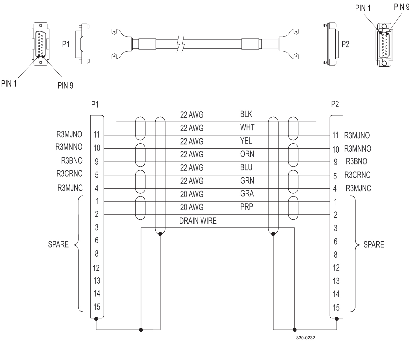
Row Alarm Cable
Table C-26 Row Alarm Cable
| Part Number | Length | ||
|---|---|---|---|
| North American | International | feet | meters |
|
830-0232-01 |
830-1145-01 |
5 |
1.53 |
|
830-0232-02 |
830-1145-02 |
8 |
2.44 |
|
830-0232-03 |
830-1145-03 |
10 |
3.05 |
|
830-0232-04 |
830-1145-04 |
12 |
3.66 |
|
830-0232-05 |
830-1145-05 |
14 |
4.27 |
|
830-0232-06 |
830-1145-06 |
175 |
53.38 |
|
830-0232-12 |
830-1145-12 |
20 |
6.1 |
|
830-0232-13 |
830-1145-13 |
30 |
9.25 |
|
830-0232-14 |
830-1145-14 |
40 |
12.2 |
|
830-0232-15 |
830-1145-15 |
50 |
15.25 |
Figure C-46 Row Alarm Cable
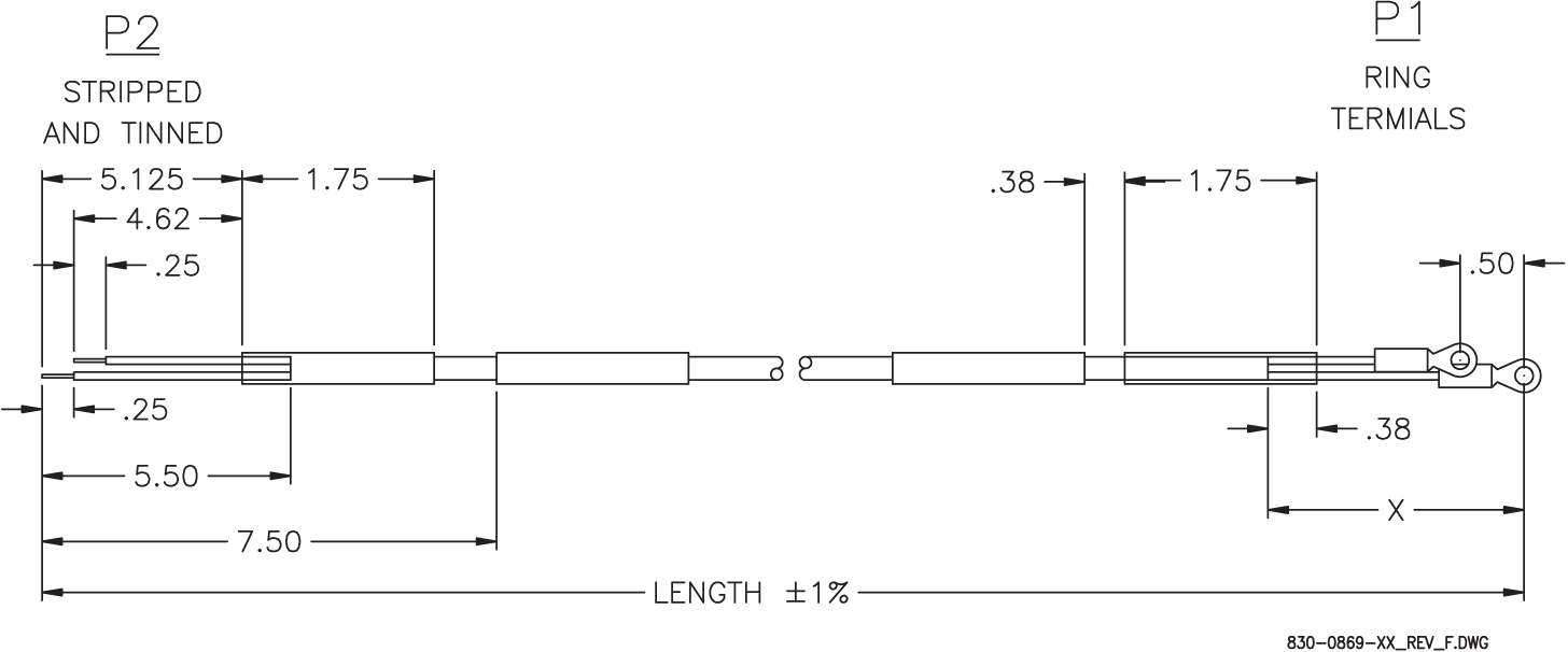
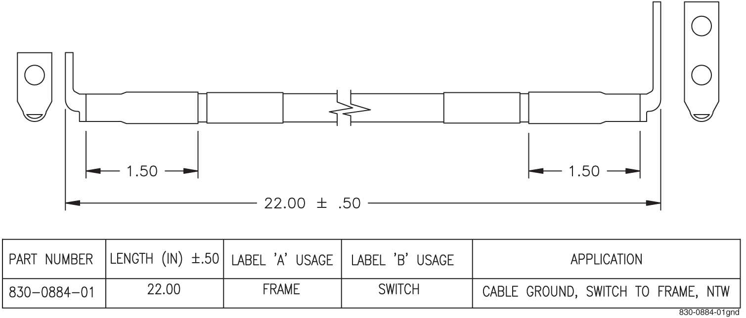
Router Power Cable
Table C-27 Router Power Cable
| Part Number | Rev Level | Length (inches) | X (inches) | P1 Long Lead | P2 Long Lead | Label “A” usage | Label “B” usage | |
|---|---|---|---|---|---|---|---|---|
| North American | International | |||||||
|
830-0869-01 |
-- |
C |
72 |
11 |
Black |
Red |
BP-1, POS 3A |
ISO Router A |
|
830-0869-02 |
-- |
C |
79 |
17 |
Black |
Red |
BP-1, POS 3B |
Dial-in Router |
|
830-0869-03 |
830-1188-03 |
C |
78 |
17 |
Black |
Red |
BP-2, POS 3B |
ISO Router B |
|
830-0869-04 |
830-1188-04 |
C |
78 |
17 |
Black |
Red |
BP-1, POS 6B |
Dial-in Router |
|
830-0869-05 |
-- |
C |
72 |
11 |
Black |
Red |
BP-1, POS 5A |
ISO Router A |
|
830-0869-06 |
-- |
C |
78 |
17 |
Black |
Red |
BP-1, POS 5B |
ISO Router B |
|
830-0869-07 |
830-1188-07 |
A |
82 |
22 |
Black |
Red |
To BP-1, POS 6B from Router YEL |
To Router YEL from BP-1 POS 6A |
|
830-0869-08 |
830-1188-08 |
A |
74 |
14 |
Black |
Red |
To BP-1, POS 6B from Router BLU |
To Router BLU from BP-1 POS 6A |
|
830-0869-09 |
-- |
A |
38 |
11 |
Black |
Red |
BP-2, POS 4A |
Dial-in Router |
Figure C-47 Router Power Cable
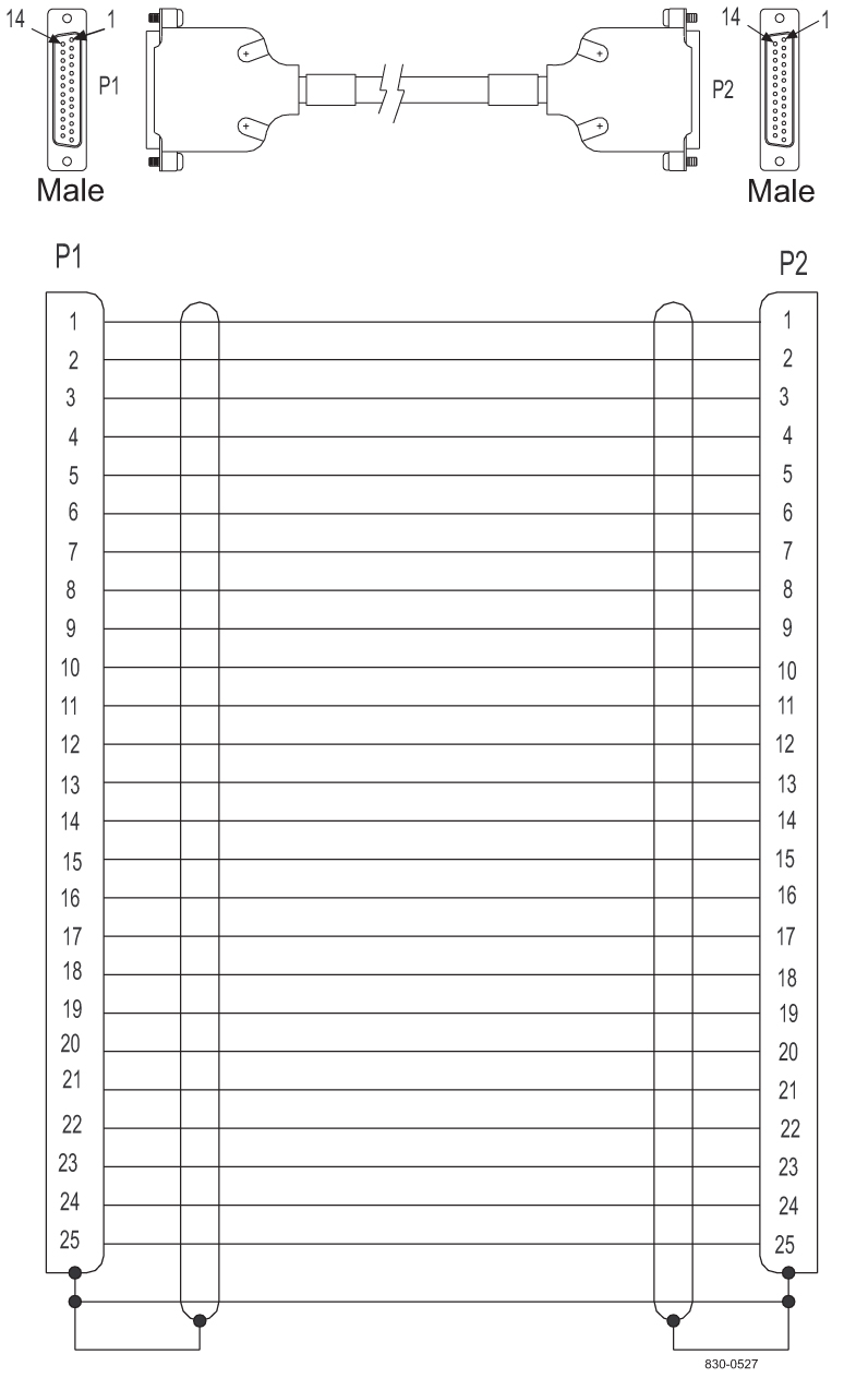
RS232
Standard Purchased part. Serial port connected to an optional second asynchronous maintenance modem and connections between the TTYA and a VT-520 terminal.
Table C-28 RS232
| Part Number | Length | ||
|---|---|---|---|
| North American | International | feet | meters |
|
830-0527-01 |
830-1152-01 |
15 |
4.57 |
|
830-0527-02 |
830-1152-02 |
25 |
7.62 |
|
830-0527-03 |
830-1152-03 |
50 |
15.24 |
|
830-0527-04 |
830-1152-04 |
75 |
22.86 |
|
830-0527-05 |
830-1152-05 |
100 |
30.48 |
|
830-0527-06 |
830-1152-06 |
125 |
38.10 |
|
830-0527-07 |
830-1152-07 |
150 |
45.72 |
Figure C-48 RS232
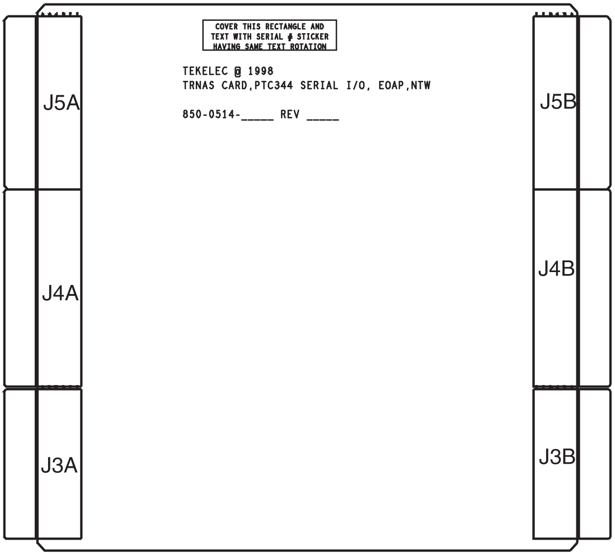
Serial I/O Transition Card
Table C-29 Serial I/O Transition Card
| Part Number | Length | ||
|---|---|---|---|
| North American | International | feet | meters |
|
830-0514-01 |
--- |
5 |
1.53 |
|
830-0514-02 |
--- |
10 |
3.05 |
|
830-0514-03 |
--- |
15 |
4.57 |
|
830-0514-04 |
--- |
20 |
6.1 |
|
830-0514-05 |
--- |
25 |
7.62 |
Figure C-49 Serial I/O Transition Card
Shielded Straight Through Cable (CAT-5)
Table C-30 Shielded Straight Through CAT-5 Cable
| Part Number | Length | ||
|---|---|---|---|
| North American | International | meters | feet |
|
830-0724-10 |
830-1174-10 |
30.48 |
100.0 |
|
830-0724-43 |
830-1174-43 |
60.96 |
200.0 |
|
830-0724-63 |
830-1174-63 |
91.44 |
300.0 |
Figure C-52 Straight Through Cable (CAT-5)
Terminal/Converter Cable
This converter is a purchased part and the pin-out is that of a straight through converter. The cable is 2 ft long. There is no illustration or wiring diagram.
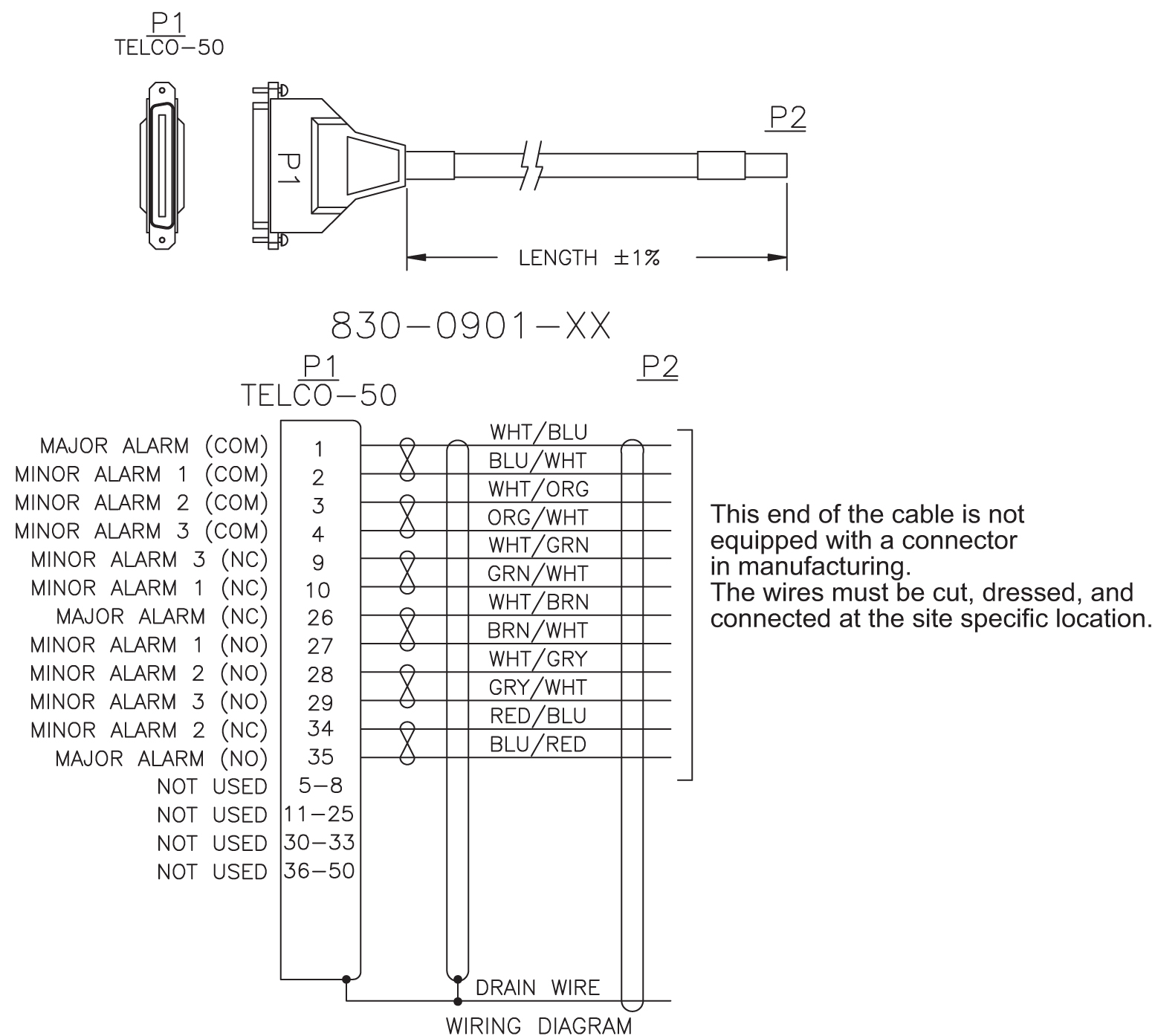
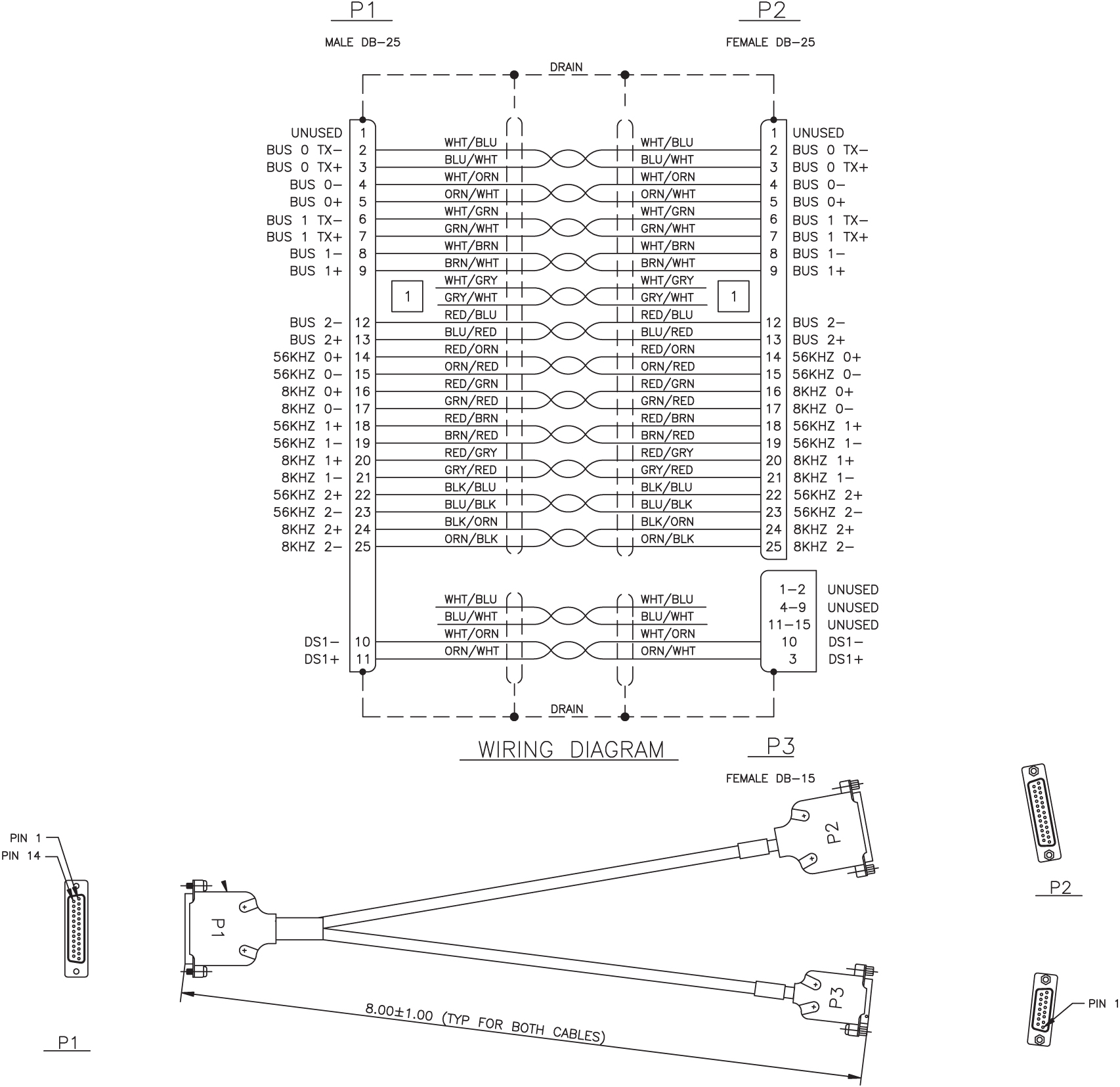
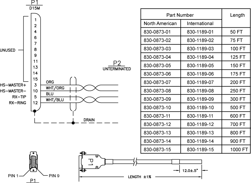
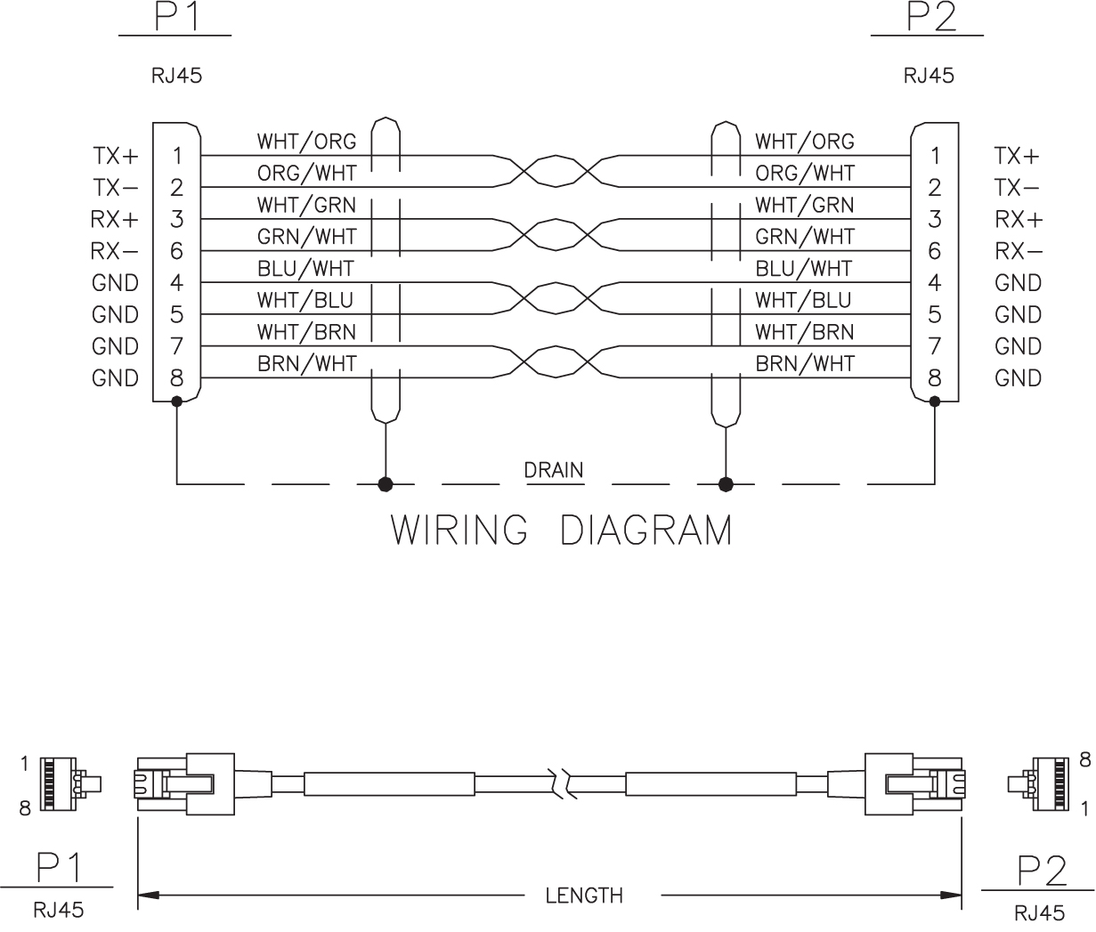
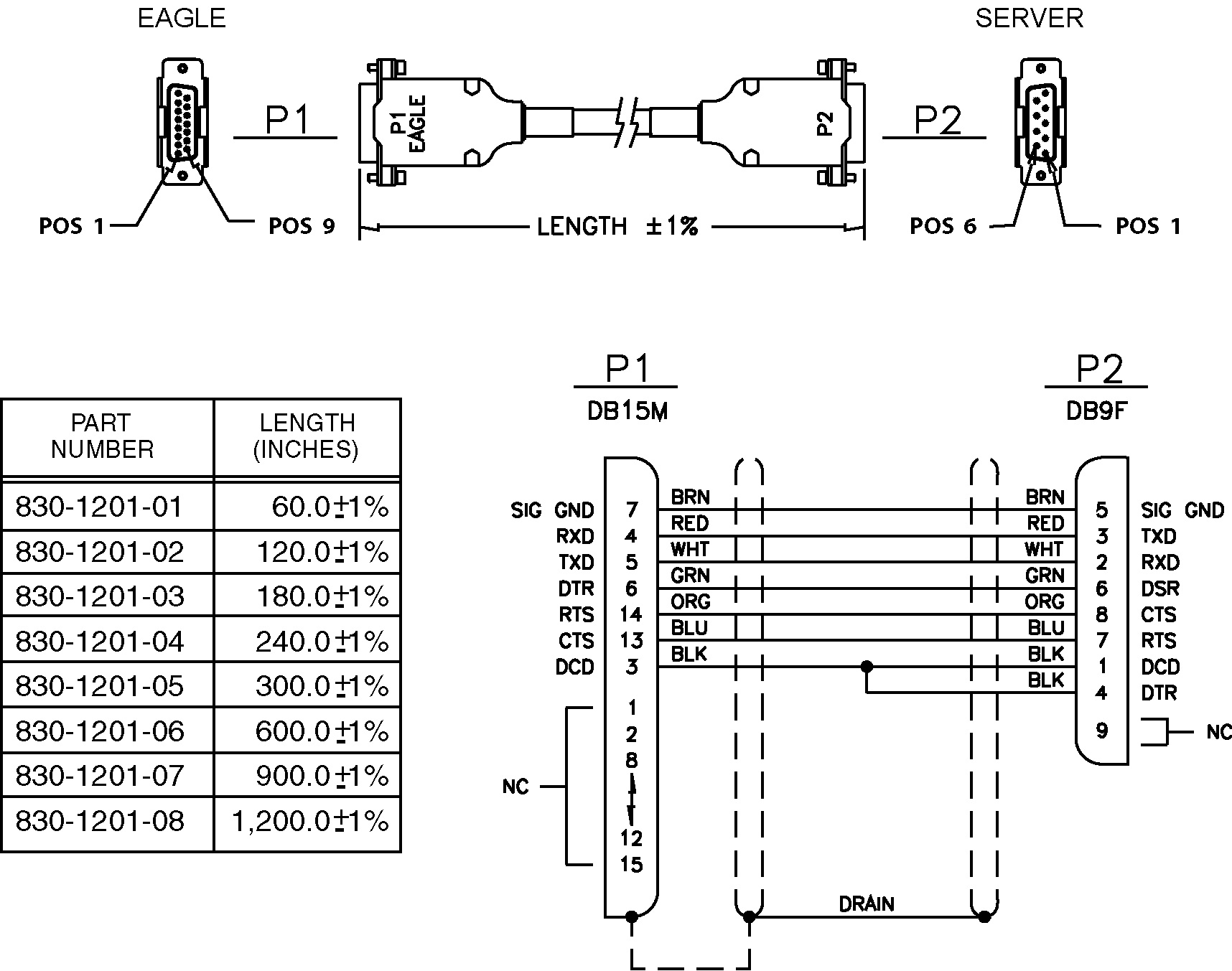
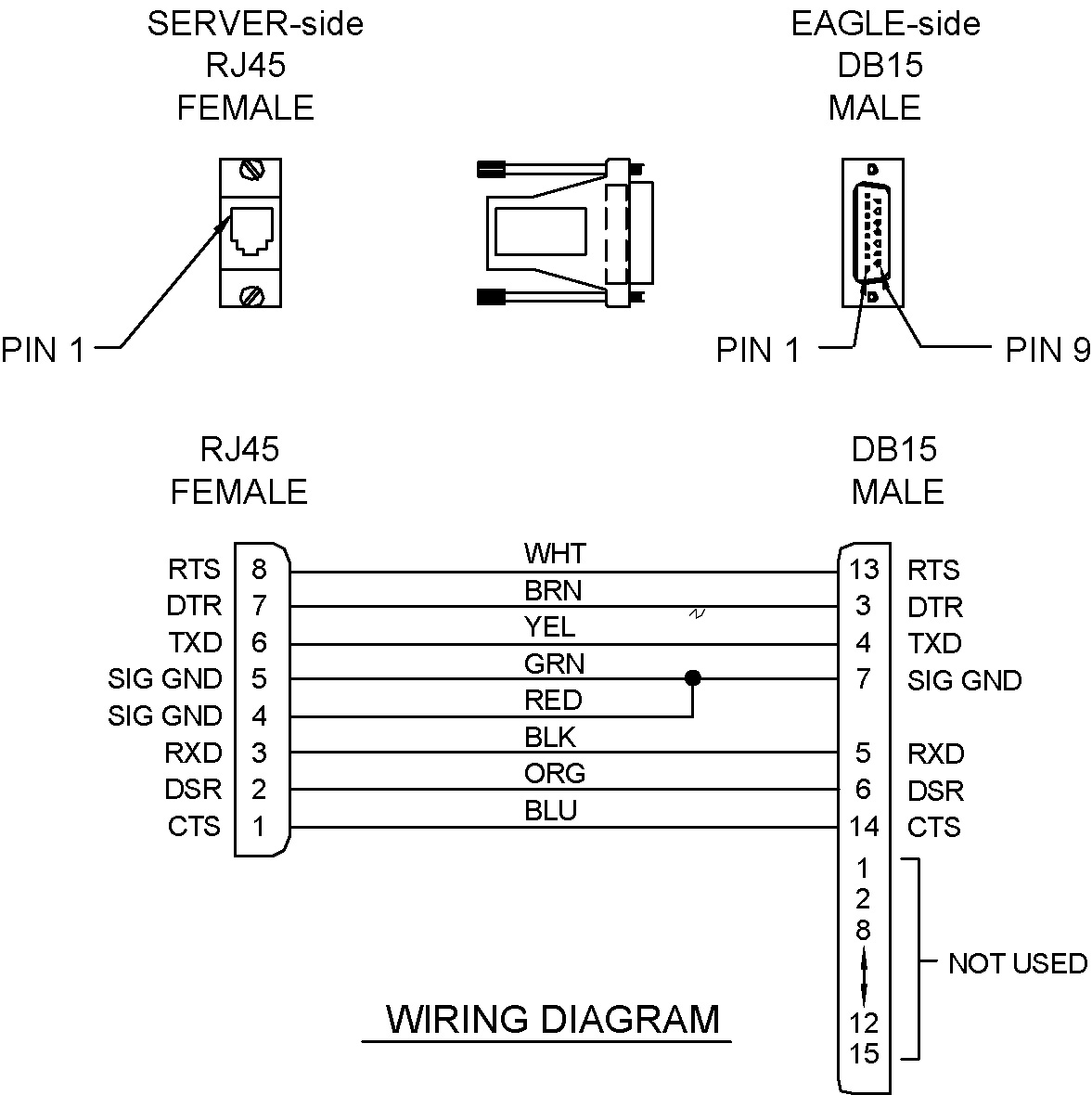
Terminal/Server Serial Cable with Flow Control
Figure C-56 Terminal Server Serial Cable with Flow Control (P/N 830-1201-xx)
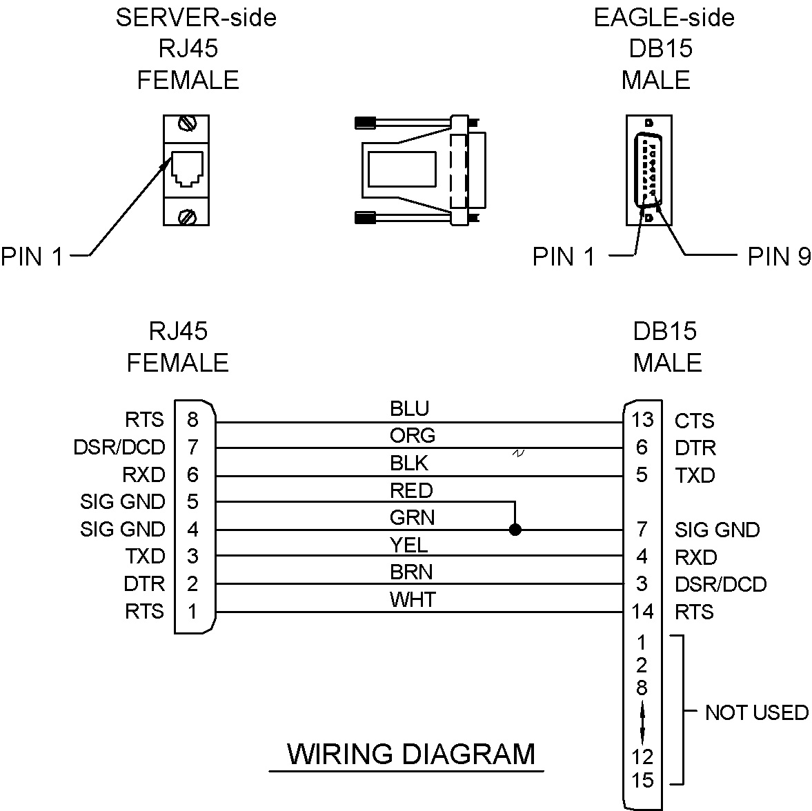
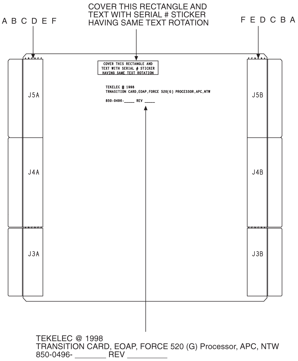
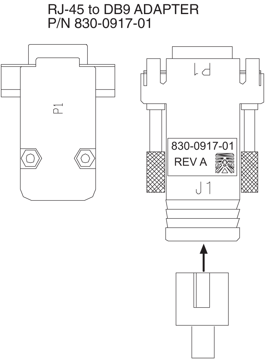
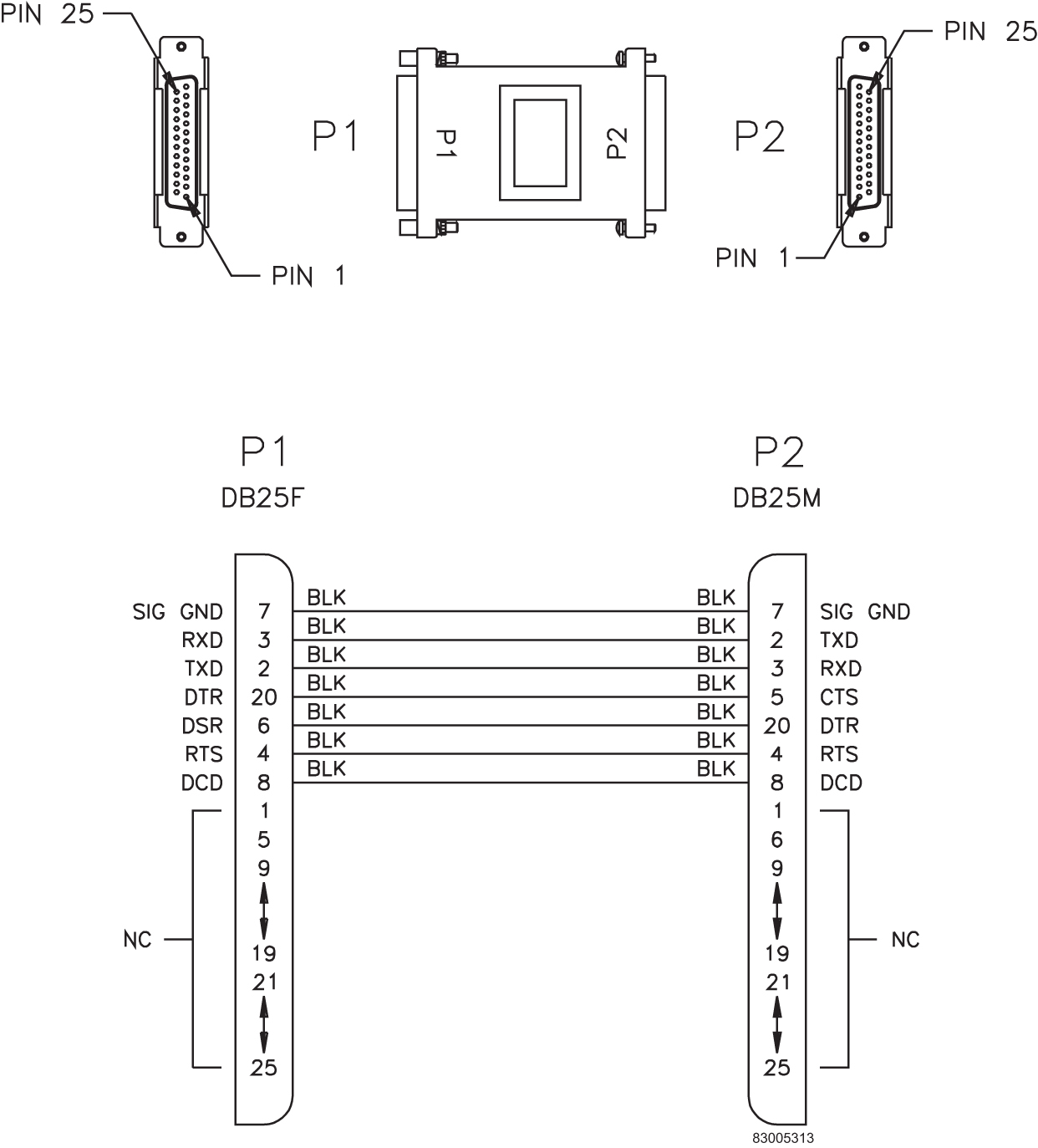
Terminal/Server Serial Port Adapter, NTW
Figure C-57 Terminal/Server Serial Port Adapter, NTW (P/N 830-0915-01)
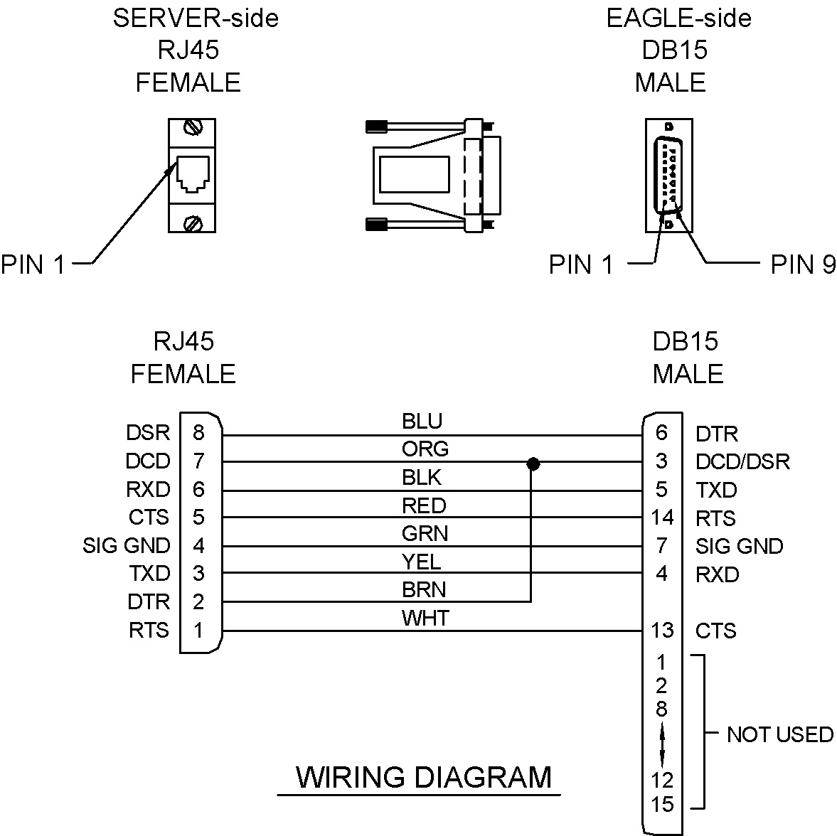
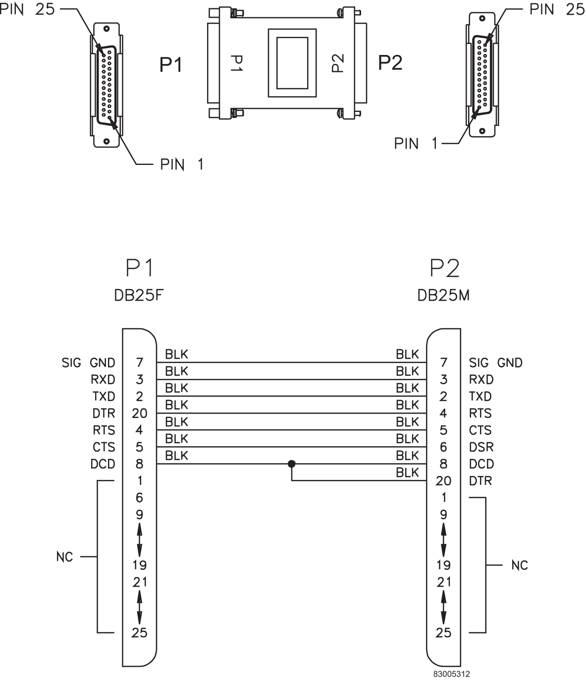
Terminal/Server Serial Port Adapter, MRV
Figure C-58 Terminal/Server Serial Port Adapter, MRV (P/N 830-0915-02)